AUDI A4 2000 B5 / 1.G ATQ Engine Additional Signals Testing Owner's Guide
Manufacturer: AUDI, Model Year: 2000, Model line: A4, Model: AUDI A4 2000 B5 / 1.GPages: 44, PDF Size: 0.19 MB
Page 31 of 44
24-188
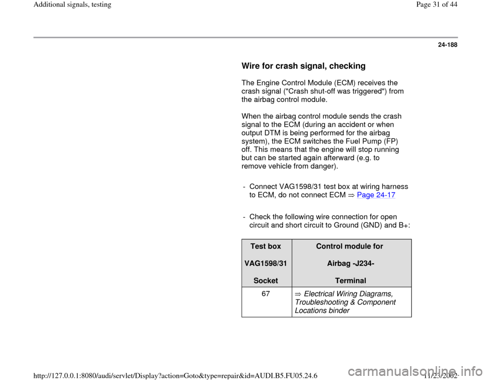
Wire for crash signal, checking
The Engine Control Module (ECM) receives the
crash signal ("Crash shut-off was triggered") from
the airbag control module.
When the airbag control module sends the crash
signal to the ECM (during an accident or when
output DTM is being performed for the airbag
system), the ECM switches the Fuel Pump (FP)
off. This means that the engine will stop running
but can be started again afterward (e.g. to
remove vehicle from danger).
- Connect VAG1598/31 test box at wiring harness
to ECM, do not connect ECM Page 24
-17
- Check the following wire connection for open
circuit and short circuit to Ground (GND) and B+:
Test box
VAG1598/31
Socket
Control module for
Airbag -J234-
Terminal
67 Electrical Wiring Diagrams,
Troubleshooting & Component
Locations binder
Pa
ge 31 of 44 Additional si
gnals, testin
g
11/23/2002 htt
p://127.0.0.1:8080/audi/servlet/Dis
play?action=Goto&t
yp
e=re
pair&id=AUDI.B5.FU05.24.6
Page 32 of 44
24-189
- Repair open circuit or short circuit if
necessary.
Electrical Wiring Diagrams, Troubleshooting &
Component Locations binder If no malfunctions are found in wire:
- Check DTC memory of control module for
airbag:
Repair Manual, Body
-On Board Diagnostic
(OBD), Repair Group 01; On Board Diagnostic (OBD) of airbag system BAE (basic trigger unit) with side airbag; DTC memory, checking
Pa
ge 32 of 44 Additional si
gnals, testin
g
11/23/2002 htt
p://127.0.0.1:8080/audi/servlet/Dis
play?action=Goto&t
yp
e=re
pair&id=AUDI.B5.FU05.24.6
Page 33 of 44
24-190
Rough terrain signal from ABS/EDL
control module, checking
Notes:
When the ABS/EDL control module recognizes
that a wheel is spinning, the ABS/EDL control
module generates the rough terrain signal.
When the Engine Control Module (ECM)
recognizes the rough terrain signal, combustion
misfire recognition is switched off in the Engine
Control Module (ECM).
Only check the rough terrain signal if the
malfunction "18014 (P1606) rough terrain
info/engine torque from ABS cont. mod.
Electrical malfunction in circuit" is stored DTC
memory.It is possible that the malfunction
"Combustion misfire" is also stored in DTC
memory as a side effect and it can be
disregarded.
The wire connection and rough terrain signal
are monitored by the Engine Control Module
(ECM).
Pa
ge 33 of 44 Additional si
gnals, testin
g
11/23/2002 htt
p://127.0.0.1:8080/audi/servlet/Dis
play?action=Goto&t
yp
e=re
pair&id=AUDI.B5.FU05.24.6
Page 34 of 44
24-191
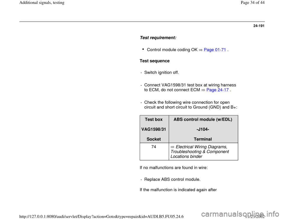
Test requirement:
Control module coding OK Page 01
-71
.
Test sequence
- Switch ignition off.
- Connect VAG1598/31 test box at wiring harness
to ECM, do not connect ECM Page 24
-17
.
- Check the following wire connection for open
circuit and short circuit to Ground (GND) and B+:
Test box
VAG1598/31
Socket
ABS control module (w/EDL)
-J104-
Terminal
74 Electrical Wiring Diagrams,
Troubleshooting & Component
Locations binder
If no malfunctions are found in wire:
- Replace ABS control module.
If the malfunction is indicated again after
Pa
ge 34 of 44 Additional si
gnals, testin
g
11/23/2002 htt
p://127.0.0.1:8080/audi/servlet/Dis
play?action=Goto&t
yp
e=re
pair&id=AUDI.B5.FU05.24.6
Page 35 of 44
replacing the ABS control module:
- Replace Engine Control Module (ECM) Page
24
-21
.
Pa
ge 35 of 44 Additional si
gnals, testin
g
11/23/2002 htt
p://127.0.0.1:8080/audi/servlet/Dis
play?action=Goto&t
yp
e=re
pair&id=AUDI.B5.FU05.24.6
Page 36 of 44
24-192
Data transfer between Engine Control
Module (ECM) and CAN capable control
modules, checking
Notes:
Data exchange between individual control
modules occurs via a bus system.
The term "CAN-bus" refers to a system that
transports and distributes data.
The wire connections between the control
modules, via which data is transferred, are
referred to as data wires.
Data is transferred to the connected control
modules serially (one after the other) via these
data wires (i.e. engine speed, accelerator
position).
Checking bus system
The DTC table suggested checking the data
exchange between the Engine Control Module
(ECM) and CAN capable control modules.
-
Connect VAS5051 tester or VAG1551 scan tool
and select the control module for engine
electronics using "address word" 01 Page 01
-
Pa
ge 36 of 44 Additional si
gnals, testin
g
11/23/2002 htt
p://127.0.0.1:8080/audi/servlet/Dis
play?action=Goto&t
yp
e=re
pair&id=AUDI.B5.FU05.24.6
Page 37 of 44
9 .
Ignition must remain switched on for this.
Pa
ge 37 of 44 Additional si
gnals, testin
g
11/23/2002 htt
p://127.0.0.1:8080/audi/servlet/Dis
play?action=Goto&t
yp
e=re
pair&id=AUDI.B5.FU05.24.6
Page 38 of 44
24-193
Rapid data transfer
HELP
Select function XX
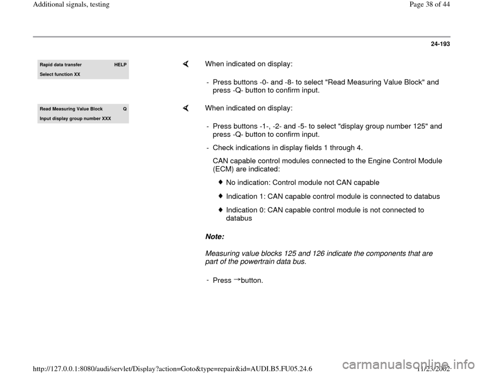
When indicated on display:
- Press buttons -0- and -8- to select "Read Measuring Value Block" and
press -Q- button to confirm input.
Read Measuring Value Block
Q
Input displa
y group number XXX
When indicated on display:
Note:
Measuring value blocks 125 and 126 indicate the components that are
part of the powertrain data bus. - Press buttons -1-, -2- and -5- to select "display group number 125" and
press -Q- button to confirm input.
- Check indications in display fields 1 through 4.
CAN capable control modules connected to the Engine Control Module
(ECM) are indicated:
No indication: Control module not CAN capable
Indication 1: CAN capable control module is connected to databus
Indication 0: CAN capable control module is not connected to
databus
-
Press button.
Pa
ge 38 of 44 Additional si
gnals, testin
g
11/23/2002 htt
p://127.0.0.1:8080/audi/servlet/Dis
play?action=Goto&t
yp
e=re
pair&id=AUDI.B5.FU05.24.6
Page 39 of 44
24-194
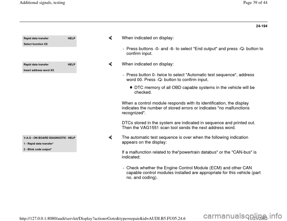
Rapid data transfer
HELP
Select function XX
When indicated on display:
- Press buttons -0- and -6- to select "End output" and press -Q- button to
confirm input.
Rapid data transfer
HELP
Insert address word XX
When indicated on display:
When a control module responds with its identification, the display
indicates the number of stored errors or indicates "no malfunctions
recognized".
DTCs stored in the system are indicated in sequence and printed out.
Then the VAG1551 scan tool sends the next address word. - Press button 0- twice to select "Automatic test sequence", address
word 00. Press -Q- button to confirm input.
DTC memory of all OBD capable systems in the vehicle will be
checked.
V.A.G - ON BOARD DIAGNOSTIC
HELP
1 - Rapid data transfer*2 - Blink code output*
The automatic test sequence is over when the following indication
appears on the display:
If a malfunction related to the"powertrain databus" or the "CAN-bus" is
indicated:
- Check whether the Engine Control Module (ECM) and other CAN
capable control modules installed are appropriate for this vehicle (part
no. and coding).
Pa
ge 39 of 44 Additional si
gnals, testin
g
11/23/2002 htt
p://127.0.0.1:8080/audi/servlet/Dis
play?action=Goto&t
yp
e=re
pair&id=AUDI.B5.FU05.24.6
Page 40 of 44
24-195
If the correct control modules are installed:
- Check to be sure the multi-pin connectors of the
control modules are securely connected.
If multi-pin connectors are properly secured:
- Check CAN bus system
Checking a "two-line bus system"
Three or more control modules are
communicating across a "two-line bus
system".
- Analyze the DTCs stored in the memories of the
control modules.
Note:
This analysis will help you locate the cause of the
line malfunction.
Pa
ge 40 of 44 Additional si
gnals, testin
g
11/23/2002 htt
p://127.0.0.1:8080/audi/servlet/Dis
play?action=Goto&t
yp
e=re
pair&id=AUDI.B5.FU05.24.6