coolant AUDI A4 2000 B5 / 1.G ATQ Engine Ignition System Checking Workshop Manual
[x] Cancel search | Manufacturer: AUDI, Model Year: 2000, Model line: A4, Model: AUDI A4 2000 B5 / 1.GPages: 65, PDF Size: 0.53 MB
Page 19 of 65
28-16
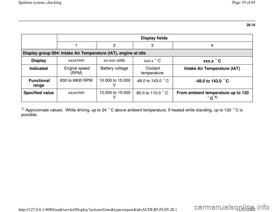
Display fields
1 2 3 4
Display group 004: Intake Air Temperature (IAT), engine at idle
Display xxxx/min xx.xxx volts
xxx.x C
xxx.x C
Indicated Engine speed
(RPM) Battery voltage Coolant
temperature Intake Air Temperature (IAT)
Functional
range 630 to 6800 RPM 10.000 to 15.000
V -48.0 to 143.0 C
-48.0 to 143.0 C
Specified value xxxx/min 12.000 to 15.000
V 80.0 to 110.0 C
From ambient temperature up to 120
C
1)
1) Approximate values: While driving, up to 24 C above ambient temperature. If heated while standing, up to 120 C is
possible.
Pa
ge 19 of 65 I
gnition s
ystem, checkin
g
11/23/2002 htt
p://127.0.0.1:8080/audi/servlet/Dis
play?action=Goto&t
yp
e=re
pair&id=AUDI.B5.FU05.28.1
Page 26 of 65
28-23
Engine Coolant Temperature (ECT) sensor
-G62-, checking
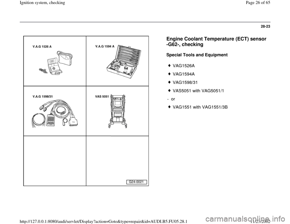
Special Tools and Equipment
VAG1526A
VAG1594A
VAG1598/31
VAS5051 with VAG5051/1
- or
VAG1551 with VAG1551/3B
Pa
ge 26 of 65 I
gnition s
ystem, checkin
g
11/23/2002 htt
p://127.0.0.1:8080/audi/servlet/Dis
play?action=Goto&t
yp
e=re
pair&id=AUDI.B5.FU05.28.1
Page 28 of 65
28-25
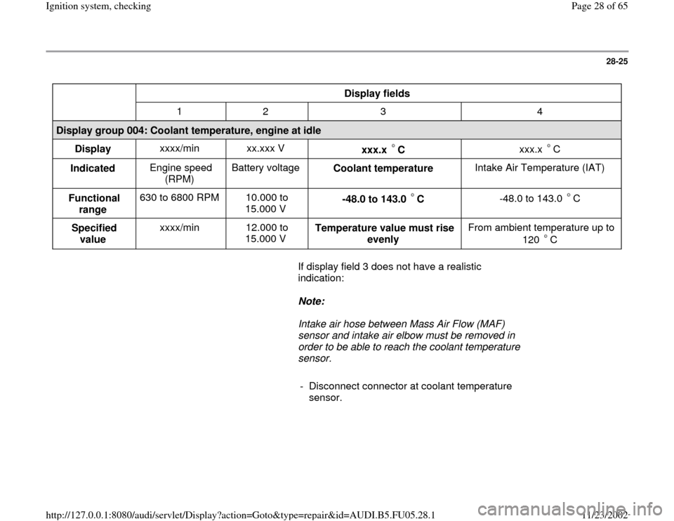
Display fields
1 2 3 4
Display group 004: Coolant temperature, engine at idle
Display xxxx/min xx.xxx V
xxx.x C
xxx.x C
Indicated Engine speed
(RPM) Battery voltage
Coolant temperature Intake Air Temperature (IAT)
Functional
range 630 to 6800 RPM 10.000 to
15.000 V -48.0 to 143.0 C
-48.0 to 143.0 C
Specified
value xxxx/min 12.000 to
15.000 V Temperature value must rise
evenly From ambient temperature up to
120 C
If display field 3 does not have a realistic
indication:
Note:
Intake air hose between Mass Air Flow (MAF)
sensor and intake air elbow must be removed in
order to be able to reach the coolant temperature
sensor.
- Disconnect connector at coolant temperature
sensor.
Pa
ge 28 of 65 I
gnition s
ystem, checkin
g
11/23/2002 htt
p://127.0.0.1:8080/audi/servlet/Dis
play?action=Goto&t
yp
e=re
pair&id=AUDI.B5.FU05.28.1
Page 29 of 65
28-26
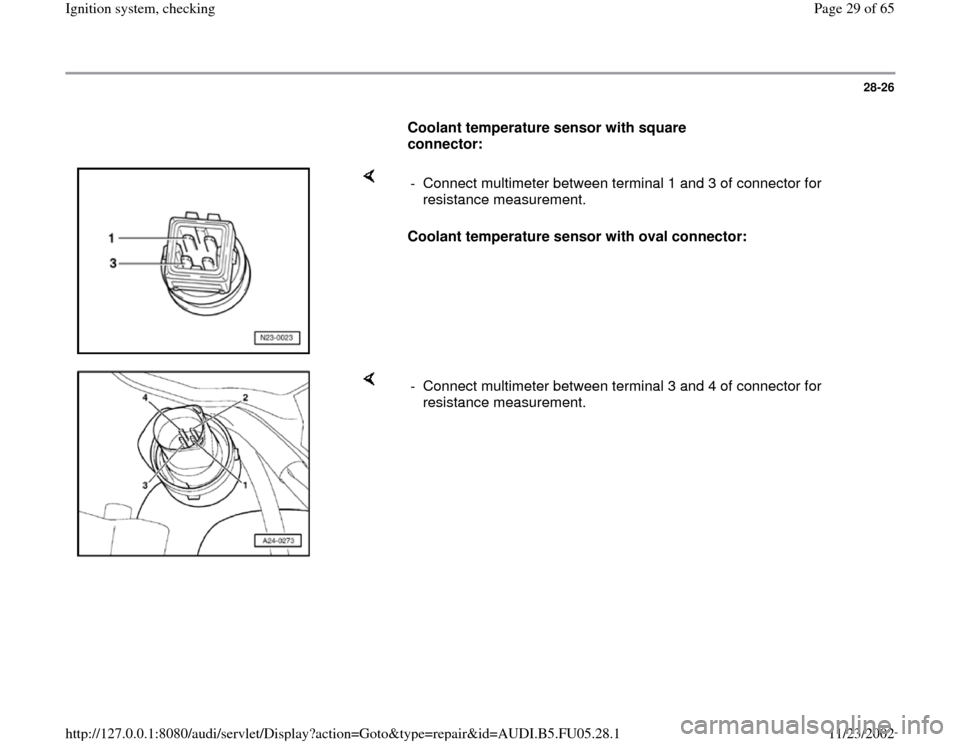
Coolant temperature sensor with square
connector:
Coolant temperature sensor with oval connector: - Connect multimeter between terminal 1 and 3 of connector for
resistance measurement.
- Connect multimeter between terminal 3 and 4 of connector for
resistance measurement.
Pa
ge 29 of 65 I
gnition s
ystem, checkin
g
11/23/2002 htt
p://127.0.0.1:8080/audi/servlet/Dis
play?action=Goto&t
yp
e=re
pair&id=AUDI.B5.FU05.28.1
Page 30 of 65
28-27
All models
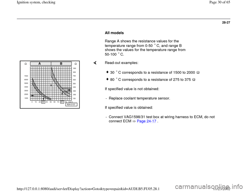
Range A shows the resistance values for the
temperature range from 0-50 C, and range B
shows the values for the temperature range from
50-100 C.
Read-out examples:
If specified value is not obtained:
If specified value is obtained:
30 C corresponds to a resistance of 1500 to 2000 80 C corresponds to a resistance of 275 to 375
- Replace coolant temperature sensor.
- Connect VAG1598/31 test box at wiring harness to ECM, do not
connect ECM Page 24
-17
.
Pa
ge 30 of 65 I
gnition s
ystem, checkin
g
11/23/2002 htt
p://127.0.0.1:8080/audi/servlet/Dis
play?action=Goto&t
yp
e=re
pair&id=AUDI.B5.FU05.28.1
Page 31 of 65
28-28
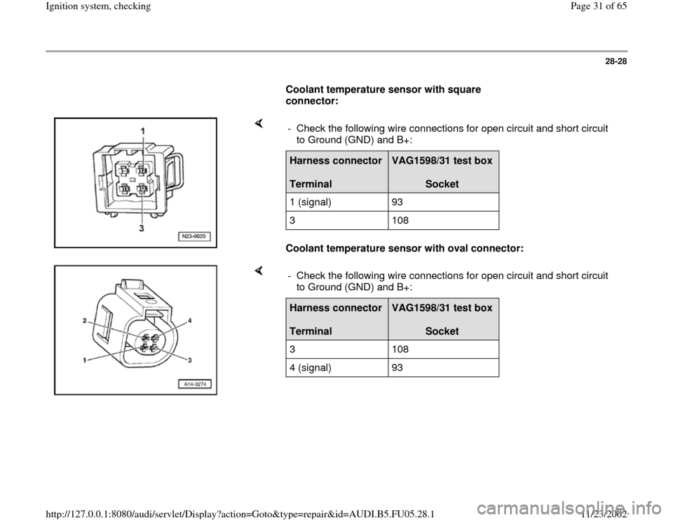
Coolant temperature sensor with square
connector:
Coolant temperature sensor with oval connector: - Check the following wire connections for open circuit and short circuit
to Ground (GND) and B+: Harness connector
Terminal
VAG1598/31 test box
Socket
1 (signal) 93
3 108
- Check the following wire connections for open circuit and short circuit
to Ground (GND) and B+: Harness connector
Terminal
VAG1598/31 test box
Socket
3 108
4 (signal) 93
Pa
ge 31 of 65 I
gnition s
ystem, checkin
g
11/23/2002 htt
p://127.0.0.1:8080/audi/servlet/Dis
play?action=Goto&t
yp
e=re
pair&id=AUDI.B5.FU05.28.1
Page 47 of 65
28-42
Component location Overview of Component
Locations, page Page 24
-5
Notes:
Knock Sensor (KS) 1 -G61- and Knock Sensor
(KS) 2 -G66- themselves cannot be electrically
tested.
Use only gold-plated terminals when servicing
harness connector for knock sensors.
For the knock sensors to function properly, it is
important that tightening torque be exactly 20
Nm.
Check harness connector from knock sensor to
wiring harness for corrosion.
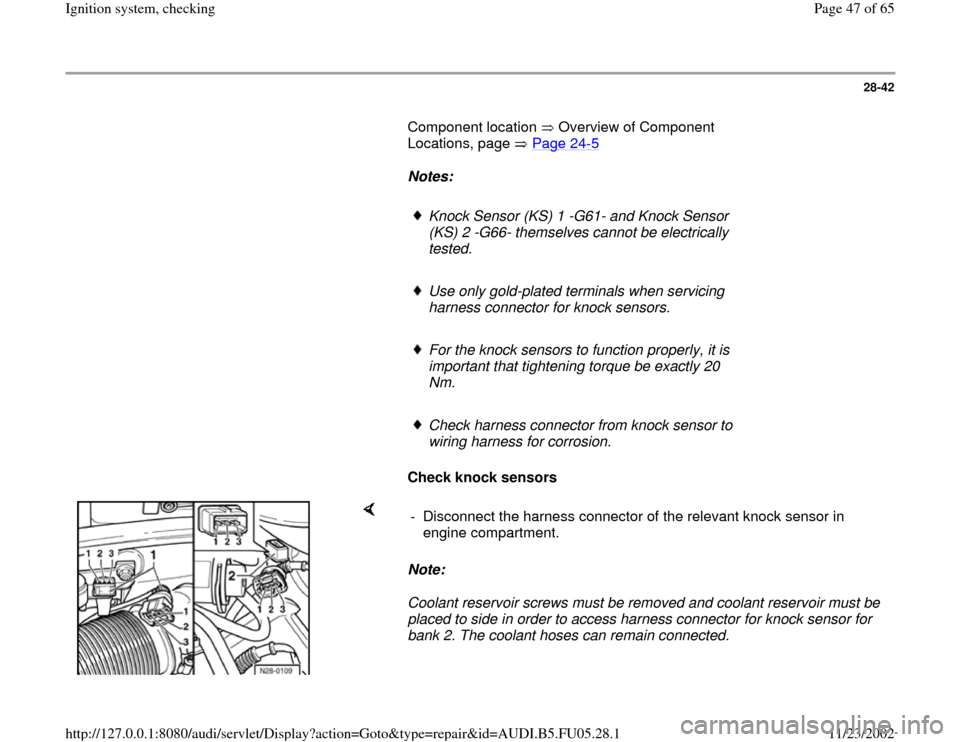
Check knock sensors
Note:
Coolant reservoir screws must be removed and coolant reservoir must be
placed to side in order to access harness connector for knock sensor for
bank 2. The coolant hoses can remain connected. - Disconnect the harness connector of the relevant knock sensor in
engine compartment.
Pa
ge 47 of 65 I
gnition s
ystem, checkin
g
11/23/2002 htt
p://127.0.0.1:8080/audi/servlet/Dis
play?action=Goto&t
yp
e=re
pair&id=AUDI.B5.FU05.28.1