AUDI A4 2000 B5 / 1.G Instrument Cluster Location Diagram Through Model Year 2000 Workshop Manual
Manufacturer: AUDI, Model Year: 2000,
Model line: A4,
Model: AUDI A4 2000 B5 / 1.G
Pages: 28, PDF Size: 0.15 MB
AUDI A4 2000 B5 / 1.G Instrument Cluster Location Diagram Through Model Year 2000 Workshop Manual
A4 2000 B5 / 1.G
AUDI
AUDI
https://www.carmanualsonline.info/img/6/915/w960_915-0.png
AUDI A4 2000 B5 / 1.G Instrument Cluster Location Diagram Through Model Year 2000 Workshop Manual
Trending: wheel, tailgate, engine, tow, high beam, engine coolant, reset
Page 1 of 28
90-25
Instrument cluster (from M.Y.
2000)
WARNING!
Disconnect battery Ground (GND) cable
before performing work on the electrical
system.
Notes:
Obtain radio code before disconnecting
battery.
Be sure to activate vehicle features (radio,
clock, electric window regulator, engine)
according to owner's manual when the battery
is re-connected.
Pa
ge 1 of 28 Instrument cluster
(from M.Y. 2000
)
11/20/2002 htt
p://127.0.0.1:8080/audi/servlet/Dis
play?action=Goto&t
yp
e=re
pair&id=AUDI.B5.EE01.90.2
Page 2 of 28
90-26
Malfunction message "dEF" on trip
odometer display
If the control module in the instrument cluster
detects a malfunction in its permanent memory,
the letters "dEF" will appear on the trip odometer
display.
- If "dEF" is indicated on display, replace
instrument cluster Page 90
-27
.
Pa
ge 2 of 28 Instrument cluster
(from M.Y. 2000
)
11/20/2002 htt
p://127.0.0.1:8080/audi/servlet/Dis
play?action=Goto&t
yp
e=re
pair&id=AUDI.B5.EE01.90.2
Page 3 of 28
90-27
Instrument cluster, removing and
installing
Notes:
Do not disassemble instrument cluster.
Removing the steering wheel is not required.
For clarity, the steering wheel does not appear
in the following illustrations.
Check DTC memory before removing the
instrument cluster Page 01
-91
.
Also check and write down values of the service
display and the odometer reading via the
VAG1551 scan tool Page 01
-133
.
Pa
ge 3 of 28 Instrument cluster
(from M.Y. 2000
)
11/20/2002 htt
p://127.0.0.1:8080/audi/servlet/Dis
play?action=Goto&t
yp
e=re
pair&id=AUDI.B5.EE01.90.2
Page 4 of 28
90-28
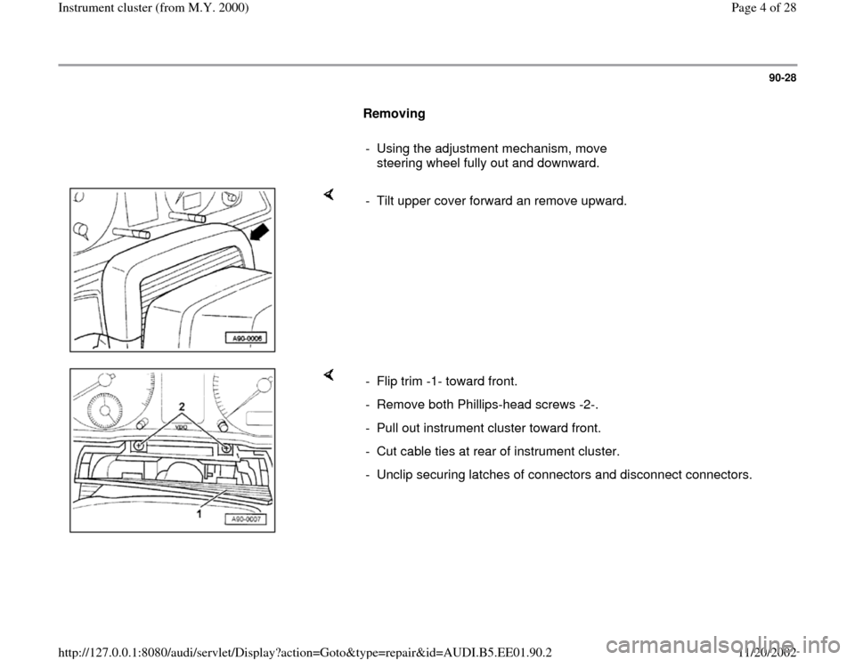
Removing
- Using the adjustment mechanism, move
steering wheel fully out and downward.
- Tilt upper cover forward an remove upward.
- Flip trim -1- toward front.
- Remove both Phillips-head screws -2-.
- Pull out instrument cluster toward front.
- Cut cable ties at rear of instrument cluster.
- Unclip securing latches of connectors and disconnect connectors.
Pa
ge 4 of 28 Instrument cluster
(from M.Y. 2000
)
11/20/2002 htt
p://127.0.0.1:8080/audi/servlet/Dis
play?action=Goto&t
yp
e=re
pair&id=AUDI.B5.EE01.90.2
Page 5 of 28
90-29
Installing
- Connect electrical harness connectors and affix
wiring harness to rear of instrument cluster with
cable ties.
- To install, perform the steps described for
removal in reverse order.
- Perform a function test after installation.
- If function test is OK
observe notes for the replacement of the
instrument cluster Page 01
-191
.
Pa
ge 5 of 28 Instrument cluster
(from M.Y. 2000
)
11/20/2002 htt
p://127.0.0.1:8080/audi/servlet/Dis
play?action=Goto&t
yp
e=re
pair&id=AUDI.B5.EE01.90.2
Page 6 of 28
90-30
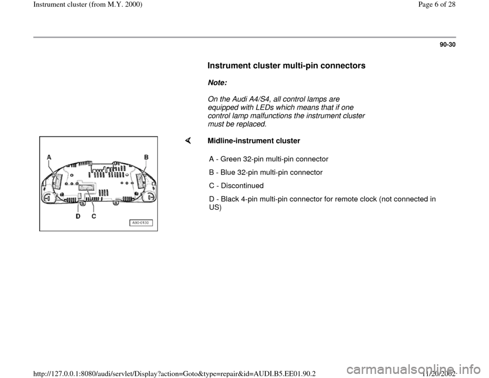
Instrument cluster multi-pin connectors
Note:
On the Audi A4/S4, all control lamps are
equipped with LEDs which means that if one
control lamp malfunctions the instrument cluster
must be replaced.
Midline-instrument cluster
A - Green 32-pin multi-pin connector
B - Blue 32-pin multi-pin connector
C - Discontinued
D - Black 4-pin multi-pin connector for remote clock (not connected in
US)
Pa
ge 6 of 28 Instrument cluster
(from M.Y. 2000
)
11/20/2002 htt
p://127.0.0.1:8080/audi/servlet/Dis
play?action=Goto&t
yp
e=re
pair&id=AUDI.B5.EE01.90.2
Page 7 of 28
90-31
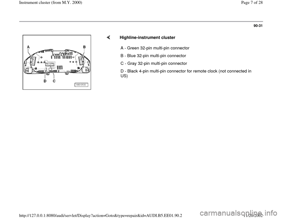
Highline-instrument cluster
A - Green 32-pin multi-pin connector
B - Blue 32-pin multi-pin connector
C - Gray 32-pin multi-pin connector
D - Black 4-pin multi-pin connector for remote clock (not connected in
US)
Pa
ge 7 of 28 Instrument cluster
(from M.Y. 2000
)
11/20/2002 htt
p://127.0.0.1:8080/audi/servlet/Dis
play?action=Goto&t
yp
e=re
pair&id=AUDI.B5.EE01.90.2
Page 8 of 28
90-32
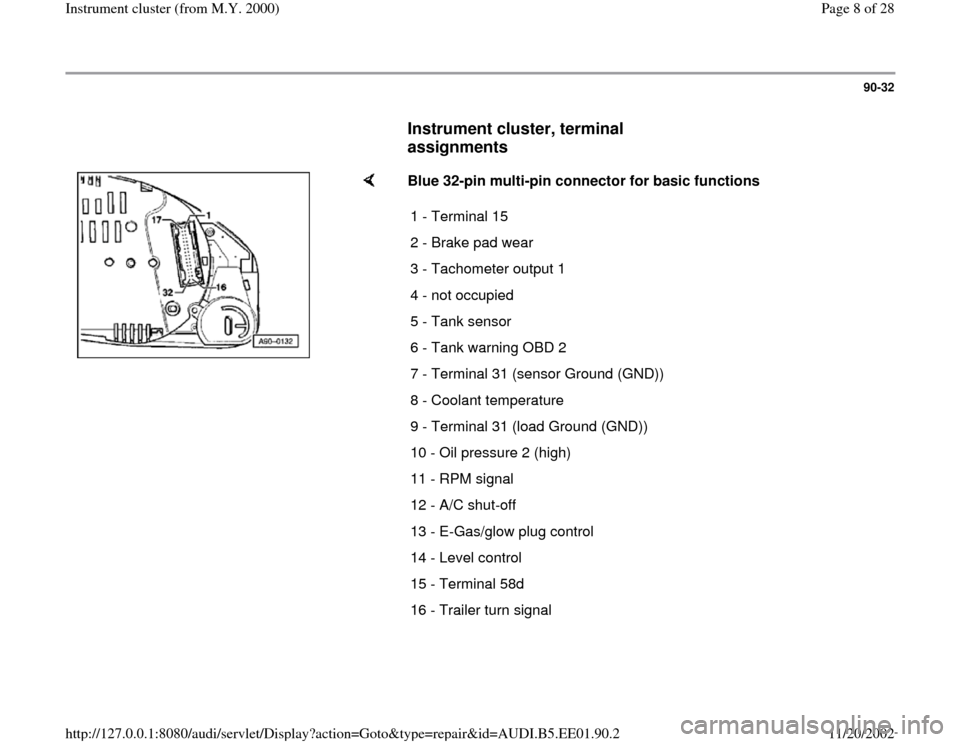
Instrument cluster, terminal
assignments
Blue 32-pin multi-pin connector for basic functions
1 - Terminal 15
2 - Brake pad wear
3 - Tachometer output 1
4 - not occupied
5 - Tank sensor
6 - Tank warning OBD 2
7 - Terminal 31 (sensor Ground (GND))
8 - Coolant temperature
9 - Terminal 31 (load Ground (GND))
10 - Oil pressure 2 (high)
11 - RPM signal
12 - A/C shut-off
13 - E-Gas/glow plug control
14 - Level control
15 - Terminal 58d
16 - Trailer turn signal
Pa
ge 8 of 28 Instrument cluster
(from M.Y. 2000
)
11/20/2002 htt
p://127.0.0.1:8080/audi/servlet/Dis
play?action=Goto&t
yp
e=re
pair&id=AUDI.B5.EE01.90.2
Page 9 of 28
90-33
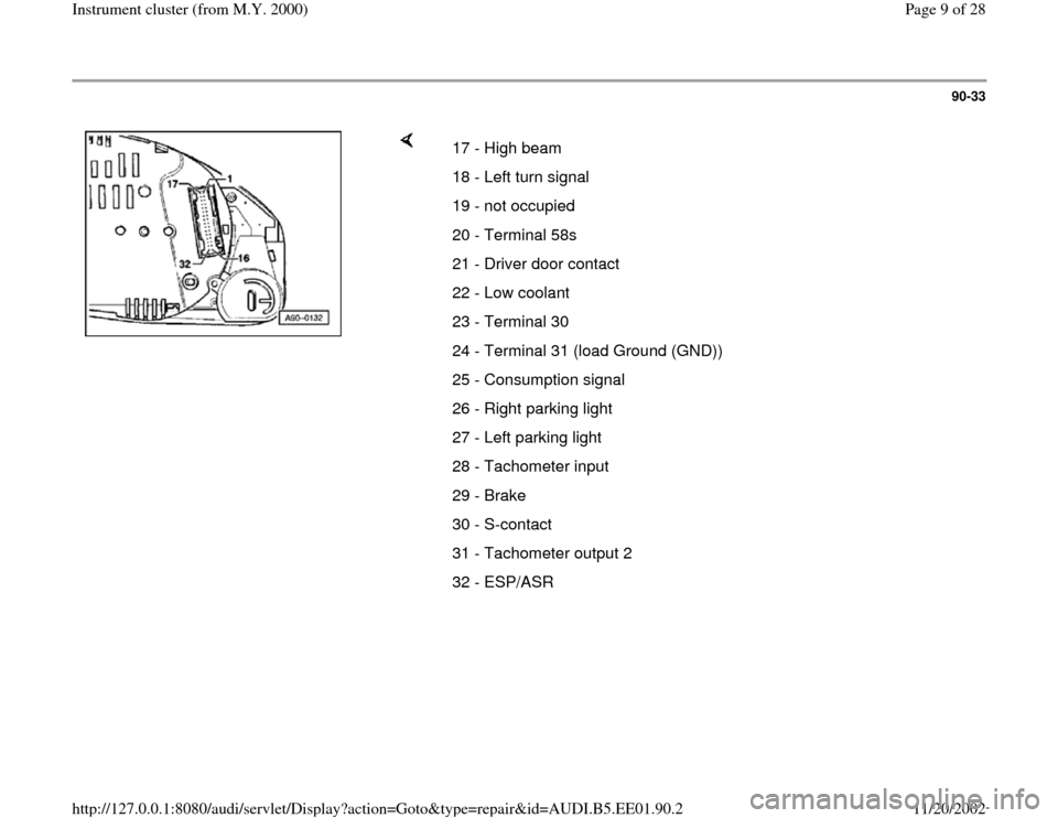
17 - High beam
18 - Left turn signal
19 - not occupied
20 - Terminal 58s
21 - Driver door contact
22 - Low coolant
23 - Terminal 30
24 - Terminal 31 (load Ground (GND))
25 - Consumption signal
26 - Right parking light
27 - Left parking light
28 - Tachometer input
29 - Brake
30 - S-contact
31 - Tachometer output 2
32 - ESP/ASR
Pa
ge 9 of 28 Instrument cluster
(from M.Y. 2000
)
11/20/2002 htt
p://127.0.0.1:8080/audi/servlet/Dis
play?action=Goto&t
yp
e=re
pair&id=AUDI.B5.EE01.90.2
Page 10 of 28
90-34
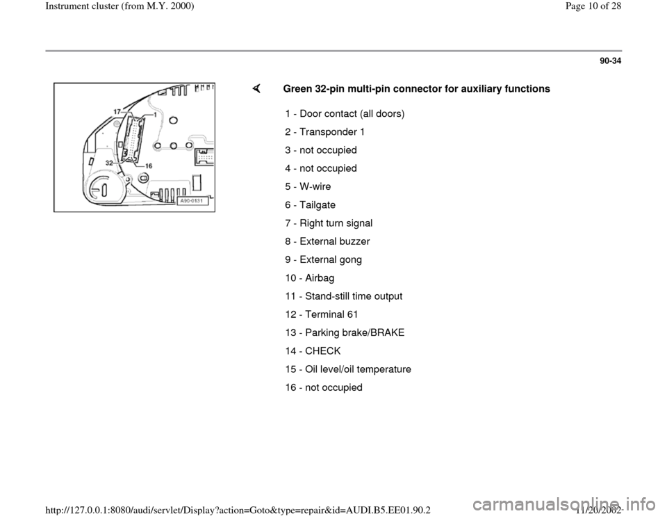
Green 32-pin multi-pin connector for auxiliary functions
1 - Door contact (all doors)
2 - Transponder 1
3 - not occupied
4 - not occupied
5 - W-wire
6 - Tailgate
7 - Right turn signal
8 - External buzzer
9 - External gong
10 - Airbag
11 - Stand-still time output
12 - Terminal 61
13 - Parking brake/BRAKE
14 - CHECK
15 - Oil level/oil temperature
16 - not occupied
Pa
ge 10 of 28 Instrument cluster
(from M.Y. 2000
)
11/20/2002 htt
p://127.0.0.1:8080/audi/servlet/Dis
play?action=Goto&t
yp
e=re
pair&id=AUDI.B5.EE01.90.2
Trending: warning, tow, remote control, reset, turn signal, fuel, low oil pressure
