checking AUDI A4 2000 B5 / 1.G ATW Engine Ignition System User Guide
[x] Cancel search | Manufacturer: AUDI, Model Year: 2000, Model line: A4, Model: AUDI A4 2000 B5 / 1.GPages: 59, PDF Size: 0.53 MB
Page 31 of 59
28-30
Engine Coolant Temperature (ECT) sensor
-G62-, checking
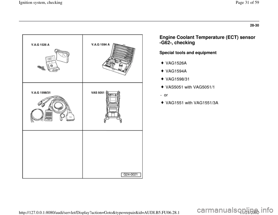
Special tools and equipment
VAG1526A
VAG1594A
VAG1598/31
VAS5051 with VAG5051/1
- or
VAG1551 with VAG1551/3A
Pa
ge 31 of 59 I
gnition s
ystem, checkin
g
11/21/2002 htt
p://127.0.0.1:8080/audi/servlet/Dis
play?action=Goto&t
yp
e=re
pair&id=AUDI.B5.FU06.28.1
Page 37 of 59
28-36
Voltage supply for control module,
checking
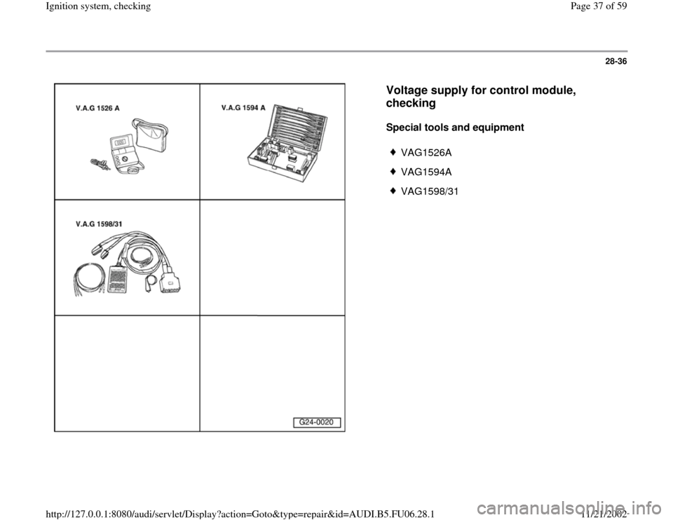
Special tools and equipment
VAG1526A
VAG1594A
VAG1598/31
Pa
ge 37 of 59 I
gnition s
ystem, checkin
g
11/21/2002 htt
p://127.0.0.1:8080/audi/servlet/Dis
play?action=Goto&t
yp
e=re
pair&id=AUDI.B5.FU06.28.1
Page 44 of 59
28-40
Knock recognition control stop,
checking
If a DTC is stored regarding "Knock control
regulation limit reached":
- Perform following tests:
Possible cause
Corrective action
DTC for all cylinders
Poor fuel quality
Operating instructions - Change fuel quality
or
Cylinder 1/2 or 3/4
Knock sensor tightened to incorrect torque- Loosen knock sensors and tighten to 20 Nm
Knock sensor faulty- Check knock sensor Page 28
-41
Corrosion at harness connector- Check harness connector
Engine accessories loose- Secure engine accessories
DTC for one Cylinder
Engine damage- Check compression pressure
Engine accessories loose- Secure engine accessories
Pa
ge 44 of 59 I
gnition s
ystem, checkin
g
11/21/2002 htt
p://127.0.0.1:8080/audi/servlet/Dis
play?action=Goto&t
yp
e=re
pair&id=AUDI.B5.FU06.28.1
Page 45 of 59
28-41
Knock sensors, checking
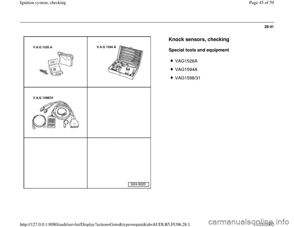
Special tools and equipment
VAG1526A
VAG1594A
VAG1598/31
Pa
ge 45 of 59 I
gnition s
ystem, checkin
g
11/21/2002 htt
p://127.0.0.1:8080/audi/servlet/Dis
play?action=Goto&t
yp
e=re
pair&id=AUDI.B5.FU06.28.1
Page 46 of 59
28-42
Component location Overview of component
locations Page 24
-5
Note:
Knock Sensor (KS) 1 -G61- and Knock Sensor
(KS) 2 -G66- themselves cannot be electrically
tested.
Use only gold-plated terminals when servicing
harness connector for knock sensors.
For the knock sensors to function properly, it is
important that tightening torque be exactly 20
Nm.
Check harness connector from knock sensor to
wiring harness for corrosion.
Checking knock sensor wiring
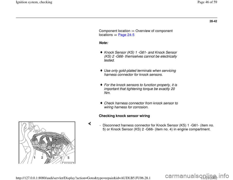
- Disconnect harness connector for Knock Sensor (KS) 1 -G61- (item no.
5) or Knock Sensor (KS) 2 -G66- (item no. 4) in engine compartment.
Pa
ge 46 of 59 I
gnition s
ystem, checkin
g
11/21/2002 htt
p://127.0.0.1:8080/audi/servlet/Dis
play?action=Goto&t
yp
e=re
pair&id=AUDI.B5.FU06.28.1
Page 49 of 59
28-45
Camshaft Position (CMP) sensor 2 -G40-,
checking
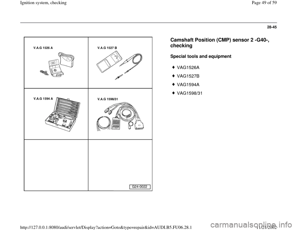
Special tools and equipment
VAG1526A
VAG1527B
VAG1594A
VAG1598/31
Pa
ge 49 of 59 I
gnition s
ystem, checkin
g
11/21/2002 htt
p://127.0.0.1:8080/audi/servlet/Dis
play?action=Goto&t
yp
e=re
pair&id=AUDI.B5.FU06.28.1
Page 51 of 59
28-47
Checking activation
- If installed, slide back rubber grommet on
connector for Camshaft Position (CMP) sensor,
but leave connector connected.
Note:
Connector socket numbers are shown on the rear side of the connector.
Note:
Voltage testers do not go out completely during low current pick-up
between activations by the ECM, but rather continue to glow a little and
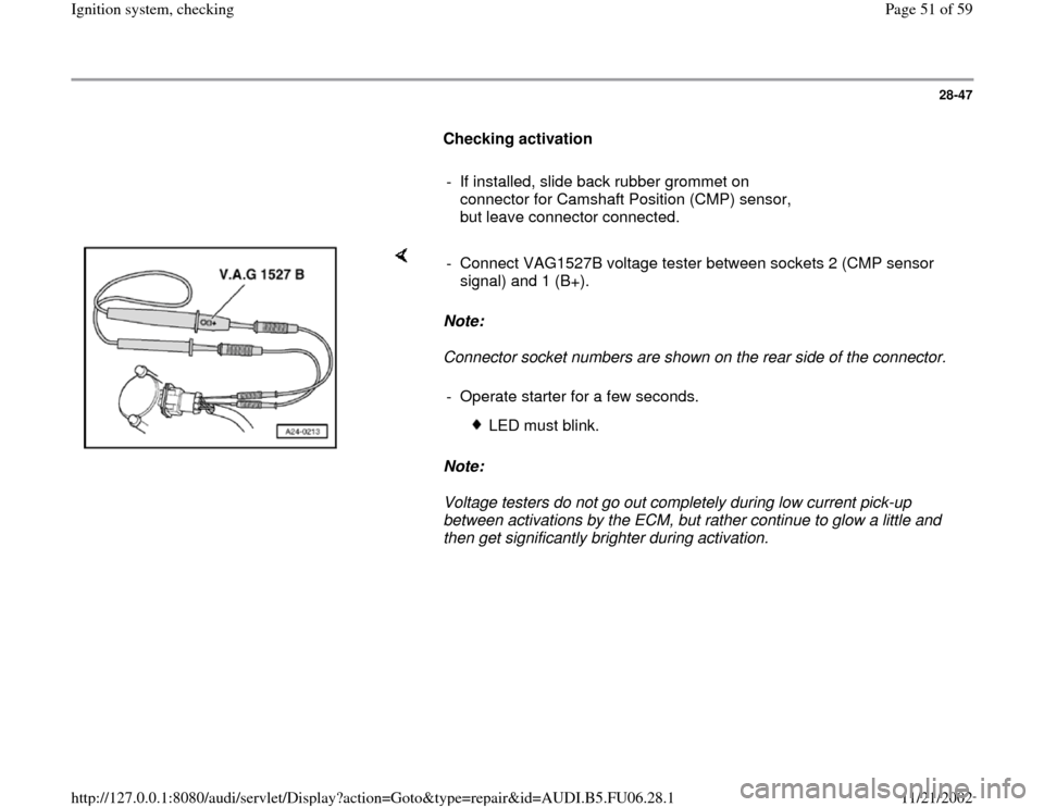
then get significantly brighter during activation. - Connect VAG1527B voltage tester between sockets 2 (CMP sensor
signal) and 1 (B+).
- Operate starter for a few seconds.
LED must blink.
Pa
ge 51 of 59 I
gnition s
ystem, checkin
g
11/21/2002 htt
p://127.0.0.1:8080/audi/servlet/Dis
play?action=Goto&t
yp
e=re
pair&id=AUDI.B5.FU06.28.1
Page 52 of 59
28-48
If LED does not blink:
Checking voltage supply
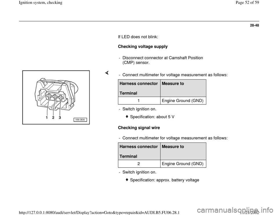
- Disconnect connector at Camshaft Position
(CMP) sensor.
Checking signal wire - Connect multimeter for voltage measurement as follows:Harness connector
Terminal
Measure to
1 Engine Ground (GND)
- Switch ignition on.
Specification: about 5 V
- Connect multimeter for voltage measurement as follows:
Harness connector
Terminal
Measure to
2 Engine Ground (GND)
- Switch ignition on.
Specification: approx. battery voltage
Pa
ge 52 of 59 I
gnition s
ystem, checkin
g
11/21/2002 htt
p://127.0.0.1:8080/audi/servlet/Dis
play?action=Goto&t
yp
e=re
pair&id=AUDI.B5.FU06.28.1
Page 53 of 59
28-49
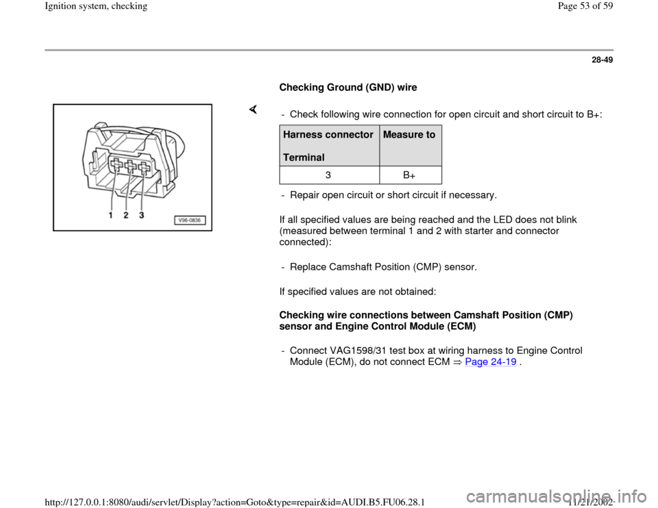
Checking Ground (GND) wire
If all specified values are being reached and the LED does not blink
(measured between terminal 1 and 2 with starter and connector
connected):
If specified values are not obtained:
Checking wire connections between Camshaft Position (CMP)
sensor and Engine Control Module (ECM) - Check following wire connection for open circuit and short circuit to B+:Harness connector
Terminal
Measure to
3 B+
- Repair open circuit or short circuit if necessary.
- Replace Camshaft Position (CMP) sensor.
- Connect VAG1598/31 test box at wiring harness to Engine Control
Module (ECM), do not connect ECM Page 24
-19
.
Pa
ge 53 of 59 I
gnition s
ystem, checkin
g
11/21/2002 htt
p://127.0.0.1:8080/audi/servlet/Dis
play?action=Goto&t
yp
e=re
pair&id=AUDI.B5.FU06.28.1
Page 55 of 59
28-51
Misfire recognition, checking
Special tools and equipment
Test sequence
VAS5051 with VAG5051/1
orVAG1551 with VAG1551/3A
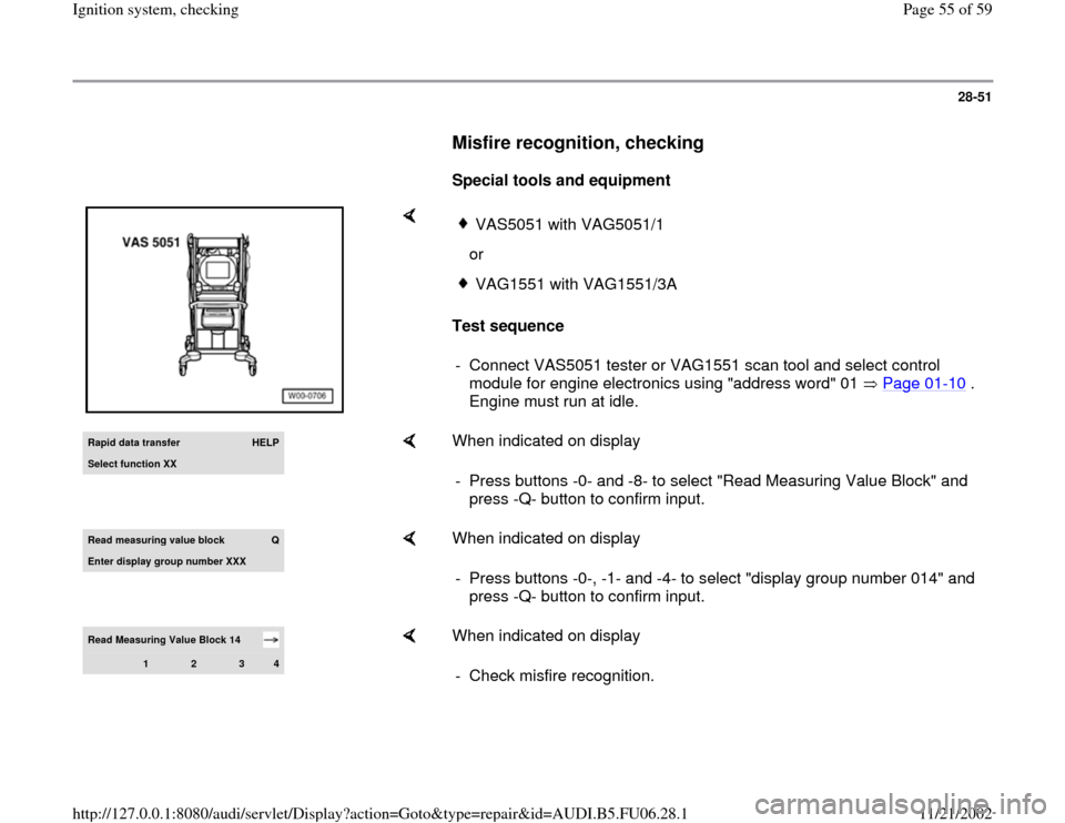
- Connect VAS5051 tester or VAG1551 scan tool and select control
module for engine electronics using "address word" 01 Page 01
-10
.
Engine must run at idle.
Rapid data transfer
HELP
Select function XX
When indicated on display
- Press buttons -0- and -8- to select "Read Measuring Value Block" and
press -Q- button to confirm input.
Read measurin
g value block
Q
Enter displa
y group number XXX
When indicated on display
- Press buttons -0-, -1- and -4- to select "display group number 014" and
press -Q- button to confirm input.
Read Measuring Value Block 14
1
2
3
4
When indicated on display
- Check misfire recognition.
Pa
ge 55 of 59 I
gnition s
ystem, checkin
g
11/21/2002 htt
p://127.0.0.1:8080/audi/servlet/Dis
play?action=Goto&t
yp
e=re
pair&id=AUDI.B5.FU06.28.1