AUDI A4 2000 B5 / 1.G ATW Engine Ignition System Workshop Manual
A4 2000 B5 / 1.G
AUDI
AUDI
https://www.carmanualsonline.info/img/6/1077/w960_1077-0.png
AUDI A4 2000 B5 / 1.G ATW Engine Ignition System Workshop Manual
Page 1 of 59
28-1
Ignition system, checking
General notes on ignition system
Note:
The battery should only be disconnected and
reconnected when the ignition is turned off,
since otherwise the Engine Control Module
(ECM) can be damaged.
For the electric components to work properly, a
voltage of at least 12.7 V is required.
It is possible that the control module will
recognize a malfunction and store a DTC during
some tests. After completing all tests and
repairs, DTC memory should therefore be
checked and erased if necessary.
If the engine only starts briefly and then turns
off again after troubleshooting, repair or
checking of the components, it may be that the
immobilizer is blocking the Engine Control
Module (ECM). DTC memory must then be
checked and if necessary, control module must
be adapted.
Pa
ge 1 of 59 I
gnition s
ystem, checkin
g
11/21/2002 htt
p://127.0.0.1:8080/audi/servlet/Dis
play?action=Goto&t
yp
e=re
pair&id=AUDI.B5.FU06.28.1
Page 4 of 59
28-4
Ignition coils with power output stages,
checking
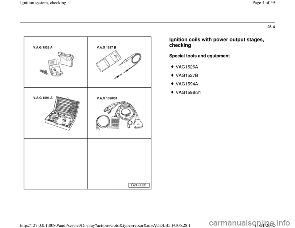
Special tools and equipment
VAG1526A
VAG1527B
VAG1594A
VAG1598/31
Pa
ge 4 of 59 I
gnition s
ystem, checkin
g
11/21/2002 htt
p://127.0.0.1:8080/audi/servlet/Dis
play?action=Goto&t
yp
e=re
pair&id=AUDI.B5.FU06.28.1
Page 8 of 59
28-7
If LED does not light up:
Electrical Wiring Diagrams, Troubleshooting & Component Locations
If LED lights up:
Checking voltage supply
Test requirement:
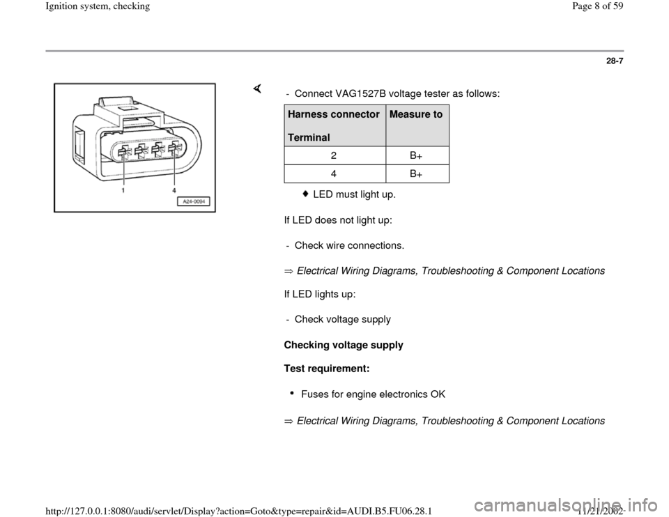
Electrical Wiring Diagrams, Troubleshooting & Component Locations - Connect VAG1527B voltage tester as follows:Harness connector
Terminal
Measure to
2 B+
4 B+
LED must light up.
- Check wire connections.
- Check voltage supply
Fuses for engine electronics OK
Pa
ge 8 of 59 I
gnition s
ystem, checkin
g
11/21/2002 htt
p://127.0.0.1:8080/audi/servlet/Dis
play?action=Goto&t
yp
e=re
pair&id=AUDI.B5.FU06.28.1
Page 11 of 59
28-10
- Perform following tests marked with dots:
Checking activation of power output stages
Note:
Fuel must not be injected during the test to avoid damaging catalytic
converter. Connectors must therefore be disconnected from fuel injectors.
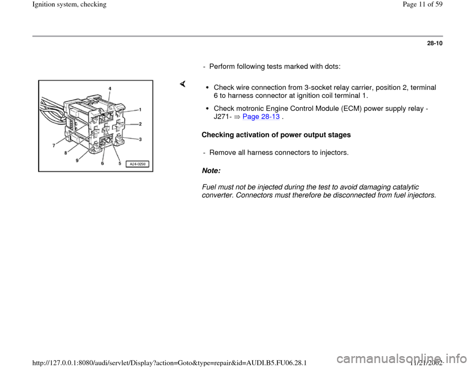
Check wire connection from 3-socket relay carrier, position 2, terminal
6 to harness connector at ignition coil terminal 1. Check motronic Engine Control Module (ECM) power supply relay -
J271- Page 28
-13
.
- Remove all harness connectors to injectors.
Pa
ge 11 of 59 I
gnition s
ystem, checkin
g
11/21/2002 htt
p://127.0.0.1:8080/audi/servlet/Dis
play?action=Goto&t
yp
e=re
pair&id=AUDI.B5.FU06.28.1
Page 14 of 59
28-13
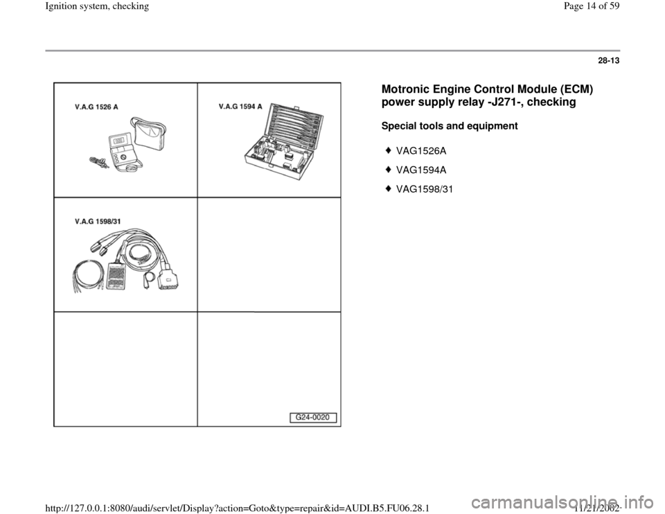
Motronic Engine Control Module (ECM)
power supply relay -J271-, checking
Special tools and equipment
VAG1526A
VAG1594A
VAG1598/31
Pa
ge 14 of 59 I
gnition s
ystem, checkin
g
11/21/2002 htt
p://127.0.0.1:8080/audi/servlet/Dis
play?action=Goto&t
yp
e=re
pair&id=AUDI.B5.FU06.28.1
Page 19 of 59
28-18
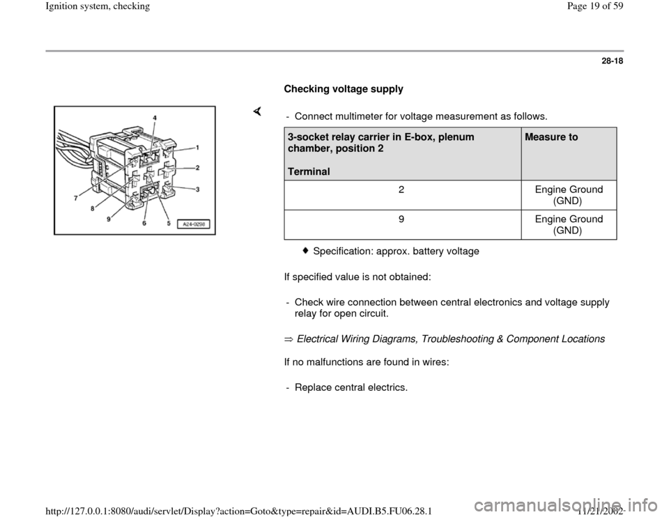
Checking voltage supply
If specified value is not obtained:
Electrical Wiring Diagrams, Troubleshooting & Component Locations
If no malfunctions are found in wires: - Connect multimeter for voltage measurement as follows.3-socket relay carrier in E-box, plenum
chamber, position 2
Terminal
Measure to
2 Engine Ground
(GND)
9 Engine Ground
(GND)
Specification: approx. battery voltage
- Check wire connection between central electronics and voltage supply
relay for open circuit.
- Replace central electrics.
Pa
ge 19 of 59 I
gnition s
ystem, checkin
g
11/21/2002 htt
p://127.0.0.1:8080/audi/servlet/Dis
play?action=Goto&t
yp
e=re
pair&id=AUDI.B5.FU06.28.1
Page 20 of 59
28-19
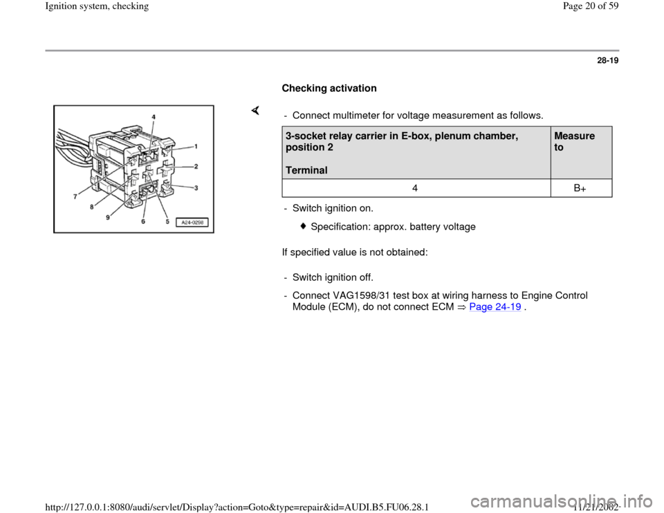
Checking activation
If specified value is not obtained: - Connect multimeter for voltage measurement as follows.3-socket relay carrier in E-box, plenum chamber,
position 2
Terminal
Measure
to
4 B+
- Switch ignition on.
Specification: approx. battery voltage
- Switch ignition off.
- Connect VAG1598/31 test box at wiring harness to Engine Control
Module (ECM), do not connect ECM Page 24
-19
.
Pa
ge 20 of 59 I
gnition s
ystem, checkin
g
11/21/2002 htt
p://127.0.0.1:8080/audi/servlet/Dis
play?action=Goto&t
yp
e=re
pair&id=AUDI.B5.FU06.28.1
Page 22 of 59
28-21
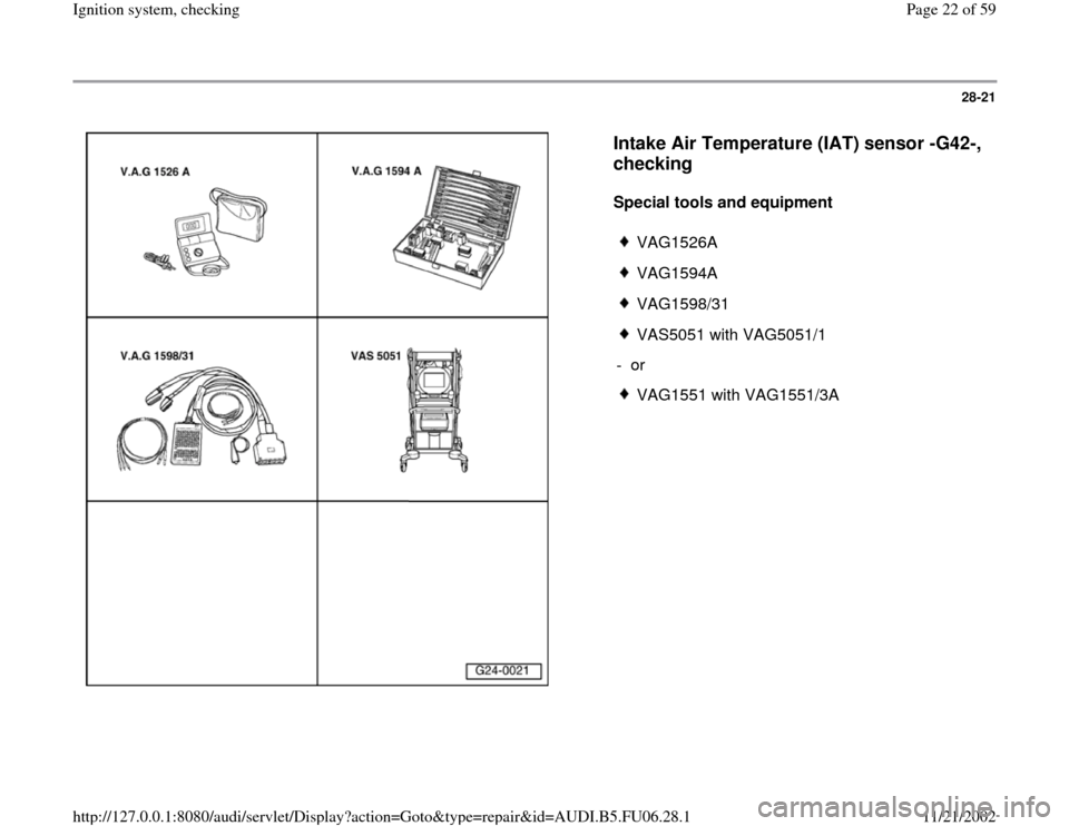
Intake Air Temperature (IAT) sensor -G42-,
checking
Special tools and equipment
VAG1526A
VAG1594A
VAG1598/31
VAS5051 with VAG5051/1
- or
VAG1551 with VAG1551/3A
Pa
ge 22 of 59 I
gnition s
ystem, checkin
g
11/21/2002 htt
p://127.0.0.1:8080/audi/servlet/Dis
play?action=Goto&t
yp
e=re
pair&id=AUDI.B5.FU06.28.1
Page 25 of 59
28-24
Checking wire connections
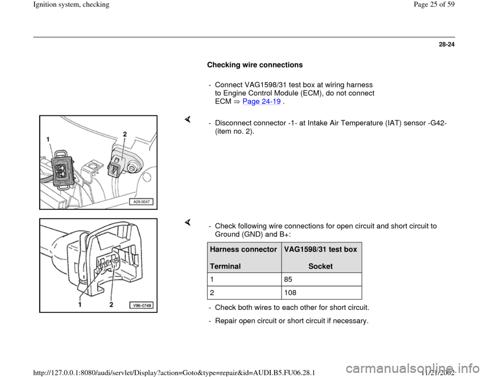
- Connect VAG1598/31 test box at wiring harness
to Engine Control Module (ECM), do not connect
ECM Page 24
-19
.
- Disconnect connector -1- at Intake Air Temperature (IAT) sensor -G42-
(item no. 2).
- Check following wire connections for open circuit and short circuit to
Ground (GND) and B+: Harness connector
Terminal
VAG1598/31 test box
Socket
1 85
2 108
- Check both wires to each other for short circuit.
- Repair open circuit or short circuit if necessary.
Pa
ge 25 of 59 I
gnition s
ystem, checkin
g
11/21/2002 htt
p://127.0.0.1:8080/audi/servlet/Dis
play?action=Goto&t
yp
e=re
pair&id=AUDI.B5.FU06.28.1
Page 27 of 59
28-26
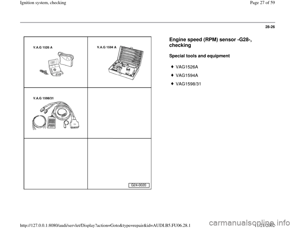
Engine speed (RPM) sensor -G28-,
checking
Special tools and equipment
VAG1526A
VAG1594A
VAG1598/31
Pa
ge 27 of 59 I
gnition s
ystem, checkin
g
11/21/2002 htt
p://127.0.0.1:8080/audi/servlet/Dis
play?action=Goto&t
yp
e=re
pair&id=AUDI.B5.FU06.28.1