lock AUDI A4 2000 B5 / 1.G AWM Engine Exhaust System Components Workshop Manual
[x] Cancel search | Manufacturer: AUDI, Model Year: 2000, Model line: A4, Model: AUDI A4 2000 B5 / 1.GPages: 41, PDF Size: 0.7 MB
Page 1 of 41
26-1
Exhaust system components,
removing and installing
Note:
Always replace seals, gaskets and self-locking
nuts.
After working on the exhaust system ensure
that the system is not under stress, and that it
has sufficient clearance from the bodywork. If
necessary, loosen clamps and align mufflers
and exhaust pipes so that sufficient clearance is
maintained to the bodywork at all points and the
mountings are evenly loaded.
The flexible connection in the front exhaust pipe
must not be deflected more than 10 or it may
be damaged..
Pa
ge 1 of 41 Exhaust s
ystem com
ponents, removin
g and installin
g
11/21/2002 htt
p://127.0.0.1:8080/audi/servlet/Dis
play?action=Goto&t
yp
e=re
pair&id=AUDI.B5.GE06.26.1
Page 16 of 41
26-16
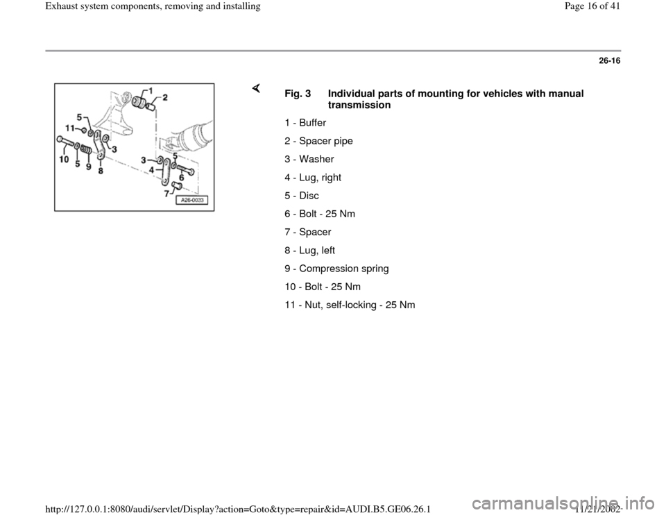
Fig. 3 Individual parts of mounting for vehicles with manual
transmission
1 - Buffer
2 - Spacer pipe
3 - Washer
4 - Lug, right
5 - Disc
6 - Bolt - 25 Nm
7 - Spacer
8 - Lug, left
9 - Compression spring
10 - Bolt - 25 Nm
11 - Nut, self-locking - 25 Nm
Pa
ge 16 of 41 Exhaust s
ystem com
ponents, removin
g and installin
g
11/21/2002 htt
p://127.0.0.1:8080/audi/servlet/Dis
play?action=Goto&t
yp
e=re
pair&id=AUDI.B5.GE06.26.1
Page 17 of 41
26-17
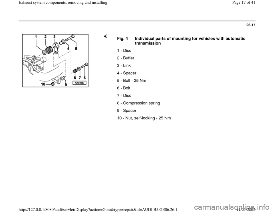
Fig. 4 Individual parts of mounting for vehicles with automatic
transmission
1 - Disc
2 - Buffer
3 - Link
4 - Spacer
5 - Bolt - 25 Nm
6 - Bolt
7 - Disc
8 - Compression spring
9 - Spacer
10 - Nut, self-locking - 25 Nm
Pa
ge 17 of 41 Exhaust s
ystem com
ponents, removin
g and installin
g
11/21/2002 htt
p://127.0.0.1:8080/audi/servlet/Dis
play?action=Goto&t
yp
e=re
pair&id=AUDI.B5.GE06.26.1
Page 25 of 41
26-25
Installing
Installation is carried out in the reverse order of removal; note the
following:
Note:
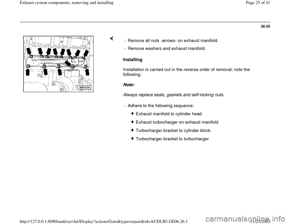
Always replace seals, gaskets and self-locking nuts. - Remove all nuts -arrows- on exhaust manifold.
- Remove washers and exhaust manifold.
- Adhere to the following sequence:
Exhaust manifold to cylinder head
Exhaust turbocharger on exhaust manifold
Turbocharger bracket to cylinder block
Turbocharger bracket to turbocharger
Pa
ge 25 of 41 Exhaust s
ystem com
ponents, removin
g and installin
g
11/21/2002 htt
p://127.0.0.1:8080/audi/servlet/Dis
play?action=Goto&t
yp
e=re
pair&id=AUDI.B5.GE06.26.1
Page 26 of 41
26-26
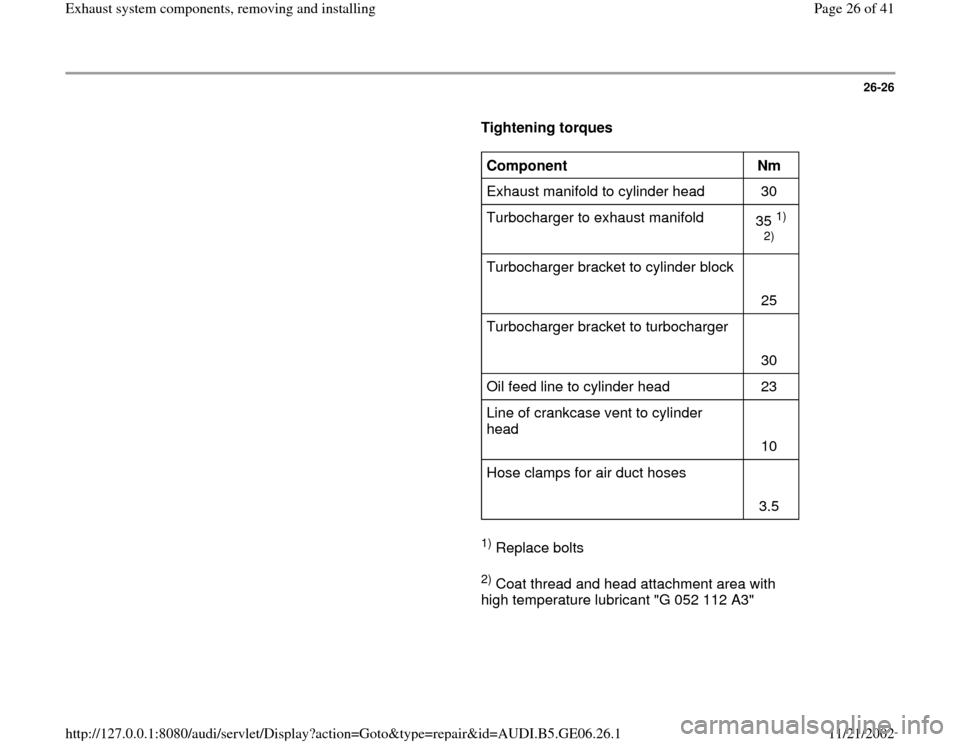
Tightening torques
Component
Nm
Exhaust manifold to cylinder head 30
Turbocharger to exhaust manifold
35
1)
2)
Turbocharger bracket to cylinder block
25
Turbocharger bracket to turbocharger
30
Oil feed line to cylinder head 23
Line of crankcase vent to cylinder
head
10
Hose clamps for air duct hoses
3.5
1) Replace bolts
2) Coat thread and head attachment area with
high temperature lubricant "G 052 112 A3"
Pa
ge 26 of 41 Exhaust s
ystem com
ponents, removin
g and installin
g
11/21/2002 htt
p://127.0.0.1:8080/audi/servlet/Dis
play?action=Goto&t
yp
e=re
pair&id=AUDI.B5.GE06.26.1
Page 31 of 41
26-31
Installing
Installation is carried out in the reverse order of
removal; note the following:
Note:
Always replace seals, gaskets and self-locking
nuts.
- Grease threads of oxygen sensors with high
temperature lubricant G 052 112 A3. Apply
lubricant only to threads of sensors; the lubricant
must not get into the slots on the sensor body.
- Align exhaust system stress-free Page 26
-34
or Page 26
-37
.
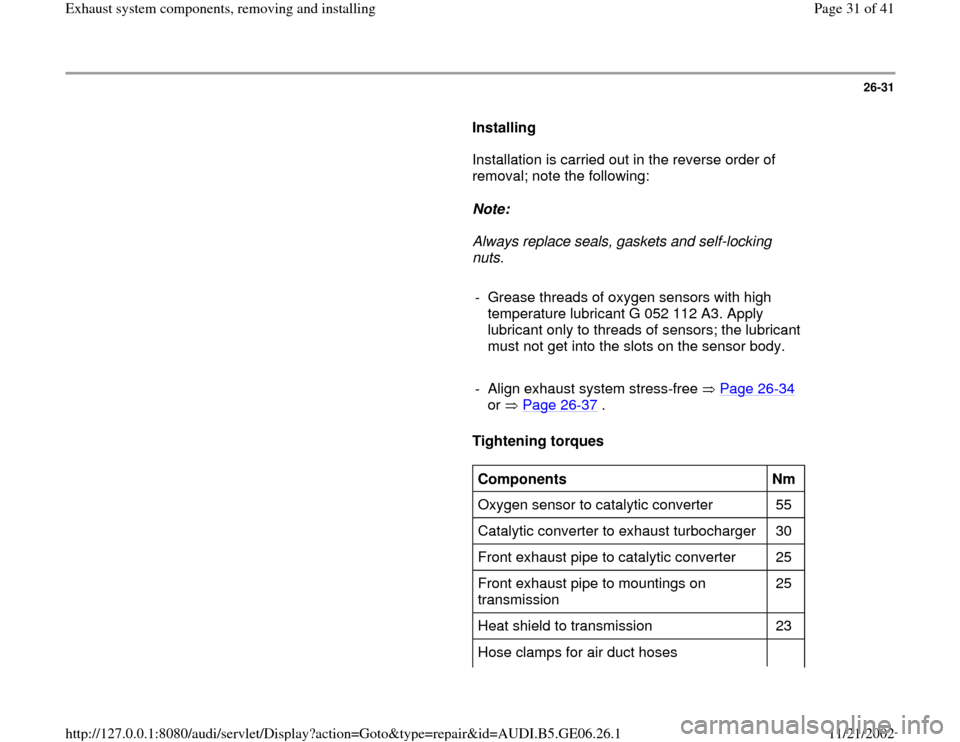
Tightening torques
Components
Nm
Oxygen sensor to catalytic converter 55
Catalytic converter to exhaust turbocharger 30
Front exhaust pipe to catalytic converter 25
Front exhaust pipe to mountings on
transmission 25
Heat shield to transmission 23
Hose clamps for air duct hoses
Pa
ge 31 of 41 Exhaust s
ystem com
ponents, removin
g and installin
g
11/21/2002 htt
p://127.0.0.1:8080/audi/servlet/Dis
play?action=Goto&t
yp
e=re
pair&id=AUDI.B5.GE06.26.1
Page 34 of 41
26-33
Note:
The flexible connection in the front exhaust pipe
must not be deflected more than 10 or it may
be damaged.
Installing
Installation is carried out in the reverse order of removal; note the
following:
Note:
Always replace seals, gaskets and self-locking nuts.
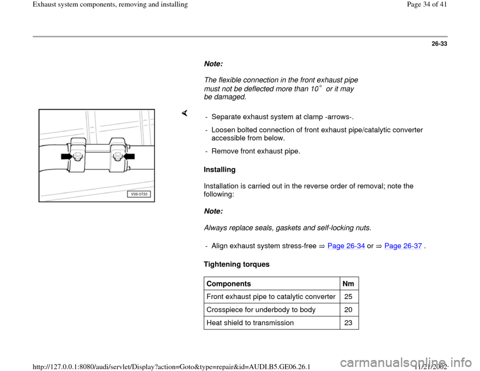
Tightening torques - Separate exhaust system at clamp -arrows-.
- Loosen bolted connection of front exhaust pipe/catalytic converter
accessible from below.
- Remove front exhaust pipe.
- Align exhaust system stress-free Page 26
-34
or Page 26
-37
.
Components
Nm
Front exhaust pipe to catalytic converter 25
Crosspiece for underbody to body 20
Heat shield to transmission 23
Pa
ge 34 of 41 Exhaust s
ystem com
ponents, removin
g and installin
g
11/21/2002 htt
p://127.0.0.1:8080/audi/servlet/Dis
play?action=Goto&t
yp
e=re
pair&id=AUDI.B5.GE06.26.1