ignition AUDI A4 2000 B5 / 1.G AWM Engine Motronic Injection System Servicing Workshop Manual
[x] Cancel search | Manufacturer: AUDI, Model Year: 2000, Model line: A4, Model: AUDI A4 2000 B5 / 1.GPages: 79, PDF Size: 1.04 MB
Page 1 of 79
24-1
Motronic injection system,
servicing
Safety precautions
If special testing equipment is required during
road test, note the following:
WARNING!
Test equipment must always be secured to
the rear seat and operated from there by a
second person.
If test and measuring equipment is operated
from the passenger seat, the person seated
there could be injured in the event of an
accident involving deployment of the
passenger-side airbag.
To reduce the risk of personal injury and/or
damage to the fuel injection and ignition system,
always observe the following:
Only disconnect and reconnect wires for
injection and ignition system, including test
leads, when ignition is turned off.
If engine is to be cranked at starting RPM
without starting (e.g. for compression testing),
Pa
ge 1 of 79 Motronic in
jection s
ystem, servicin
g
11/22/2002 htt
p://127.0.0.1:8080/audi/servlet/Dis
play?action=Goto&t
yp
e=re
pair&id=AUDI.B5.FU07.24.1
Page 2 of 79
disconnect connector from ignition coils and
from fuel injectors.
Pa
ge 2 of 79 Motronic in
jection s
ystem, servicin
g
11/22/2002 htt
p://127.0.0.1:8080/audi/servlet/Dis
play?action=Goto&t
yp
e=re
pair&id=AUDI.B5.FU07.24.1
Page 3 of 79
24-2
It is possible that the control module will
recognize a malfunction and store a DTC during
some tests. After completing all tests and
repairs, DTC memory should therefore be
checked and erased if necessary. Readiness
code must be generated after DTC memory is
erased Page 01
-84
.
Always switch ignition off before cleaning
engine.
The battery should only be disconnected and
reconnected when the ignition is turned off,
since otherwise the Engine Control Module
(ECM) can be damaged.
WARNING!
Fuel system is under pressure! Before
opening system, place rags around the
connection point. Then release pressure by
carefully loosening connection.
Pa
ge 3 of 79 Motronic in
jection s
ystem, servicin
g
11/22/2002 htt
p://127.0.0.1:8080/audi/servlet/Dis
play?action=Goto&t
yp
e=re
pair&id=AUDI.B5.FU07.24.1
Page 14 of 79
24-12
Repair Manual, 1.8 Liter 4
-Cyl. 5V Turbo Engine
Mechanical, Engine Code(s): AWM, Repair Group 21, Charge air system with turbocharger, checking
Repair Manual, 1.8 Liter 4
-Cyl. 5V Turbo Engine
Mechanical, Engine Code(s): AWM, Repair Group 26; Secondary Air Injection (AIR) system, checking
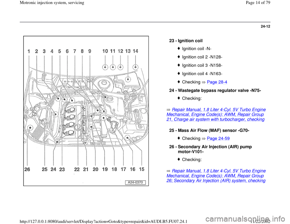
23 -
Ignition coil
Ignition coil -N-Ignition coil 2 -N128-Ignition coil 3 -N158-Ignition coil 4 -N163-Checking Page 28
-4
24 -
Wastegate bypass regulator valve -N75-
Checking:
25 -
Mass Air Flow (MAF) sensor -G70-
Checking Page 24
-59
26 -
Secondary Air Injection (AIR) pump
motor-V101-
Checking:
Pa
ge 14 of 79 Motronic in
jection s
ystem, servicin
g
11/22/2002 htt
p://127.0.0.1:8080/audi/servlet/Dis
play?action=Goto&t
yp
e=re
pair&id=AUDI.B5.FU07.24.1
Page 22 of 79
24-20
Special Tools and Equipment
Procedure
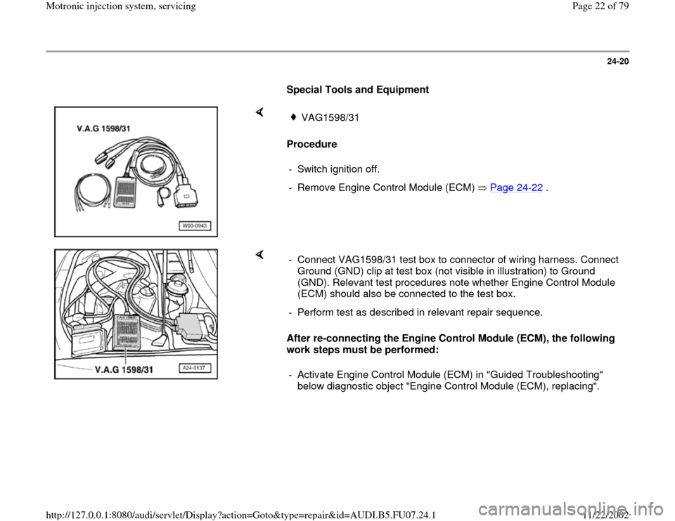
VAG1598/31
- Switch ignition off.
- Remove Engine Control Module (ECM) Page 24
-22
.
After re-connecting the Engine Control Module (ECM), the following
work steps must be performed: - Connect VAG1598/31 test box to connector of wiring harness. Connect
Ground (GND) clip at test box (not visible in illustration) to Ground
(GND). Relevant test procedures note whether Engine Control Module
(ECM) should also be connected to the test box.
- Perform test as described in relevant repair sequence.
- Activate Engine Control Module (ECM) in "Guided Troubleshooting"
below diagnostic object "Engine Control Module (ECM), replacing".
Pa
ge 22 of 79 Motronic in
jection s
ystem, servicin
g
11/22/2002 htt
p://127.0.0.1:8080/audi/servlet/Dis
play?action=Goto&t
yp
e=re
pair&id=AUDI.B5.FU07.24.1
Page 24 of 79
24-22
Engine Control Module (ECM), replacing
Special Tools and Equipment
Removing
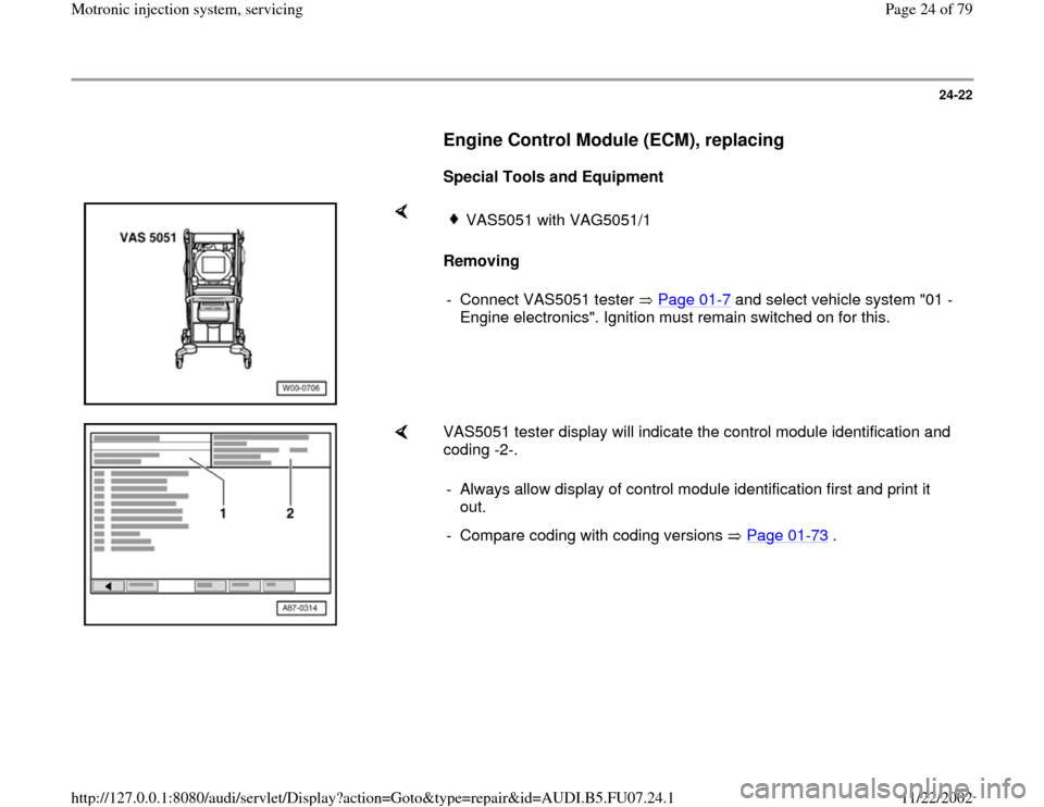
VAS5051 with VAG5051/1
- Connect VAS5051 tester Page 01
-7 and select vehicle system "01 -
Engine electronics". Ignition must remain switched on for this.
VAS5051 tester display will indicate the control module identification and
coding -2-.
- Always allow display of control module identification first and print it
out.
- Compare coding with coding versions Page 01
-73
.
Pa
ge 24 of 79 Motronic in
jection s
ystem, servicin
g
11/22/2002 htt
p://127.0.0.1:8080/audi/servlet/Dis
play?action=Goto&t
yp
e=re
pair&id=AUDI.B5.FU07.24.1
Page 25 of 79
24-23
- Switch ignition off.
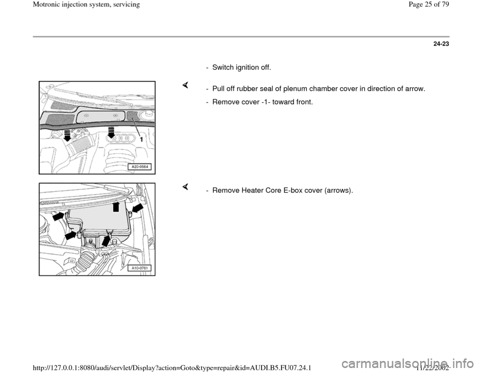
- Pull off rubber seal of plenum chamber cover in direction of arrow.
- Remove cover -1- toward front.
- Remove Heater Core E-box cover (arrows).
Pa
ge 25 of 79 Motronic in
jection s
ystem, servicin
g
11/22/2002 htt
p://127.0.0.1:8080/audi/servlet/Dis
play?action=Goto&t
yp
e=re
pair&id=AUDI.B5.FU07.24.1
Page 37 of 79
24-34
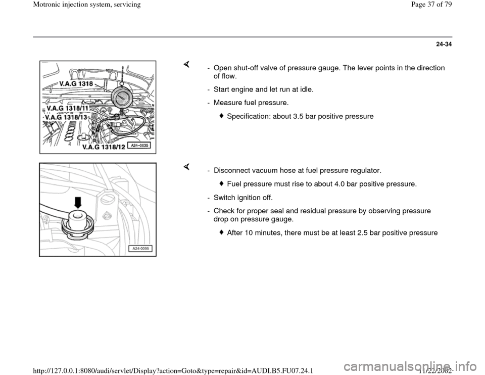
- Open shut-off valve of pressure gauge. The lever points in the direction
of flow.
- Start engine and let run at idle.
- Measure fuel pressure.
Specification: about 3.5 bar positive pressure
- Disconnect vacuum hose at fuel pressure regulator.
Fuel pressure must rise to about 4.0 bar positive pressure.
- Switch ignition off.
- Check for proper seal and residual pressure by observing pressure
drop on pressure gauge.
After 10 minutes, there must be at least 2.5 bar positive pressure
Pa
ge 37 of 79 Motronic in
jection s
ystem, servicin
g
11/22/2002 htt
p://127.0.0.1:8080/audi/servlet/Dis
play?action=Goto&t
yp
e=re
pair&id=AUDI.B5.FU07.24.1
Page 38 of 79
24-35
If residual pressure sinks below 2.5 bar positive
pressure:
- Start engine and let run at idle.
If pressure does not drop now:
If pressure drops again:
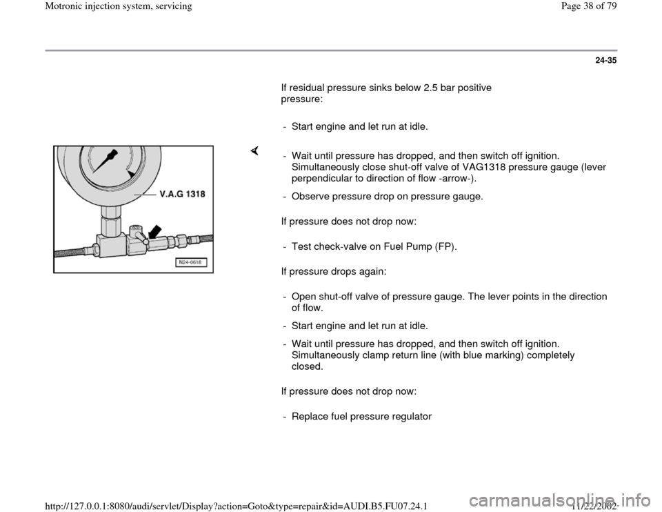
If pressure does not drop now: - Wait until pressure has dropped, and then switch off ignition.
Simultaneously close shut-off valve of VAG1318 pressure gauge (lever
perpendicular to direction of flow -arrow-).
- Observe pressure drop on pressure gauge.
- Test check-valve on Fuel Pump (FP).
- Open shut-off valve of pressure gauge. The lever points in the direction
of flow.
- Start engine and let run at idle.
- Wait until pressure has dropped, and then switch off ignition.
Simultaneously clamp return line (with blue marking) completely
closed.
- Replace fuel pressure regulator
Pa
ge 38 of 79 Motronic in
jection s
ystem, servicin
g
11/22/2002 htt
p://127.0.0.1:8080/audi/servlet/Dis
play?action=Goto&t
yp
e=re
pair&id=AUDI.B5.FU07.24.1
Page 42 of 79
24-39
Checking voltage supply
Test requirements:
Fuse for fuel injectors OK
Electrical Wiring Diagrams, Troubleshooting &
Component Locations
Fuel Pump (FP) relay OK; checking Page 24
-52
.
- Disconnect harness connector at the fuel
injector to be tested.
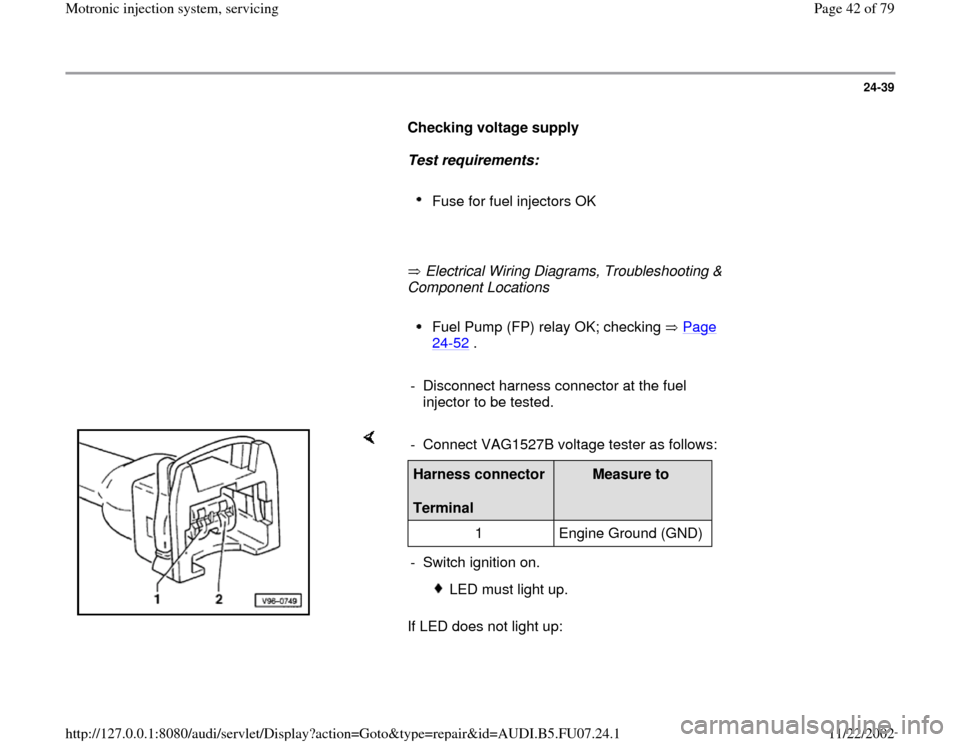
If LED does not light up: - Connect VAG1527B voltage tester as follows:Harness connector
Terminal
Measure to
1 Engine Ground (GND)
- Switch ignition on.
LED must light up.
Pa
ge 42 of 79 Motronic in
jection s
ystem, servicin
g
11/22/2002 htt
p://127.0.0.1:8080/audi/servlet/Dis
play?action=Goto&t
yp
e=re
pair&id=AUDI.B5.FU07.24.1