warning AUDI A4 2000 B5 / 1.G AWM Engine Motronic Injection System Servicing Workshop Manual
[x] Cancel search | Manufacturer: AUDI, Model Year: 2000, Model line: A4, Model: AUDI A4 2000 B5 / 1.GPages: 79, PDF Size: 1.04 MB
Page 1 of 79
24-1
Motronic injection system,
servicing
Safety precautions
If special testing equipment is required during
road test, note the following:
WARNING!
Test equipment must always be secured to
the rear seat and operated from there by a
second person.
If test and measuring equipment is operated
from the passenger seat, the person seated
there could be injured in the event of an
accident involving deployment of the
passenger-side airbag.
To reduce the risk of personal injury and/or
damage to the fuel injection and ignition system,
always observe the following:
Only disconnect and reconnect wires for
injection and ignition system, including test
leads, when ignition is turned off.
If engine is to be cranked at starting RPM
without starting (e.g. for compression testing),
Pa
ge 1 of 79 Motronic in
jection s
ystem, servicin
g
11/22/2002 htt
p://127.0.0.1:8080/audi/servlet/Dis
play?action=Goto&t
yp
e=re
pair&id=AUDI.B5.FU07.24.1
Page 3 of 79
24-2
It is possible that the control module will
recognize a malfunction and store a DTC during
some tests. After completing all tests and
repairs, DTC memory should therefore be
checked and erased if necessary. Readiness
code must be generated after DTC memory is
erased Page 01
-84
.
Always switch ignition off before cleaning
engine.
The battery should only be disconnected and
reconnected when the ignition is turned off,
since otherwise the Engine Control Module
(ECM) can be damaged.
WARNING!
Fuel system is under pressure! Before
opening system, place rags around the
connection point. Then release pressure by
carefully loosening connection.
Pa
ge 3 of 79 Motronic in
jection s
ystem, servicin
g
11/22/2002 htt
p://127.0.0.1:8080/audi/servlet/Dis
play?action=Goto&t
yp
e=re
pair&id=AUDI.B5.FU07.24.1
Page 9 of 79
24-8
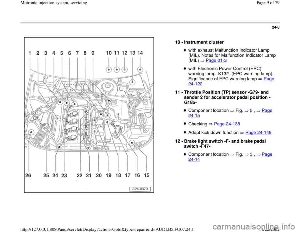
10 -
Instrument cluster
with exhaust Malfunction Indicator Lamp
(MIL). Notes for Malfunction Indicator Lamp
(MIL) Page 01
-3
with Electronic Power Control (EPC)
warning lamp -K132- (EPC warning lamp).
Significance of EPC warning lamp Page 24
-122
11 -
Throttle Position (TP) sensor -G79- and
sender 2 for accelerator pedal position -
G185-
Component location Fig. 5
, Page
24
-15
Checking Page 24
-138
Adapt kick down function Page 24
-145
12 -
Brake light switch -F- and brake pedal
switch -F47-
Component location Fig. 3
, Page
24
-14
Pa
ge 9 of 79 Motronic in
jection s
ystem, servicin
g
11/22/2002 htt
p://127.0.0.1:8080/audi/servlet/Dis
play?action=Goto&t
yp
e=re
pair&id=AUDI.B5.FU07.24.1
Page 21 of 79
24-19
Wire and component testing using
VAG1598/31 test box
Notes:
VAG1598/31 test box is designed so that it can
be simultaneously connected to the wiring
harness at the Engine Control Module (ECM)
and also to the ECM itself.
This is advantageous because electronic
engine control remains fully functional (e.g.
measurement of signals with engine running)
when the test box is attached.
Relevant test procedures note whether Engine
Control Module (ECM) should also be
connected to the test box or not.
Always use VAG1594A connector test kit to
attach measurement devices (e.g. VAG1527B
voltage tester, VAG1526 multimeter etc.).
WARNING!
To avoid damaging electronic components,
set measuring range before connecting test
leads and observe all test requirements.
Pa
ge 21 of 79 Motronic in
jection s
ystem, servicin
g
11/22/2002 htt
p://127.0.0.1:8080/audi/servlet/Dis
play?action=Goto&t
yp
e=re
pair&id=AUDI.B5.FU07.24.1
Page 29 of 79
24-27
Notes:
Idle speed cannot be adjusted.
Idle speed is checked during basic setting of
the engine.
During basic setting, the Evaporative Emission
(EVAP) canister purge regulator valve (EVAP
valve -N80-) is closed and the A/C compressor
is switched off
Test sequence
- Check DTC memory Page 01
-12
. There must
not be any DTCs stored, repair malfunctions if
necessary, erase DTC memory, switch engine
off and start again, road test vehicle and check
DTC memory again as a control measure.
- Let engine continue to run at idle.
WARNING!
The electric fan for the radiator must not be
running.
Pa
ge 29 of 79 Motronic in
jection s
ystem, servicin
g
11/22/2002 htt
p://127.0.0.1:8080/audi/servlet/Dis
play?action=Goto&t
yp
e=re
pair&id=AUDI.B5.FU07.24.1
Page 36 of 79
24-33
Checking system pressure
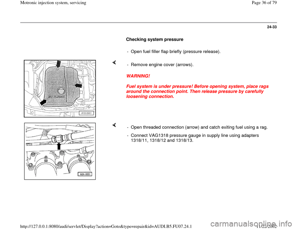
- Open fuel filler flap briefly (pressure release).
WARNING!
Fuel system is under pressure! Before opening system, place rags
around the connection point. Then release pressure by carefully
loosening connection. - Remove engine cover (arrows).
- Open threaded connection (arrow) and catch exiting fuel using a rag.
- Connect VAG1318 pressure gauge in supply line using adapters
1318/11, 1318/12 and 1318/13.
Pa
ge 36 of 79 Motronic in
jection s
ystem, servicin
g
11/22/2002 htt
p://127.0.0.1:8080/audi/servlet/Dis
play?action=Goto&t
yp
e=re
pair&id=AUDI.B5.FU07.24.1
Page 50 of 79
24-46
- Disconnect fuel distributor with injectors from
intake plenum and set aside in rear of engine
compartment on a clean cloth.
WARNING!
Fuel system is under pressure! Before
opening system, place rags around the
connection point. Then release pressure by
carefully loosening connection.
- Disengage retaining clip and remove fuel
injector.
Note:
Fuel lines must be removed before replacing fuel
distributor.
Installation is reverse of removal, noting the
following:
Remove O-rings at all opened connections.
(Never remove plastic cap from valve head
ro replace front O-ring - pry O-ring off over
plastic cap).
Lightly lubricate O-rings with clean engine
oil.
Pa
ge 50 of 79 Motronic in
jection s
ystem, servicin
g
11/22/2002 htt
p://127.0.0.1:8080/audi/servlet/Dis
play?action=Goto&t
yp
e=re
pair&id=AUDI.B5.FU07.24.1