lock AUDI A4 2000 B5 / 1.G Brakes Basic Setting 04 Owner's Manual
[x] Cancel search | Manufacturer: AUDI, Model Year: 2000, Model line: A4, Model: AUDI A4 2000 B5 / 1.GPages: 64, PDF Size: 0.31 MB
Page 38 of 64

01-275
Note:
The display group numbers can be selected in
sequence by pressing buttons <-1 and 3-> on the
VAG1551 scan tool, or the arrow buttons and
on the VAG1552 mobile scan tool or the arrow
buttons and on the screen of the VAS5051
tester.
- Press -C- button to input display group number
manually. Read measurin
g value block
Enter display group number XXX
Indicated on display:
- Press buttons 1-, 2- and -5-.
- Press -Q- button to confirm input.
Pa
ge 38 of 64 Basic settin
g (scan tool function 04
)
11/20/2002 htt
p://127.0.0.1:8080/audi/servlet/Dis
play?action=Goto&t
yp
e=re
pair&id=AUDI.B5.SU02.01.15
Page 40 of 64
01-277
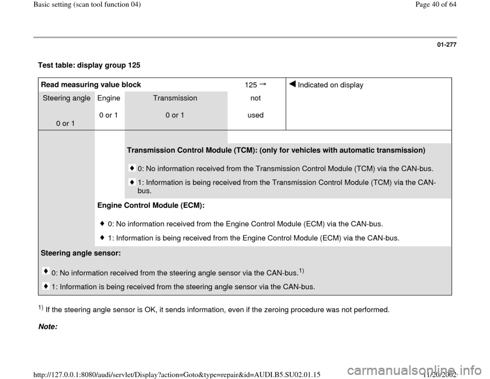
Test table: display group 125 Read measuring value block
125
Indicated on display
Steering angle
0 or 1 Engine
0 or 1
Transmission
0 or 1 not
used
Transmission Control Module (TCM): (only for vehicles with automatic transmission)
0: No information received from the Transmission Control Module (TCM) via the CAN-bus.
1: Information is being received from the Transmission Control Module (TCM) via the CAN-
bus.
Engine Control Module (ECM):
0: No information received from the Engine Control Module (ECM) via the CAN-bus.
1: Information is being received from the Engine Control Module (ECM) via the CAN-bus.
Steering angle sensor:
0: No information received from the steering angle sensor via the CAN-bus.
1)
1: Information is being received from the steering angle sensor via the CAN-bus.
1) If the steering angle sensor is OK, it sends information, even if the zeroing procedure was not performed.
Note:
Pa
ge 40 of 64 Basic settin
g (scan tool function 04
)
11/20/2002 htt
p://127.0.0.1:8080/audi/servlet/Dis
play?action=Goto&t
yp
e=re
pair&id=AUDI.B5.SU02.01.15
Page 46 of 64
01-282
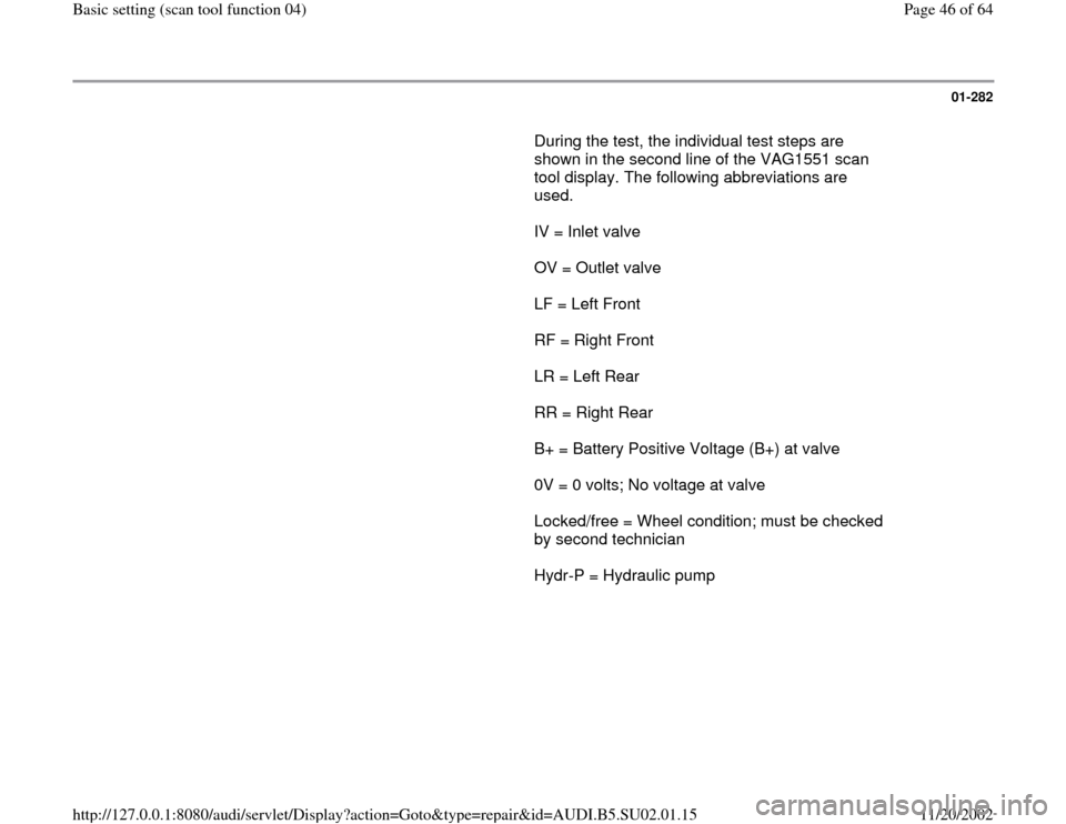
During the test, the individual test steps are
shown in the second line of the VAG1551 scan
tool display. The following abbreviations are
used.
IV = Inlet valve
OV = Outlet valve
LF = Left Front
RF = Right Front
LR = Left Rear
RR = Right Rear
B+ = Battery Positive Voltage (B+) at valve
0V = 0 volts; No voltage at valve
Locked/free = Wheel condition; must be checked
by second technician
Hydr-P = Hydraulic pump
Pa
ge 46 of 64 Basic settin
g (scan tool function 04
)
11/20/2002 htt
p://127.0.0.1:8080/audi/servlet/Dis
play?action=Goto&t
yp
e=re
pair&id=AUDI.B5.SU02.01.15
Page 48 of 64
01-284
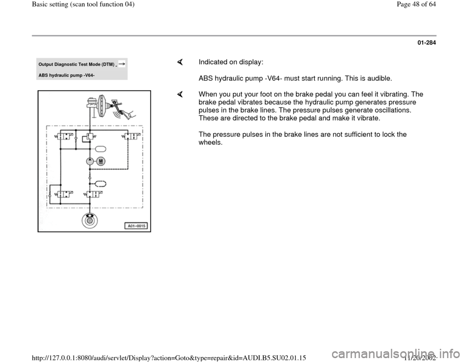
Output Diagnostic Test Mode (DTM)
-
ABS hydraulic pump -
V64-
Indicated on display:
ABS hydraulic pump -V64- must start running. This is audible.
When you put your foot on the brake pedal you can feel it vibrating. The
brake pedal vibrates because the hydraulic pump generates pressure
pulses in the brake lines. The pressure pulses generate oscillations.
These are directed to the brake pedal and make it vibrate.
The pressure pulses in the brake lines are not sufficient to lock the
wheels.
Pa
ge 48 of 64 Basic settin
g (scan tool function 04
)
11/20/2002 htt
p://127.0.0.1:8080/audi/servlet/Dis
play?action=Goto&t
yp
e=re
pair&id=AUDI.B5.SU02.01.15
Page 50 of 64
01-286
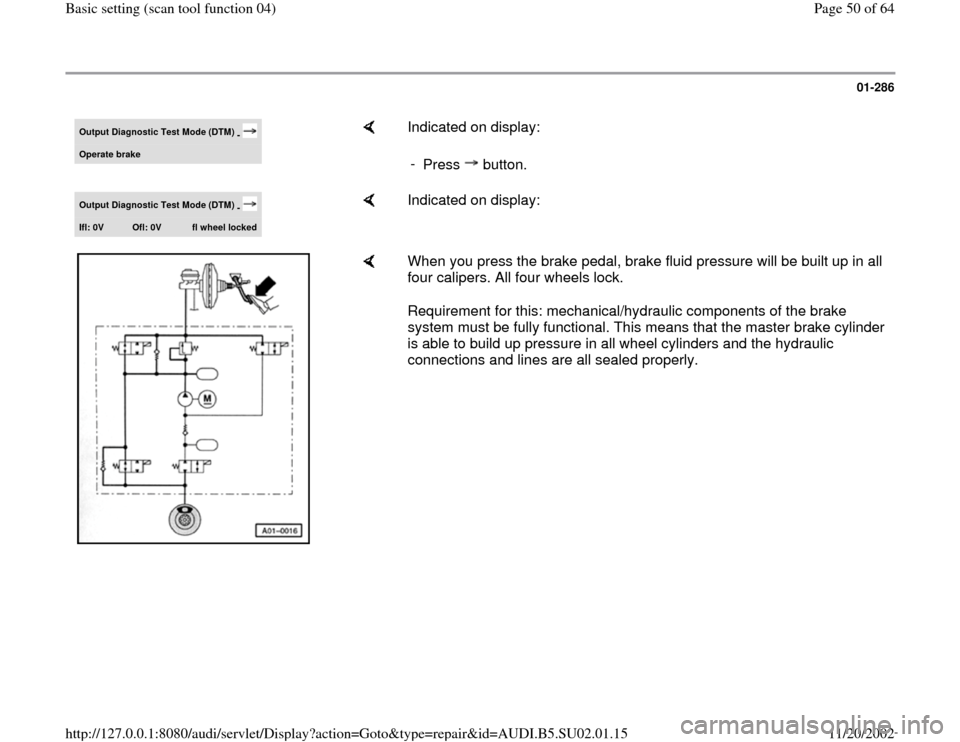
Output Diagnostic Test Mode (DTM)
-
Operate brake
Indicated on display:
-
Press button.
Output Diagnostic Test Mode (DTM)
-
Ifl: 0V
Ofl: 0V
fl wheel locked
Indicated on display:
When you press the brake pedal, brake fluid pressure will be built up in all
four calipers. All four wheels lock.
Requirement for this: mechanical/hydraulic components of the brake
system must be fully functional. This means that the master brake cylinder
is able to build up pressure in all wheel cylinders and the hydraulic
connections and lines are all sealed properly.
Pa
ge 50 of 64 Basic settin
g (scan tool function 04
)
11/20/2002 htt
p://127.0.0.1:8080/audi/servlet/Dis
play?action=Goto&t
yp
e=re
pair&id=AUDI.B5.SU02.01.15
Page 51 of 64
01-287
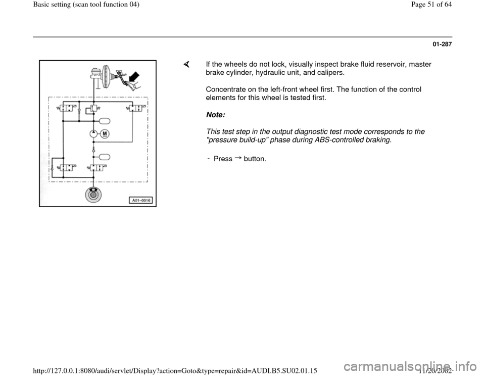
If the wheels do not lock, visually inspect brake fluid reservoir, master
brake cylinder, hydraulic unit, and calipers.
Concentrate on the left-front wheel first. The function of the control
elements for this wheel is tested first.
Note:
This test step in the output diagnostic test mode corresponds to the
"pressure build-up" phase during ABS-controlled braking.
-
Press button.
Pa
ge 51 of 64 Basic settin
g (scan tool function 04
)
11/20/2002 htt
p://127.0.0.1:8080/audi/servlet/Dis
play?action=Goto&t
yp
e=re
pair&id=AUDI.B5.SU02.01.15
Page 52 of 64
01-288
Output Diagnostic Test Mode (DTM)
-
Ifl: B+
Ofl: 0V
fl wheel locked
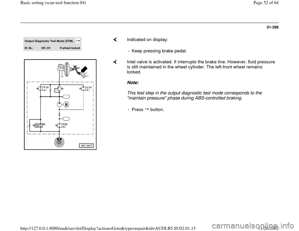
Indicated on display:
- Keep pressing brake pedal.
Inlet valve is activated. It interrupts the brake line. However, fluid pressure
is still maintained in the wheel cylinder. The left-front wheel remains
locked.
Note:
This test step in the output diagnostic test mode corresponds to the
"maintain pressure" phase during ABS-controlled braking.
-
Press button.
Pa
ge 52 of 64 Basic settin
g (scan tool function 04
)
11/20/2002 htt
p://127.0.0.1:8080/audi/servlet/Dis
play?action=Goto&t
yp
e=re
pair&id=AUDI.B5.SU02.01.15
Page 56 of 64
01-292
Output Diagnostic Test Mode (DTM)
-
Ifl: 0V
Ofl: 0V
fl wheel locked
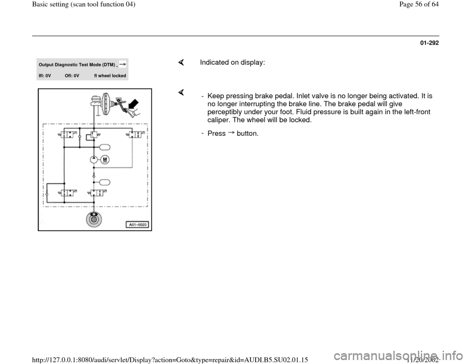
Indicated on display:
- Keep pressing brake pedal. Inlet valve is no longer being activated. It is
no longer interrupting the brake line. The brake pedal will give
perceptibly under your foot. Fluid pressure is built again in the left-front
caliper. The wheel will be locked.
-
Press button.
Pa
ge 56 of 64 Basic settin
g (scan tool function 04
)
11/20/2002 htt
p://127.0.0.1:8080/audi/servlet/Dis
play?action=Goto&t
yp
e=re
pair&id=AUDI.B5.SU02.01.15
Page 58 of 64

01-294
Output Diagnostic Test Mode (DTM)
-
Operate brake
Indicated on display:
-
Press button.
Output Diagnostic Test Mode (DTM)
-
Ifr: 0V
Ofr: 0V
fr wheel locked
Indicated on display:
-
Press button.
Output Diagnostic Test Mode (DTM)
-
Ifr: B+
Ofr: 0V
fr wheel locked
Indicated on display:
ABS hydraulic pump -V64- must start running.
The brake pedal must not give. -
Press button.
Output Diagnostic Test Mode (DTM)
-
Ifr: B+
Ofr: B+
fr wheel free
Indicated on display:
ABS hydraulic pump -V64- will stop running. -
Press button.
Pa
ge 58 of 64 Basic settin
g (scan tool function 04
)
11/20/2002 htt
p://127.0.0.1:8080/audi/servlet/Dis
play?action=Goto&t
yp
e=re
pair&id=AUDI.B5.SU02.01.15
Page 59 of 64

01-295
Output Diagnostic Test Mode (DTM)
-
Ifr: B+
Ofr: 0V
fr wheel free
Indicated on display:
Brake pedal must give noticeably. -
Press button.
Output Diagnostic Test Mode (DTM)
-
Ifr: 0V
Ofr: 0V
fr wheel locked
Indicated on display:
-
Press button.
Output Diagnostic Test Mode (DTM)
-
Release brake
Indicated on display:
-
Press button.
Output Diagnostic Test Mode (DTM)
-
Operate brake
Indicated on display:
-
Press button.
Output Diagnostic Test Mode (DTM)
-
Irl 0V
Orl: 0V
rl wheel locked
Indicated on display:
-
Press button.
Pa
ge 59 of 64 Basic settin
g (scan tool function 04
)
11/20/2002 htt
p://127.0.0.1:8080/audi/servlet/Dis
play?action=Goto&t
yp
e=re
pair&id=AUDI.B5.SU02.01.15