engine AUDI A4 2000 B5 / 1.G Instrument Cluster Location Diagram Through Model Year 2000 Workshop Manual
[x] Cancel search | Manufacturer: AUDI, Model Year: 2000, Model line: A4, Model: AUDI A4 2000 B5 / 1.GPages: 28, PDF Size: 0.15 MB
Page 1 of 28
90-25
Instrument cluster (from M.Y.
2000)
WARNING!
Disconnect battery Ground (GND) cable
before performing work on the electrical
system.
Notes:
Obtain radio code before disconnecting
battery.
Be sure to activate vehicle features (radio,
clock, electric window regulator, engine)
according to owner's manual when the battery
is re-connected.
Pa
ge 1 of 28 Instrument cluster
(from M.Y. 2000
)
11/20/2002 htt
p://127.0.0.1:8080/audi/servlet/Dis
play?action=Goto&t
yp
e=re
pair&id=AUDI.B5.EE01.90.2
Page 11 of 28
90-35
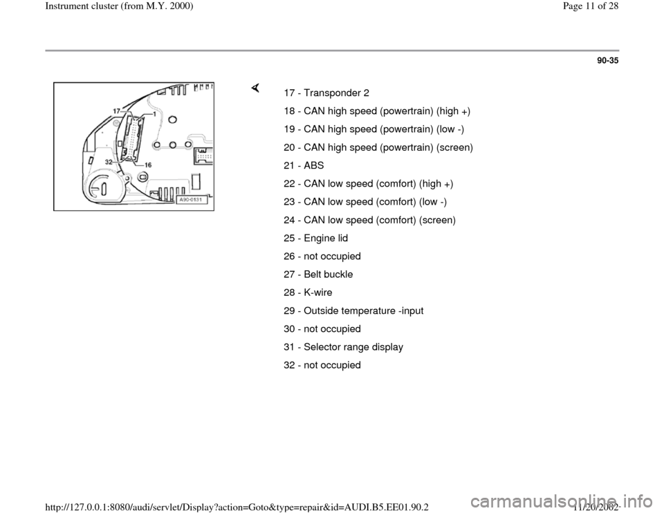
17 - Transponder 2
18 - CAN high speed (powertrain) (high +)
19 - CAN high speed (powertrain) (low -)
20 - CAN high speed (powertrain) (screen)
21 - ABS
22 - CAN low speed (comfort) (high +)
23 - CAN low speed (comfort) (low -)
24 - CAN low speed (comfort) (screen)
25 - Engine lid
26 - not occupied
27 - Belt buckle
28 - K-wire
29 - Outside temperature -input
30 - not occupied
31 - Selector range display
32 - not occupied
Pa
ge 11 of 28 Instrument cluster
(from M.Y. 2000
)
11/20/2002 htt
p://127.0.0.1:8080/audi/servlet/Dis
play?action=Goto&t
yp
e=re
pair&id=AUDI.B5.EE01.90.2
Page 14 of 28
90-38
Engine speed signal, checking
If a malfunction of the RPM display at tachometer
is detected, signal at the tachometer must be
checked.
- Connect VAS5051 tester or VAG1551 scan tool
Page 01
-241
.
- Read Measuring Value Block Page 01
-
114
.
- Select display group number 001 and perform a
road test.
If the speed appears on the VAG1551 Scan Tool
display but not via the speedometer in instrument
cluster, the instrument cluster is faulty and must
be replaced.
If no speed is indicated on the VAG1551 Scan
Tool display either, the signal must be checked
at multi-function connection at instrument
cluster.
- Remove instrument cluster Page 90
-27
.
Pa
ge 14 of 28 Instrument cluster
(from M.Y. 2000
)
11/20/2002 htt
p://127.0.0.1:8080/audi/servlet/Dis
play?action=Goto&t
yp
e=re
pair&id=AUDI.B5.EE01.90.2
Page 19 of 28
90-42
Signal from Engine Coolant
Temperature (ECT) sensor -G2-,
checking
If a malfunction of the Engine Coolant
Temperature (ECT) gauge is detected at the
instrument cluster, check if the signal at the
instrument cluster is OK.
- Connect VAS5051 tester or VAG1551 scan tool
Page 01
-241
.
- Read Measuring Value Block Page 01
-
114
.
- Select display group number 003.
If the Engine Coolant Temperature (ECT)
appears on the VAG1551 scan tool display but
not by the Engine Coolant Temperature (ECT)
gauge, the instrument cluster is faulty and must
be replaced.
If no Engine Coolant Temperature (ECT) is
indicated on the VAG1551 scan tool display, the
signal must be checked at multi-function
connection at instrument cluster.
- Remove instrument cluster Page 90
-27
.
Pa
ge 19 of 28 Instrument cluster
(from M.Y. 2000
)
11/20/2002 htt
p://127.0.0.1:8080/audi/servlet/Dis
play?action=Goto&t
yp
e=re
pair&id=AUDI.B5.EE01.90.2
Page 21 of 28
90-43
- Measure resistance (sensor resistance) between
terminal 8 and 7 using VAG1526 multimeter.
Specified values:
Coolant temperature 90 C: approx. 110 Ohm
Coolant temperature 120 C: approx. 50 Ohm If the specified values are not reached, the wire
connection to Engine Coolant Temperature
(ECT) -G2- must be checked.
- Check wire connection according to wiring
diagram.
Electrical Wiring Diagrams, Troubleshooting &
Component Locations If the wire connection is OK, Engine Coolant
Temperature (ECT) -G2- must be replaced.
Pa
ge 21 of 28 Instrument cluster
(from M.Y. 2000
)
11/20/2002 htt
p://127.0.0.1:8080/audi/servlet/Dis
play?action=Goto&t
yp
e=re
pair&id=AUDI.B5.EE01.90.2
Page 22 of 28
90-44
Consumption signal, checking
Special tools and equipment
VAG1526 multimeter
VAG1598 test box with VAG1598/25 adapter
VAG1594 connector test kit
Test box for the individual Engine Control
Module (ECM)
- Set display indicator of board computer to
current consumption (1/100 km),
- Start engine and perform a road test.
- Observe consumption display in instrument
cluster.
Pa
ge 22 of 28 Instrument cluster
(from M.Y. 2000
)
11/20/2002 htt
p://127.0.0.1:8080/audi/servlet/Dis
play?action=Goto&t
yp
e=re
pair&id=AUDI.B5.EE01.90.2
Page 23 of 28
90-45
What appears in the consumption display?
1. constant 0.0 L/100 km
Possible short circuit to battery Ground (GND)
in the signal wire.
- Switch ignition off.
- Connect corresponding test box to the Engine
Control Module (ECM).
Repair Manual, Fuel Injection & Ignition,
Repair Group 24; additional signals, checking;
consumption signal for board computer, checking
- Remove instrument cluster Page 90
-27
and
disconnect blue 32-pin connector from
instrument cluster.
- Connect VAG1598 tester with VAG1598/25
adapter to the blue 32-pin connector.
- Connect (+) adapter lead to VAG1598/25 test
box socket 25 using VAG1526 multimeter
Pa
ge 23 of 28 Instrument cluster
(from M.Y. 2000
)
11/20/2002 htt
p://127.0.0.1:8080/audi/servlet/Dis
play?action=Goto&t
yp
e=re
pair&id=AUDI.B5.EE01.90.2
Page 24 of 28
- Connect (-) adapter lead to the corresponding
test box of Engine Control Module (ECM) and
the corresponding consumption signal socket of
the Engine Control Module (ECM).
Pa
ge 24 of 28 Instrument cluster
(from M.Y. 2000
)
11/20/2002 htt
p://127.0.0.1:8080/audi/servlet/Dis
play?action=Goto&t
yp
e=re
pair&id=AUDI.B5.EE01.90.2
Page 25 of 28
90-46
- Perform a resistance check.
Specification: Display < 2 Ohm
- Connect (+) adapter lead to to the corresponding
test box of the Engine Control Module (ECM)
using VAG1526 multimeter
- Connect (-) adapter lead to battery Ground
(GND).
- Perform a resistance check.
Specification: Display > 9 M Ohm
- If the specified values are reached, the wire
connection is OK.
Pa
ge 25 of 28 Instrument cluster
(from M.Y. 2000
)
11/20/2002 htt
p://127.0.0.1:8080/audi/servlet/Dis
play?action=Goto&t
yp
e=re
pair&id=AUDI.B5.EE01.90.2
Page 26 of 28
90-47
2. constant 51 L/100 km
Possible open circuit in the signal wire.
- Switch ignition off.
- Connect test box to Engine Control Module
(ECM).
Repair Manual, Fuel Injection & Ignition,
Repair Group 24; additional signals, checking;
consumption signal for board computer, checking
- Remove instrument cluster Page 90
-27
and
disconnect blue 32-pin connector from
instrument cluster.
- Connect VAG1598 tester with VAG1598/25
adapter to the blue 32-pin connector.
- Connect (+) adapter lead to VAG1598/25 test
box socket 25 using VAG1526 multimeter.
-
Connect (-) adapter lead to the corresponding
test box of Engine Control Module (ECM) and
the corresponding consumption signal socket of
Pa
ge 26 of 28 Instrument cluster
(from M.Y. 2000
)
11/20/2002 htt
p://127.0.0.1:8080/audi/servlet/Dis
play?action=Goto&t
yp
e=re
pair&id=AUDI.B5.EE01.90.2