ESP AUDI A4 2000 B5 / 1.G Instrument Cluster Location Diagram Through Model Year 2000 Workshop Manual
[x] Cancel search | Manufacturer: AUDI, Model Year: 2000, Model line: A4, Model: AUDI A4 2000 B5 / 1.GPages: 28, PDF Size: 0.15 MB
Page 9 of 28
90-33
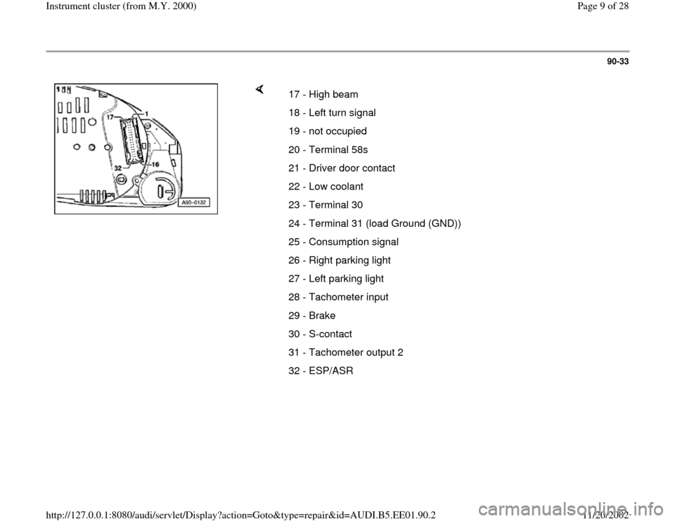
17 - High beam
18 - Left turn signal
19 - not occupied
20 - Terminal 58s
21 - Driver door contact
22 - Low coolant
23 - Terminal 30
24 - Terminal 31 (load Ground (GND))
25 - Consumption signal
26 - Right parking light
27 - Left parking light
28 - Tachometer input
29 - Brake
30 - S-contact
31 - Tachometer output 2
32 - ESP/ASR
Pa
ge 9 of 28 Instrument cluster
(from M.Y. 2000
)
11/20/2002 htt
p://127.0.0.1:8080/audi/servlet/Dis
play?action=Goto&t
yp
e=re
pair&id=AUDI.B5.EE01.90.2
Page 23 of 28
90-45
What appears in the consumption display?
1. constant 0.0 L/100 km
Possible short circuit to battery Ground (GND)
in the signal wire.
- Switch ignition off.
- Connect corresponding test box to the Engine
Control Module (ECM).
Repair Manual, Fuel Injection & Ignition,
Repair Group 24; additional signals, checking;
consumption signal for board computer, checking
- Remove instrument cluster Page 90
-27
and
disconnect blue 32-pin connector from
instrument cluster.
- Connect VAG1598 tester with VAG1598/25
adapter to the blue 32-pin connector.
- Connect (+) adapter lead to VAG1598/25 test
box socket 25 using VAG1526 multimeter
Pa
ge 23 of 28 Instrument cluster
(from M.Y. 2000
)
11/20/2002 htt
p://127.0.0.1:8080/audi/servlet/Dis
play?action=Goto&t
yp
e=re
pair&id=AUDI.B5.EE01.90.2
Page 24 of 28
- Connect (-) adapter lead to the corresponding
test box of Engine Control Module (ECM) and
the corresponding consumption signal socket of
the Engine Control Module (ECM).
Pa
ge 24 of 28 Instrument cluster
(from M.Y. 2000
)
11/20/2002 htt
p://127.0.0.1:8080/audi/servlet/Dis
play?action=Goto&t
yp
e=re
pair&id=AUDI.B5.EE01.90.2
Page 25 of 28
90-46
- Perform a resistance check.
Specification: Display < 2 Ohm
- Connect (+) adapter lead to to the corresponding
test box of the Engine Control Module (ECM)
using VAG1526 multimeter
- Connect (-) adapter lead to battery Ground
(GND).
- Perform a resistance check.
Specification: Display > 9 M Ohm
- If the specified values are reached, the wire
connection is OK.
Pa
ge 25 of 28 Instrument cluster
(from M.Y. 2000
)
11/20/2002 htt
p://127.0.0.1:8080/audi/servlet/Dis
play?action=Goto&t
yp
e=re
pair&id=AUDI.B5.EE01.90.2
Page 26 of 28
90-47
2. constant 51 L/100 km
Possible open circuit in the signal wire.
- Switch ignition off.
- Connect test box to Engine Control Module
(ECM).
Repair Manual, Fuel Injection & Ignition,
Repair Group 24; additional signals, checking;
consumption signal for board computer, checking
- Remove instrument cluster Page 90
-27
and
disconnect blue 32-pin connector from
instrument cluster.
- Connect VAG1598 tester with VAG1598/25
adapter to the blue 32-pin connector.
- Connect (+) adapter lead to VAG1598/25 test
box socket 25 using VAG1526 multimeter.
-
Connect (-) adapter lead to the corresponding
test box of Engine Control Module (ECM) and
the corresponding consumption signal socket of
Pa
ge 26 of 28 Instrument cluster
(from M.Y. 2000
)
11/20/2002 htt
p://127.0.0.1:8080/audi/servlet/Dis
play?action=Goto&t
yp
e=re
pair&id=AUDI.B5.EE01.90.2
Page 28 of 28
90-48
- Connect (+) adapter lead to to the corresponding
test box of the Engine Control Module (ECM)
using VAG1526 multimeter
- Connect (-) adapter lead to battery Ground
(GND).
- Perform a resistance check.
Specification: Display > 9 M Ohm
- If the specified values are reached, the wire
connection is OK.
3. The consumption display has no logical or
fluctuating consumption value.
The consumption display deviates from the
actual fuel consumption.
- Perform adaptation of consumption display
Page 01
-140
.
Pa
ge 28 of 28 Instrument cluster
(from M.Y. 2000
)
11/20/2002 htt
p://127.0.0.1:8080/audi/servlet/Dis
play?action=Goto&t
yp
e=re
pair&id=AUDI.B5.EE01.90.2