ad blue AUDI A4 2000 B5 / 1.G Instrument Cluster Location Diagram Through Model Year 2000 Workshop Manual
[x] Cancel search | Manufacturer: AUDI, Model Year: 2000, Model line: A4, Model: AUDI A4 2000 B5 / 1.GPages: 28, PDF Size: 0.15 MB
Page 6 of 28
90-30
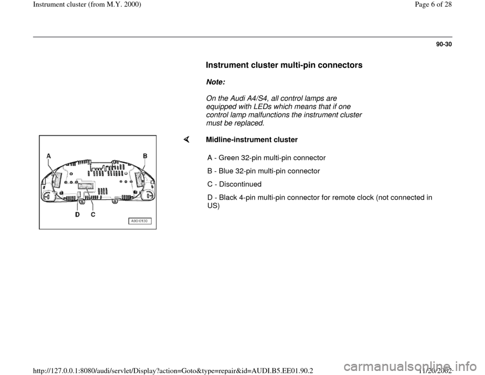
Instrument cluster multi-pin connectors
Note:
On the Audi A4/S4, all control lamps are
equipped with LEDs which means that if one
control lamp malfunctions the instrument cluster
must be replaced.
Midline-instrument cluster
A - Green 32-pin multi-pin connector
B - Blue 32-pin multi-pin connector
C - Discontinued
D - Black 4-pin multi-pin connector for remote clock (not connected in
US)
Pa
ge 6 of 28 Instrument cluster
(from M.Y. 2000
)
11/20/2002 htt
p://127.0.0.1:8080/audi/servlet/Dis
play?action=Goto&t
yp
e=re
pair&id=AUDI.B5.EE01.90.2
Page 7 of 28
90-31
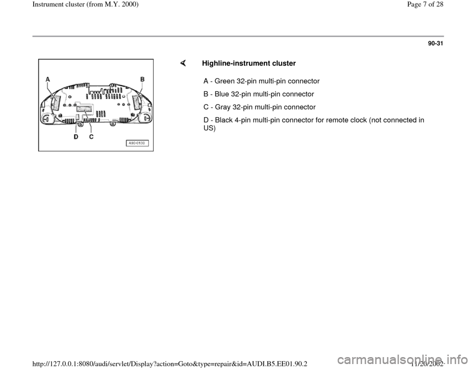
Highline-instrument cluster
A - Green 32-pin multi-pin connector
B - Blue 32-pin multi-pin connector
C - Gray 32-pin multi-pin connector
D - Black 4-pin multi-pin connector for remote clock (not connected in
US)
Pa
ge 7 of 28 Instrument cluster
(from M.Y. 2000
)
11/20/2002 htt
p://127.0.0.1:8080/audi/servlet/Dis
play?action=Goto&t
yp
e=re
pair&id=AUDI.B5.EE01.90.2
Page 8 of 28
90-32
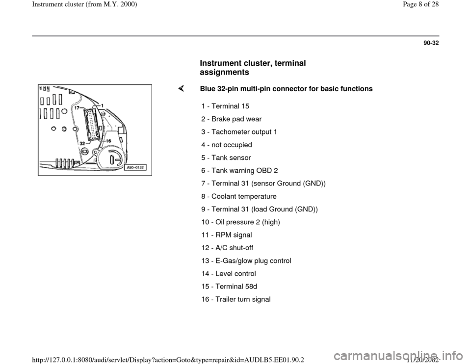
Instrument cluster, terminal
assignments
Blue 32-pin multi-pin connector for basic functions
1 - Terminal 15
2 - Brake pad wear
3 - Tachometer output 1
4 - not occupied
5 - Tank sensor
6 - Tank warning OBD 2
7 - Terminal 31 (sensor Ground (GND))
8 - Coolant temperature
9 - Terminal 31 (load Ground (GND))
10 - Oil pressure 2 (high)
11 - RPM signal
12 - A/C shut-off
13 - E-Gas/glow plug control
14 - Level control
15 - Terminal 58d
16 - Trailer turn signal
Pa
ge 8 of 28 Instrument cluster
(from M.Y. 2000
)
11/20/2002 htt
p://127.0.0.1:8080/audi/servlet/Dis
play?action=Goto&t
yp
e=re
pair&id=AUDI.B5.EE01.90.2
Page 15 of 28
90-39
- Connect VAG1598 tester with VAG1598/25
adapter to the blue 32-pin connector.
- Perform an acoustic continuity check of the
sensor and wire using the VAG1526 multimeter
between terminal 28 and socket 9 (load Ground
(GND))
Test
The beep signal of the resistance tester must
switch on and off several times while the vehicle
is rolled slightly forward and backward (approx.
1m)
If the test is not OK, the wire connection to speed
sender must be checked.
- Check wire connection according to wiring
diagram.
Electrical Wiring Diagrams, Troubleshooting &
Component Locations If the wire connection is OK, the speed sender
must be replaced.
Pa
ge 15 of 28 Instrument cluster
(from M.Y. 2000
)
11/20/2002 htt
p://127.0.0.1:8080/audi/servlet/Dis
play?action=Goto&t
yp
e=re
pair&id=AUDI.B5.EE01.90.2
Page 16 of 28
90-40
Signal from sender for fuel gauge -G-,
checking
If a malfunction of the sender for fuel gauge is
detected at instrument cluster, check if the signal
at the instrument cluster is OK.
- Connect VAS5051 tester or VAG1551 scan tool
Page 01
-241
.
- Read Measuring Value Block Page 01
-
114
.
- Select display group number 2.
If the fuel level appears on the VAG1551 scan
tool display but not via the fuel gauge, the
instrument cluster is faulty and must be
replaced.
If no speed is indicated on the VAG1551 scan
tool display either, the signal must be checked at
multi-function connection at instrument cluster.
- Remove instrument cluster Page 90
-27
.
- Connect VAG1598 tester with VAG1598/25
adapter to the blue 32-pin connector.
Pa
ge 16 of 28 Instrument cluster
(from M.Y. 2000
)
11/20/2002 htt
p://127.0.0.1:8080/audi/servlet/Dis
play?action=Goto&t
yp
e=re
pair&id=AUDI.B5.EE01.90.2
Page 20 of 28
- Connect VAG1598 tester with VAG1598/25
adapter to the blue 32-pin connector.
Pa
ge 20 of 28 Instrument cluster
(from M.Y. 2000
)
11/20/2002 htt
p://127.0.0.1:8080/audi/servlet/Dis
play?action=Goto&t
yp
e=re
pair&id=AUDI.B5.EE01.90.2
Page 23 of 28
90-45
What appears in the consumption display?
1. constant 0.0 L/100 km
Possible short circuit to battery Ground (GND)
in the signal wire.
- Switch ignition off.
- Connect corresponding test box to the Engine
Control Module (ECM).
Repair Manual, Fuel Injection & Ignition,
Repair Group 24; additional signals, checking;
consumption signal for board computer, checking
- Remove instrument cluster Page 90
-27
and
disconnect blue 32-pin connector from
instrument cluster.
- Connect VAG1598 tester with VAG1598/25
adapter to the blue 32-pin connector.
- Connect (+) adapter lead to VAG1598/25 test
box socket 25 using VAG1526 multimeter
Pa
ge 23 of 28 Instrument cluster
(from M.Y. 2000
)
11/20/2002 htt
p://127.0.0.1:8080/audi/servlet/Dis
play?action=Goto&t
yp
e=re
pair&id=AUDI.B5.EE01.90.2
Page 26 of 28
90-47
2. constant 51 L/100 km
Possible open circuit in the signal wire.
- Switch ignition off.
- Connect test box to Engine Control Module
(ECM).
Repair Manual, Fuel Injection & Ignition,
Repair Group 24; additional signals, checking;
consumption signal for board computer, checking
- Remove instrument cluster Page 90
-27
and
disconnect blue 32-pin connector from
instrument cluster.
- Connect VAG1598 tester with VAG1598/25
adapter to the blue 32-pin connector.
- Connect (+) adapter lead to VAG1598/25 test
box socket 25 using VAG1526 multimeter.
-
Connect (-) adapter lead to the corresponding
test box of Engine Control Module (ECM) and
the corresponding consumption signal socket of
Pa
ge 26 of 28 Instrument cluster
(from M.Y. 2000
)
11/20/2002 htt
p://127.0.0.1:8080/audi/servlet/Dis
play?action=Goto&t
yp
e=re
pair&id=AUDI.B5.EE01.90.2