ECU AUDI A4 2001 B5 / 1.G 01V Transmission Select Lever Mechanism Workshop Manual
[x] Cancel search | Manufacturer: AUDI, Model Year: 2001, Model line: A4, Model: AUDI A4 2001 B5 / 1.GPages: 75, PDF Size: 0.76 MB
Page 10 of 75
37-8
from top:
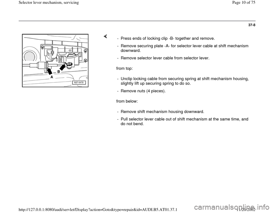
from below: - Press ends of locking clip -B- together and remove.
- Remove securing plate -A- for selector lever cable at shift mechanism
downward.
- Remove selector lever cable from selector lever.
- Unclip locking cable from securing spring at shift mechanism housing,
slightly lift up securing spring to do so.
- Remove nuts (4 pieces).
- Remove shift mechanism housing downward.
- Pull selector lever cable out of shift mechanism at the same time, and
do not bend.
Pa
ge 10 of 75 Selector lever mechanism, servicin
g
11/20/2002 htt
p://127.0.0.1:8080/audi/servlet/Dis
play?action=Goto&t
yp
e=re
pair&id=AUDI.B5.AT01.37.1
Page 11 of 75
37-9
Installing
- Installation is the reverse order of removal.
In addition, the following test steps must be
performed and observed.
Selector lever and lever/shift rod in position
"P" (park lock must engage).
- Raise vehicle.
- Guide selector lever cable into shift
mechanism.
- Do not bend selector lever cable.
- Mount shift mechanism on chassis.
- Tighten nuts (4 pieces) to 10 Nm from top.
- Secure boot of selector lever cable to shift
mechanism cover.
- Installing and adjusting locking cable page 37
-49
.
Pa
ge 11 of 75 Selector lever mechanism, servicin
g
11/20/2002 htt
p://127.0.0.1:8080/audi/servlet/Dis
play?action=Goto&t
yp
e=re
pair&id=AUDI.B5.AT01.37.1
Page 12 of 75
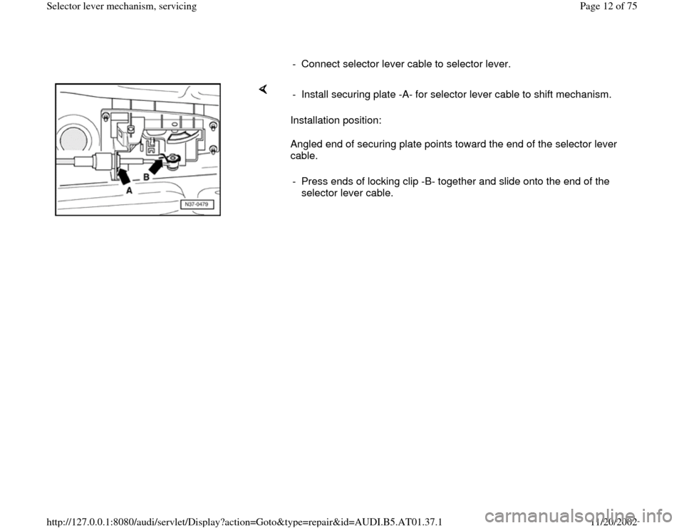
- Connect selector lever cable to selector lever.
Installation position:
Angled end of securing plate points toward the end of the selector lever
cable. - Install securing plate -A- for selector lever cable to shift mechanism.
- Press ends of locking clip -B- together and slide onto the end of the
selector lever cable.
Pa
ge 12 of 75 Selector lever mechanism, servicin
g
11/20/2002 htt
p://127.0.0.1:8080/audi/servlet/Dis
play?action=Goto&t
yp
e=re
pair&id=AUDI.B5.AT01.37.1
Page 16 of 75
37-13
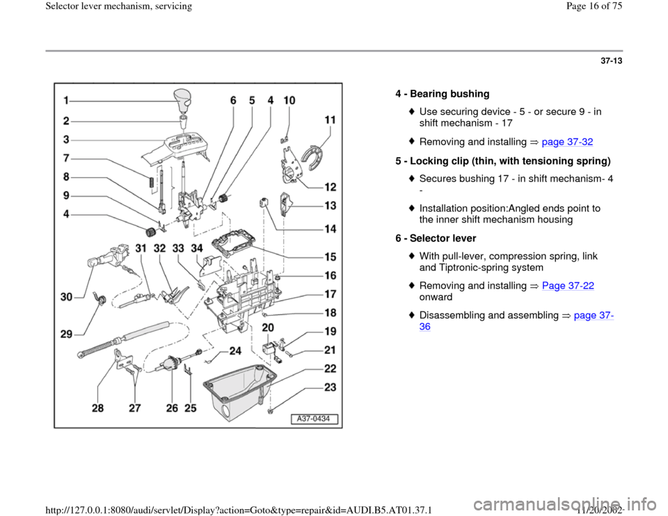
4 -
Bearing bushing
Use securing device - 5 - or secure 9 - in
shift mechanism - 17 Removing and installing page 37
-32
5 -
Locking clip (thin, with tensioning spring)
Secures bushing 17 - in shift mechanism- 4
- Installation position:Angled ends point to
the inner shift mechanism housing
6 -
Selector lever With pull-lever, compression spring, link
and Tiptronic-spring system Removing and installing Page 37
-22
onward
Disassembling and assembling page 37
-
36
Pa
ge 16 of 75 Selector lever mechanism, servicin
g
11/20/2002 htt
p://127.0.0.1:8080/audi/servlet/Dis
play?action=Goto&t
yp
e=re
pair&id=AUDI.B5.AT01.37.1
Page 17 of 75
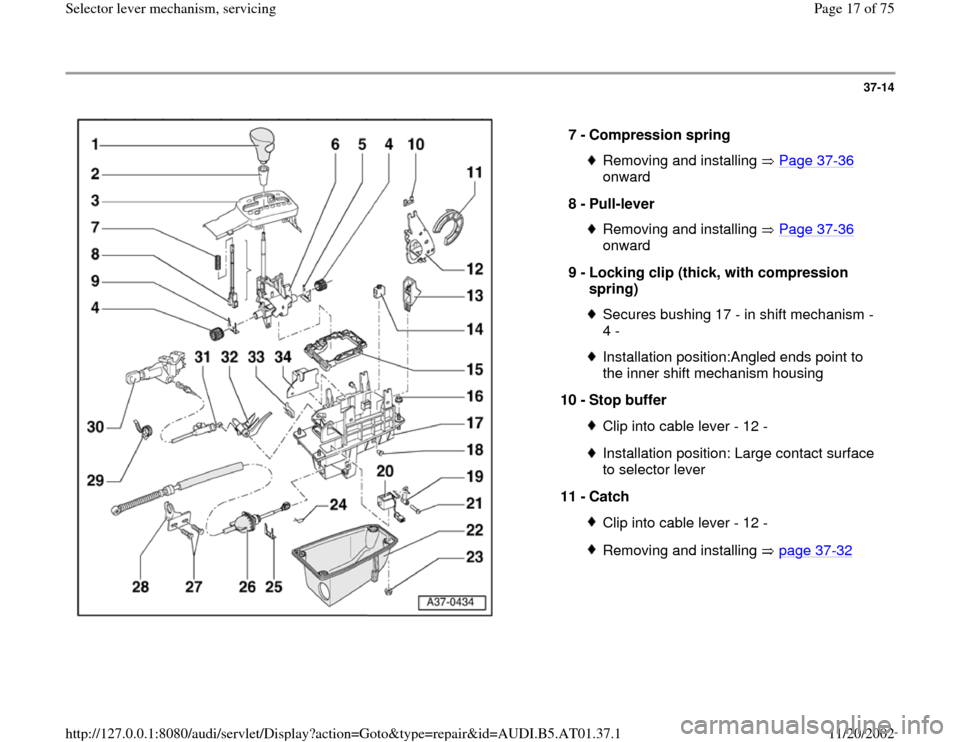
37-14
7 -
Compression spring
Removing and installing Page 37
-36
onward
8 -
Pull-lever
Removing and installing Page 37
-36
onward
9 -
Locking clip (thick, with compression
spring)
Secures bushing 17 - in shift mechanism -
4 - Installation position:Angled ends point to
the inner shift mechanism housing
10 -
Stop buffer Clip into cable lever - 12 -Installation position: Large contact surface
to selector lever
11 -
Catch Clip into cable lever - 12 -Removing and installing page 37
-32
Pa
ge 17 of 75 Selector lever mechanism, servicin
g
11/20/2002 htt
p://127.0.0.1:8080/audi/servlet/Dis
play?action=Goto&t
yp
e=re
pair&id=AUDI.B5.AT01.37.1
Page 18 of 75
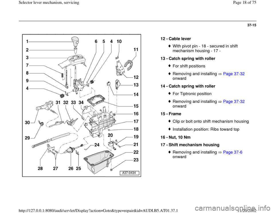
37-15
12 -
Cable lever
With pivot pin - 18 - secured in shift
mechanism housing - 17 -
13 -
Catch spring with roller For shift positionsRemoving and installing Page 37
-32
onward
14 -
Catch spring with roller
For Tiptronic positionRemoving and installing Page 37
-32
onward
15 -
Frame
Clip or bolt onto shift mechanism housingInstallation position: Ribs toward top
16 -
Nut, 10 Nm
17 -
Shift mechanism housing Removing and installing Page 37
-6
onward
Pa
ge 18 of 75 Selector lever mechanism, servicin
g
11/20/2002 htt
p://127.0.0.1:8080/audi/servlet/Dis
play?action=Goto&t
yp
e=re
pair&id=AUDI.B5.AT01.37.1
Page 19 of 75
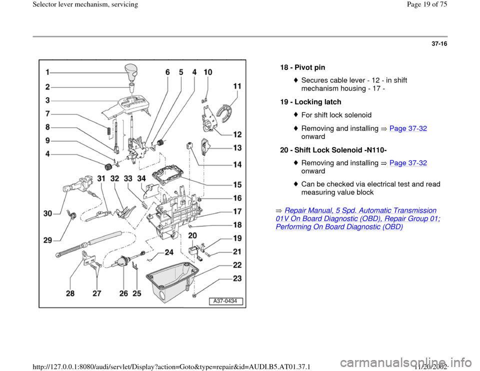
37-16
Repair Manual, 5 Spd. Automatic Transmission
01V On Board Diagnostic (OBD), Repair Group 01; Performing On Board Diagnostic (OBD)
18 -
Pivot pin
Secures cable lever - 12 - in shift
mechanism housing - 17 -
19 -
Locking latch For shift lock solenoidRemoving and installing Page 37
-32
onward
20 -
Shift Lock Solenoid -N110-
Removing and installing Page 37
-32
onward
Can be checked via electrical test and read
measuring value block
Pa
ge 19 of 75 Selector lever mechanism, servicin
g
11/20/2002 htt
p://127.0.0.1:8080/audi/servlet/Dis
play?action=Goto&t
yp
e=re
pair&id=AUDI.B5.AT01.37.1
Page 24 of 75
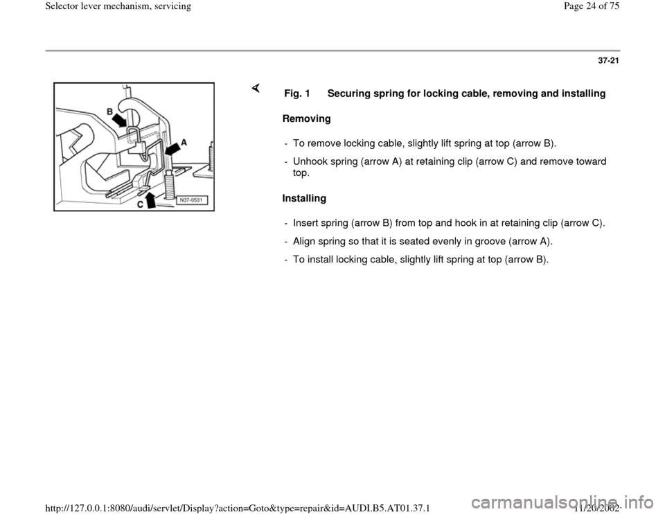
37-21
Removing
Installing Fig. 1 Securing spring for locking cable, removing and installing
- To remove locking cable, slightly lift spring at top (arrow B).
- Unhook spring (arrow A) at retaining clip (arrow C) and remove toward
top.
- Insert spring (arrow B) from top and hook in at retaining clip (arrow C).
- Align spring so that it is seated evenly in groove (arrow A).
- To install locking cable, slightly lift spring at top (arrow B).
Pa
ge 24 of 75 Selector lever mechanism, servicin
g
11/20/2002 htt
p://127.0.0.1:8080/audi/servlet/Dis
play?action=Goto&t
yp
e=re
pair&id=AUDI.B5.AT01.37.1
Page 32 of 75
37-29
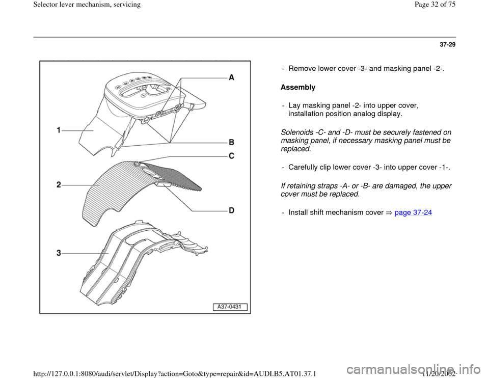
Assembly
Solenoids -C- and -D- must be securely fastened on
masking panel, if necessary masking panel must be
replaced.
If retaining straps -A- or -B- are damaged, the upper
cover must be replaced. - Remove lower cover -3- and masking panel -2-.
- Lay masking panel -2- into upper cover,
installation position analog display.
- Carefully clip lower cover -3- into upper cover -1-.
- Install shift mechanism cover page 37
-24
Pa
ge 32 of 75 Selector lever mechanism, servicin
g
11/20/2002 htt
p://127.0.0.1:8080/audi/servlet/Dis
play?action=Goto&t
yp
e=re
pair&id=AUDI.B5.AT01.37.1
Page 34 of 75
37-31
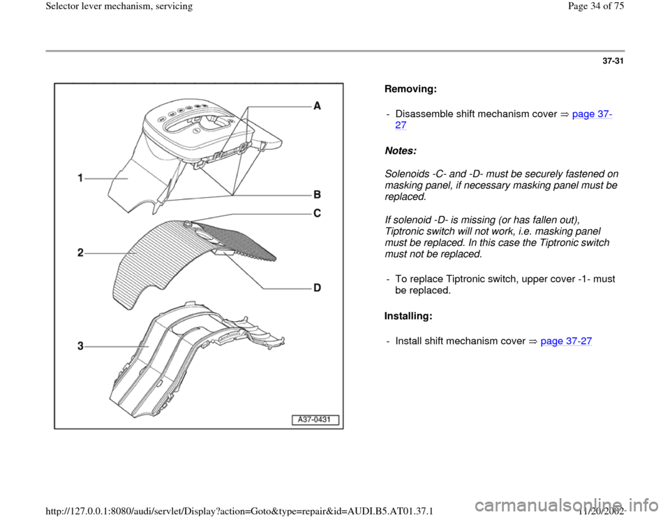
Removing:
Notes:
Solenoids -C- and -D- must be securely fastened on
masking panel, if necessary masking panel must be
replaced.
If solenoid -D- is missing (or has fallen out),
Tiptronic switch will not work, i.e. masking panel
must be replaced. In this case the Tiptronic switch
must not be replaced.
Installing: - Disassemble shift mechanism cover page 37
-
27
- To replace Tiptronic switch, upper cover -1- must
be replaced.
- Install shift mechanism cover page 37
-27
Pa
ge 34 of 75 Selector lever mechanism, servicin
g
11/20/2002 htt
p://127.0.0.1:8080/audi/servlet/Dis
play?action=Goto&t
yp
e=re
pair&id=AUDI.B5.AT01.37.1