display AUDI A4 2001 B5 / 1.G Technical Features Design And Function
[x] Cancel search | Manufacturer: AUDI, Model Year: 2001, Model line: A4, Model: AUDI A4 2001 B5 / 1.GPages: 88, PDF Size: 10.42 MB
Page 67 of 88
Downloaded from www.Manualslib.com manuals search engine
67
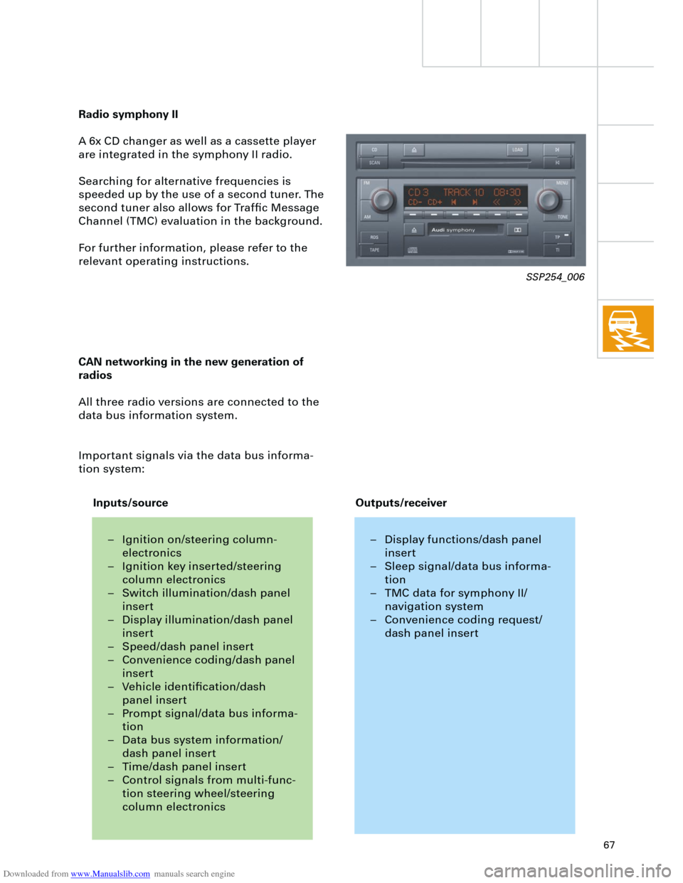
Radio symphony II
A 6x CD changer as well as a cassette player
are integrated in the symphony II radio.
Searching for alternative frequencies is
speeded up by the use of a second tuner. The
second tuner also allows for Traffic Message
Channel (TMC) evaluation in the background.
For further information, please refer to the
relevant operating instructions.
CAN networking in the new generation of
radios
All three radio versions are connected to the
data bus information system.
Important signals via the data bus informa-
tion system:
SSP254_006
– Ignition on/steering column-
electronics
– Ignition key inserted/steering
column electronics
– Switch illumination/dash panel
insert
– Display illumination/dash panel
insert
– Speed/dash panel insert
– Convenience coding/dash panel
insert
– Vehicle identification/dash
panel insert
– Prompt signal/data bus informa-
tion
– Data bus system information/
dash panel insert
– Time/dash panel insert
– Control signals from multi-func-
tion steering wheel/steering
column electronics– Display functions/dash panel
insert
– Sleep signal/data bus informa-
tion
– TMC data for symphony II/
navigation system
– Convenience coding request/
dash panel insert
Inputs/sourceOutputs/receiver
Page 68 of 88
Downloaded from www.Manualslib.com manuals search engine
68
Example:
If the radio is switched on with the ignition
key (S-contact) this requires the exchange of
data between three control units:
– Steering column electronics,
– dash panel insert (gateway) and
– radio.
If the radio does not switch on,
– the signal input in the steering column
electronics (terminal 86S),
– communication between the steering col-
umn electronics and the dash panel
(convenience data bus) and
– communication between the dash panel
and the radio
(data bus information system)
must be checked.
Diagnostics
For diagnosis of radio systems concert II and
symphony II, current consumption of aerial
diversity is monitored via the intermittent
frequency (IF) wiring.
Test mode
The new radio versions are equipped with a
test mode.
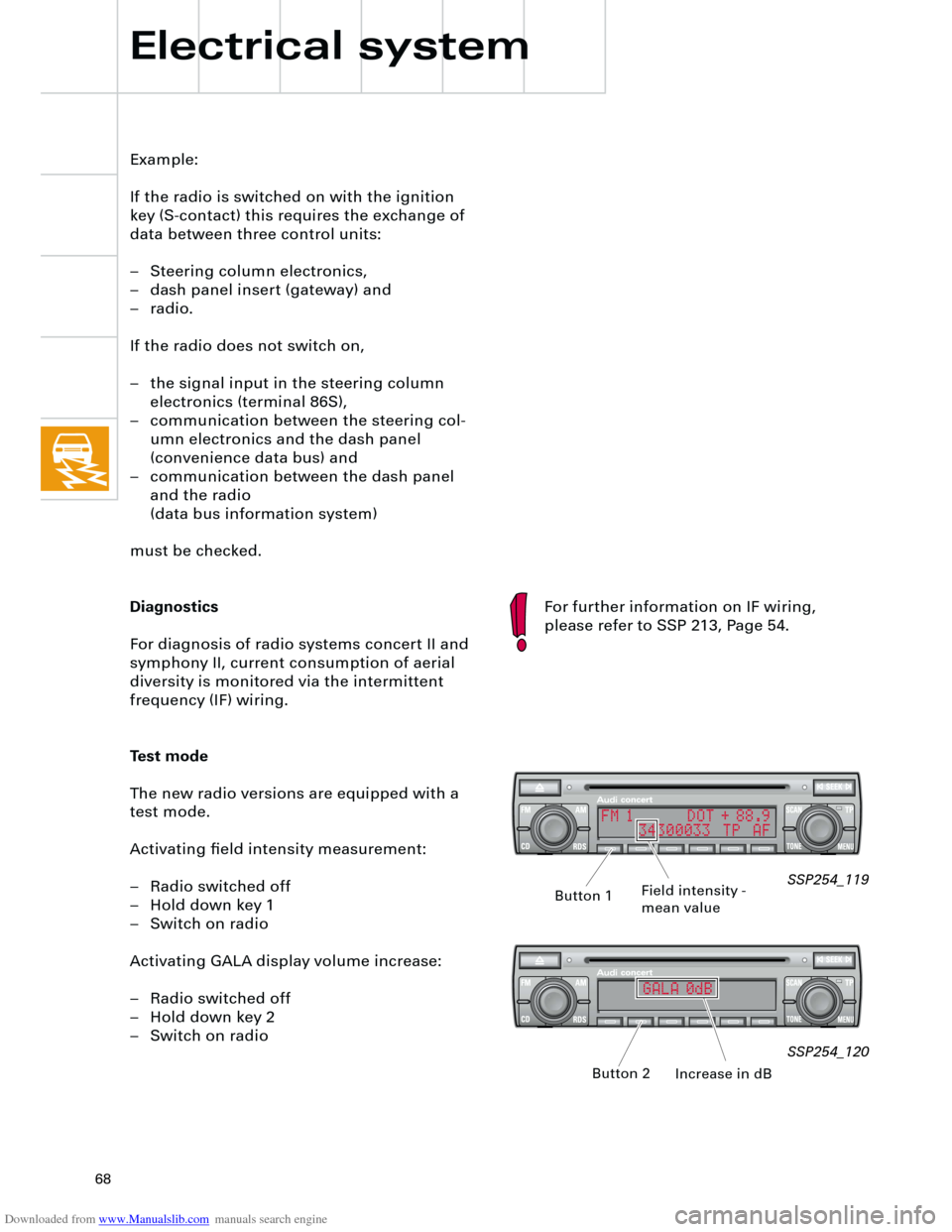
Activating field intensity measurement:
– Radio switched off
– Hold down key 1
– Switch on radio
Activating GALA display volume increase:
– Radio switched off
– Hold down key 2
– Switch on radio
Electrical system
SSP254_119
SSP254_120
Field intensity -
mean value
Increase in dB Button 1
Button 2
For further information on IF wiring,
please refer to SSP 213, Page 54.
FM 1 DOT + 88.9
34300033 TP AF
GALA 0dB
Page 71 of 88
Downloaded from www.Manualslib.com manuals search engine
71
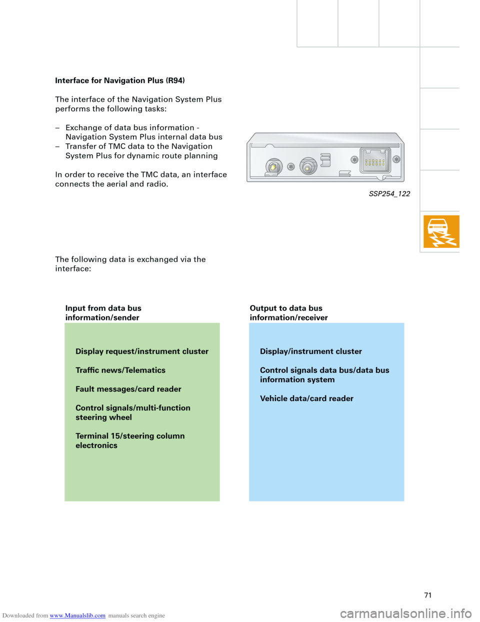
Interface for Navigation Plus (R94)
The interface of the Navigation System Plus
performs the following tasks:
– Exchange of data bus information -
Navigation System Plus internal data bus
– Transfer of TMC data to the Navigation
System Plus for dynamic route planning
In order to receive the TMC data, an interface
connects the aerial and radio.
The following data is exchanged via the
interface:
Display request/instrument cluster
Traffic news/Telematics
Fault messages/card reader
Control signals/multi-function
steering wheel
Terminal 15/steering column
electronicsDisplay/instrument cluster
Control signals data bus/data bus
information system
Vehicle data/card reader Input from data bus
information/senderOutput to data bus
information/receiver
SSP254_122
Page 73 of 88
Downloaded from www.Manualslib.com manuals search engine
73
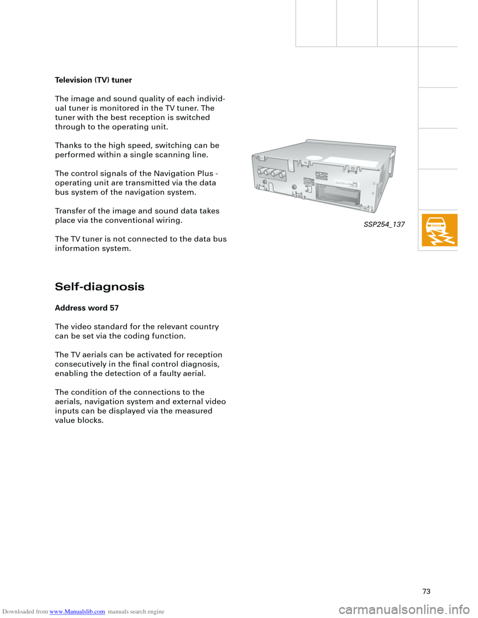
Television (TV) tuner
The image and sound quality of each individ-
ual tuner is monitored in the TV tuner. The
tuner with the best reception is switched
through to the operating unit.
Thanks to the high speed, switching can be
performed within a single scanning line.
The control signals of the Navigation Plus -
operating unit are transmitted via the data
bus system of the navigation system.
Transfer of the image and sound data takes
place via the conventional wiring.
The TV tuner is not connected to the data bus
information system.
Self-diagnosis
Address word 57
The video standard for the relevant country
can be set via the coding function.
The TV aerials can be activated for reception
consecutively in the final control diagnosis,
enabling the detection of a faulty aerial.
The condition of the connections to the
aerials, navigation system and external video
inputs can be displayed via the measured
value blocks.
SSP254_137
Page 75 of 88
Downloaded from www.Manualslib.com manuals search engine
75
In the ”business journey” mode, data relating
to
– date
– time at start of journey
– position at start of journey
– position at end of journey
– time at end of journey
– kilometres driven
are stored in the Chip card reader R99.
The date and route driven are stored In the
”private journey” mode.
The ”continue journey” mode is used to pre-
vent short breaks from being stored (e.g. refu-
elling stops).
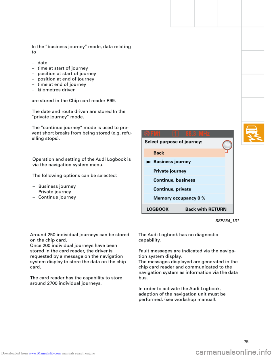
Operation and setting of the Audi Logbook is
via the navigation system menu.
The following options can be selected:
– Business journey
– Private journey
– Continue journey
Around 250 individual journeys can be stored
on the chip card.
Once 200 individual journeys have been
stored in the card reader, the driver is
requested by a message on the navigation
system display to store the data on the chip
card.
The card reader has the capability to store
around 2700 individual journeys.The Audi Logbook has no diagnostic
capability.
Fault messages are indicated via the naviga-
tion system display.
The messages displayed are generated in the
chip card reader and communicated to the
navigation system as information via the data
bus.
In order to activate the Audi Logbook,
adaption of the navigation unit must be
performed. (see workshop manual).
Select purpose of journey:
Back
Business journey
Private journey
Continue, business
Continue, private
Memory occupancy 0 %
LOGBOOK Back with RETURN
SSP254_131
Page 76 of 88
Downloaded from www.Manualslib.com manuals search engine
76
Heater/AC
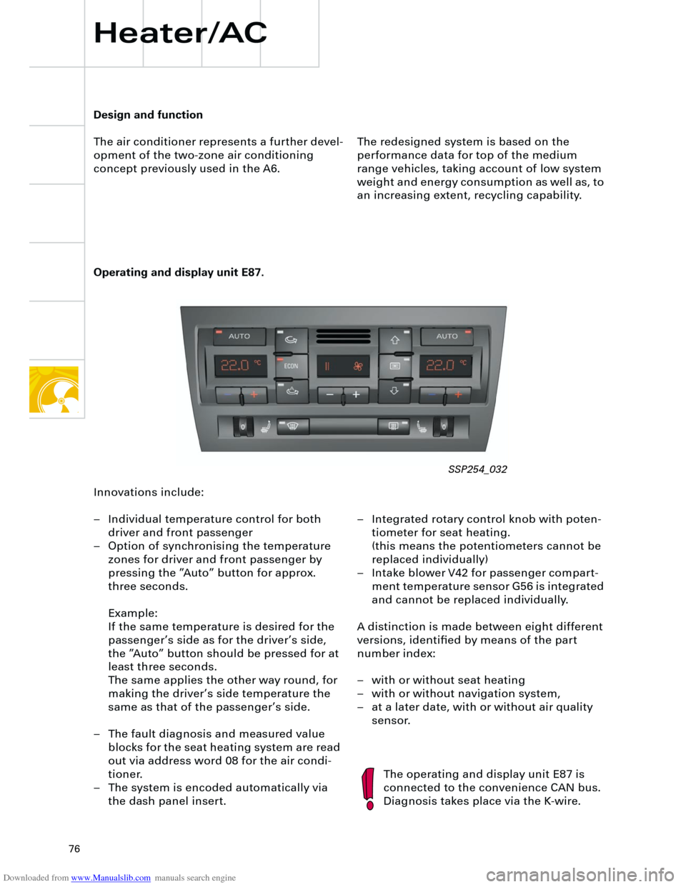
Operating and display unit E87.
The redesigned system is based on the
performance data for top of the medium
range vehicles, taking account of low system
weight and energy consumption as well as, to
an increasing extent, recycling capability.
The operating and display unit E87 is
connected to the convenience CAN bus.
Diagnosis takes place via the K-wire.
Design and function
The air conditioner represents a further devel-
opment of the two-zone air conditioning
concept previously used in the A6.
Innovations include:
– Individual temperature control for both
driver and front passenger
– Option of synchronising the temperature
zones for driver and front passenger by
pressing the ”Auto” button for approx.
three seconds.
Example:
If the same temperature is desired for the
passenger’s side as for the driver’s side,
the ”Auto” button should be pressed for at
least three seconds.
The same applies the other way round, for
making the driver’s side temperature the
same as that of the passenger’s side.
– The fault diagnosis and measured value
blocks for the seat heating system are read
out via address word 08 for the air condi-
tioner.
– The system is encoded automatically via
the dash panel insert.– Integrated rotary control knob with poten-
tiometer for seat heating.
(this means the potentiometers cannot be
replaced individually)
– Intake blower V42 for passenger compart-
ment temperature sensor G56 is integrated
and cannot be replaced individually.
A distinction is made between eight different
versions, identified by means of the part
number index:
– with or without seat heating
– with or without navigation system,
– at a later date, with or without air quality
sensor.
SSP254_032
Page 81 of 88

Downloaded from www.Manualslib.com manuals search engine
81
Fresh air blower
Control technology has been integrated in the
new fresh air blower.
It includes the following features:
– Integrated control unit with diagnostic
capability via the operating and display
unit E87 (fault memory and measured
value block diagnosis-capable control
unit),
– optimised bearings for smoother running,
– separate solar input.
The required blower speed is calculated in the
operating and display unit E87, and requested
by the control unit for fresh air blower J126
via a PWM signal.In the case of malfunctions, such as e.g. a stiff
or blocked blower, this is signalled to the
operating and display unit E87 by duty cycle
changes based on the altered frequency. The
relevant fault is set.
The blower bearings have been re-engineered
in order to optimise the effectiveness of the
system.
This particularly benefits solar operation.
The energy supplied by the solar roof is
utilised to drive the fresh air blower by means
of special electronics via the separate solar
input in the blower.
SSP254_037
Page 82 of 88
Downloaded from www.Manualslib.com manuals search engine
82
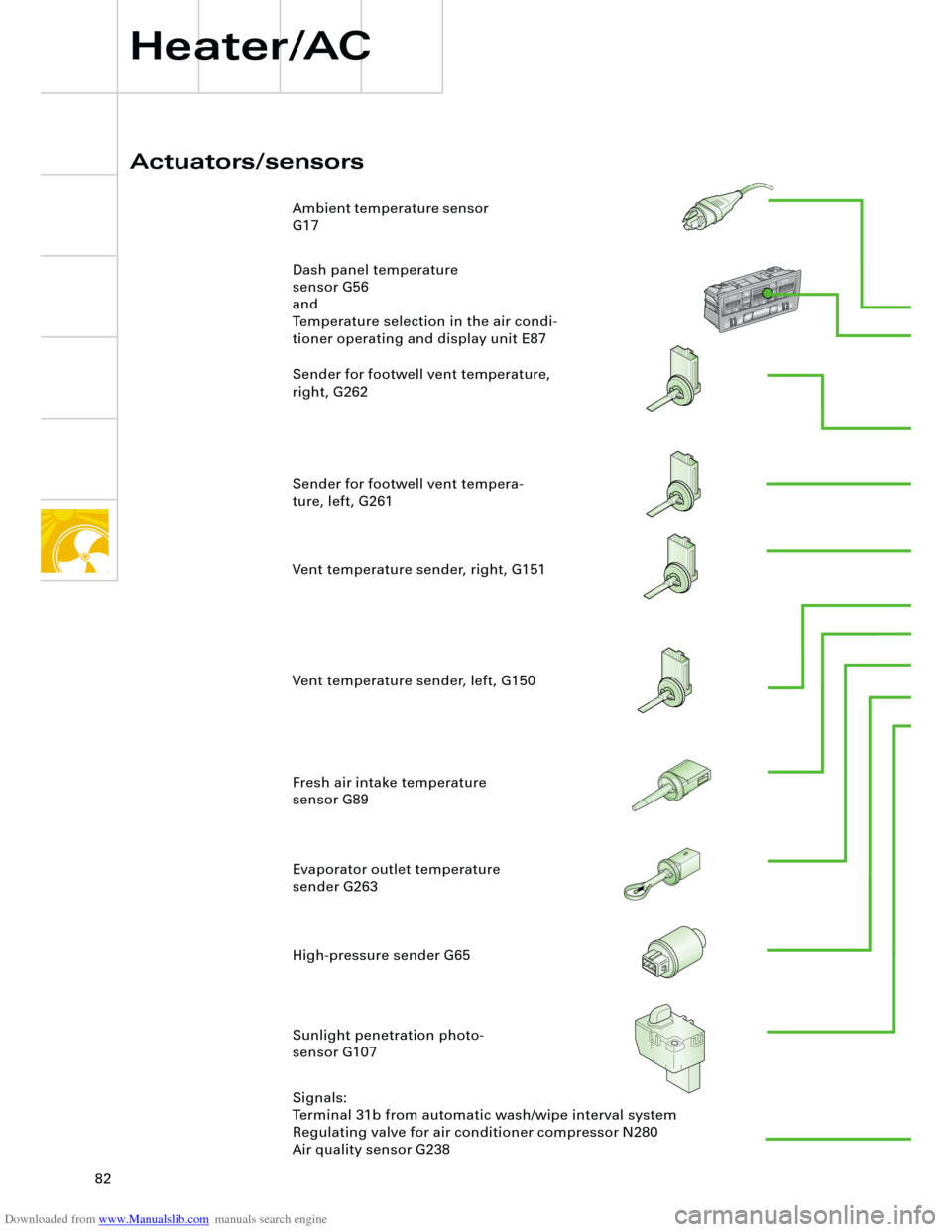
Actuators/sensors
Heater/AC
Ambient temperature sensor
G17
Dash panel temperature
sensor G56
and
Temperature selection in the air condi-
tioner operating and display unit E87
Sender for footwell vent temperature,
right, G262
Sender for footwell vent tempera-
ture, left, G261
High-pressure sender G65 Evaporator outlet temperature
sender G263 Fresh air intake temperature
sensor G89
Sunlight penetration photo-
sensor G107
Signals:
Terminal 31b from automatic wash/wipe interval system
Regulating valve for air conditioner compressor N280
Air quality sensor G238 Vent temperature sender, right, G151
Vent temperature sender, left, G150
E
C
O
NO
F
F
Page 83 of 88
Downloaded from www.Manualslib.com manuals search engine
83
153.95244km9:3628.07.2000
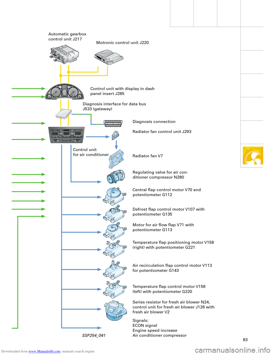
Diagnosis connection
Radiator fan control unit J293
Radiator fan V7
Regulating valve for air con-
ditioner compressor N280
Central flap control motor V70 and
potentiometer G112 Control unit
for air conditioner Automatic gearbox
control unit J217
Motronic control unit J220
Defrost flap control motor V107 with
potentiometer G135
Motor for air flow flap V71 with
potentiometer G113
Temperature flap positioning motor V158
(right) with potentiometer G221
Series resistor for fresh air blower N24,
control unit for fresh air blower J126 with
fresh air blower V2
Signals:
ECON signal
Engine speed increase
Air conditioner compressor Control unit with display in dash
panel insert J285
Diagnosis interface for data bus
J533 (gateway)
Air recirculation flap control motor V113
for potentiometer G143
Temperature flap control motor V158
(left) with potentiometer G220
SSP254_041
Page 84 of 88
Downloaded from www.Manualslib.com manuals search engine
84
Heater/AC
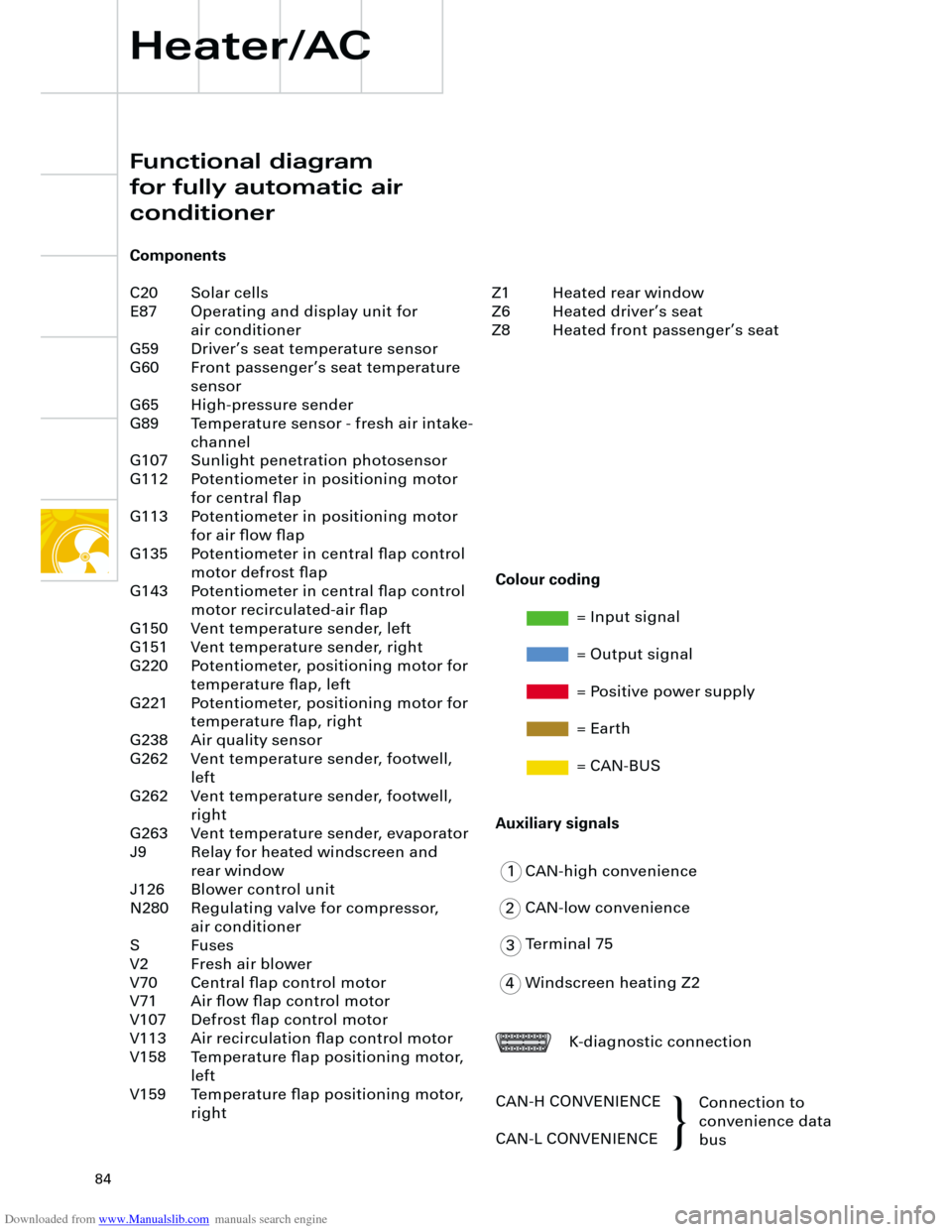
Functional diagram
for fully automatic air
conditioner
Components
C20 Solar cells
E87 Operating and display unit for
air conditioner
G59 Driver’s seat temperature sensor
G60 Front passenger’s seat temperature
sensor
G65 High-pressure sender
G89 Temperature sensor - fresh air intake-
channel
G107 Sunlight penetration photosensor
G112 Potentiometer in positioning motor
for central flap
G113 Potentiometer in positioning motor
for air flow flap
G135 Potentiometer in central flap control
motor defrost flap
G143 Potentiometer in central flap control
motor recirculated-air flap
G150 Vent temperature sender, left
G151 Vent temperature sender, right
G220 Potentiometer, positioning motor for
temperature flap, left
G221 Potentiometer, positioning motor for
temperature flap, right
G238 Air quality sensor
G262 Vent temperature sender, footwell,
left
G262 Vent temperature sender, footwell,
right
G263 Vent temperature sender, evaporator
J9 Relay for heated windscreen and
rear window
J126 Blower control unit
N280 Regulating valve for compressor,
air conditioner
S Fuses
V2 Fresh air blower
V70 Central flap control motor
V71 Air flow flap control motor
V107 Defrost flap control motor
V113 Air recirculation flap control motor
V158 Temperature flap positioning motor,
left
V159 Temperature flap positioning motor,
right
1
2
3
4CAN-high convenience
CAN-low convenience
Terminal 75
Windscreen heating Z2
K-diagnostic connection
CAN-H CONVENIENCE
CAN-L CONVENIENCEConnection to
convenience data
bus
Colour coding
= Input signal
= Output signal
= Positive power supply
= Earth
= CAN-BUS
Auxiliary signals
Z1 Heated rear window
Z6 Heated driver’s seat
Z8 Heated front passenger’s seat
{