brake AUDI A4 2001 B5 / 1.G Technical Features Design And Function
[x] Cancel search | Manufacturer: AUDI, Model Year: 2001, Model line: A4, Model: AUDI A4 2001 B5 / 1.GPages: 88, PDF Size: 10.42 MB
Page 2 of 88
Downloaded from www.Manualslib.com manuals search engine
2
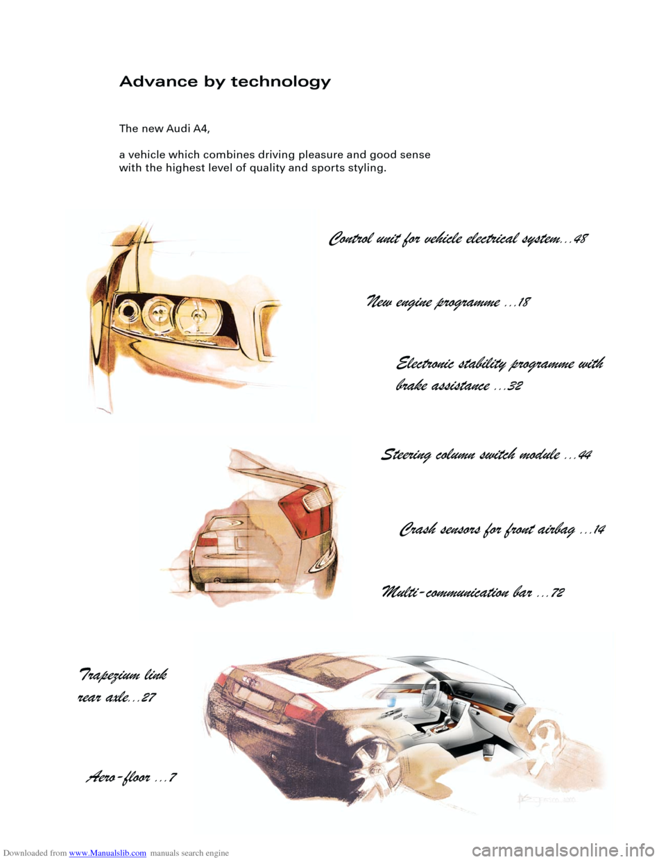
Advance by technology
The new Audi A4,
a vehicle which combines driving pleasure and good sense
with the highest level of quality and sports styling.
Control unit for vehicle electrical system
...48
New engine programme
...18
Electronic stability programme with
brake assistance
...32
Steering column switch module
...44
Crash sensors for front airbag
...14
Multi-communication bar
...72
Trapezium link
rear axle
...27
Aero-floor
...7
Page 3 of 88
Downloaded from www.Manualslib.com manuals search engine
3
Important:
Note
New
Contents
It is not intended as a workshop manual.
The self-study programme will provide you with information on
design and functions.
For maintenance and repair operations it is essential that you
refer to the current technical literature.
Page
Introduction . . . . . . . . . . . . . . . . . . . . . . . . . . . . . . . . . . . . . . . . . . 4
Body . . . . . . . . . . . . . . . . . . . . . . . . . . . . . . . . . . . . . . . . . . . . . . . . 8
Occupant protection . . . . . . . . . . . . . . . . . . . . . . . . . . . . . . . . 12
Engine and gearbox
Running gear
Axles . . . . . . . . . . . . . . . . . . . . . . . . . . . . . . . . . . . . . . . . . . . . . . . . . . . . . . . . . . . . 26
Mechanical unit mountings . . . . . . . . . . . . . . . . . . . . . . . . . . . . . . . . . . . . . . . . . . . 28
Brake system . . . . . . . . . . . . . . . . . . . . . . . . . . . . . . . . . . . . . . . . . . . . . . . . . . . . . . . 29
Brake assistance . . . . . . . . . . . . . . . . . . . . . . . . . . . . . . . . . . . . . . . . . . . . . . . . . . . . 32
Vehicle electrical system . . . . . . . . . . . . . . . . . . . . . . . . . . . . . . . . . . . . . . . . . . . . . . 36
CAN BUS system . . . . . . . . . . . . . . . . . . . . . . . . . . . . . . . . . . . . . . . . . . . . . . . . . . . . 38
Dash panel insert . . . . . . . . . . . . . . . . . . . . . . . . . . . . . . . . . . . . . . . . . . . . . . . . . . . . 40
Steering column switch module . . . . . . . . . . . . . . . . . . . . . . . . . . . . . . . . . . . . . . . .44
Function circuit diagram . . . . . . . . . . . . . . . . . . . . . . . . . . . . . . . . . . . . . . . 46
Control unit for vehicle electrical system . . . . . . . . . . . . . . . . . . . . . . . . . . . . . . . . 48
Function circuit diagram for "lowline" version . . . . . . . . . . . . . . . . . . . . . 50
Function circuit diagram for "highline" version . . . . . . . . . . . . . . . . . . . . 52
Convenience system . . . . . . . . . . . . . . . . . . . . . . . . . . . . . . . . . . . . . . . . . . . . . . . . . 58
Anti-theft alarm system . . . . . . . . . . . . . . . . . . . . . . . . . . . . . . . . . . . . . . . . . . . . . . . 63
Radio - chorus II, concert II and symphony II . . . . . . . . . . . . . . . . . . . . . . . . . . . . . 65
Navigation IV and Navigation Plus-D . . . . . . . . . . . . . . . . . . . . . . . . . . . . . . . . . . . . 69
Multi-communication bar . . . . . . . . . . . . . . . . . . . . . . . . . . . . . . . . . . . . . . . . . . . . . 72
Electric logbook "Audi Logbook" . . . . . . . . . . . . . . . . . . . . . . . . . . . . . . . . . . . . . . . 74
Heater/AC
Design and function . . . . . . . . . . . . . . . . . . . . . . . . . . . . . . . . . . . . . . . . . . . . . . . . . 76
7-piston compressor . . . . . . . . . . . . . . . . . . . . . . . . . . . . . . . . . . . . . . . . . . . . . . . . . 77
Air conditioner . . . . . . . . . . . . . . . . . . . . . . . . . . . . . . . . . . . . . . . . . . . . . . . . . . . . . . 78
Glove compartment cooling . . . . . . . . . . . . . . . . . . . . . . . . . . . . . . . . . . . . . . . . . . . 79
Solar roof . . . . . . . . . . . . . . . . . . . . . . . . . . . . . . . . . . . . . . . . . . . . . . . . . . . . . . . . . . . 80
Fresh air blower . . . . . . . . . . . . . . . . . . . . . . . . . . . . . . . . . . . . . . . . . . . . . . . . . . . . . 81
Actuators/sensors . . . . . . . . . . . . . . . . . . . . . . . . . . . . . . . . . . . . . . . . . . . . . . . . . . . 82
Functional diagram for fully automatic air conditioner . . . . . . . . . . . . . . 84
Additional heater . . . . . . . . . . . . . . . . . . . . . . . . . . . . . . . . . . . . . . . . . . . . . . . . . . . . 86 2.0 l R4 and 3.0 l V6 engines (see SSP 255) . . . . . . . . . . . . . . . . . . . . . . . . . . . . . . . 18
Innovations - 2.5 l V6 TDI engine. . . . . . . . . . . . . . . . . . . . . . . . . . . . . . . . . . . . . . . . 19
Innovations - automatic gearbox . . . . . . . . . . . . . . . . . . . . . . . . . . . . . . . . . . . . . . . 23
Electrical system
Page 5 of 88
Downloaded from www.Manualslib.com manuals search engine
5
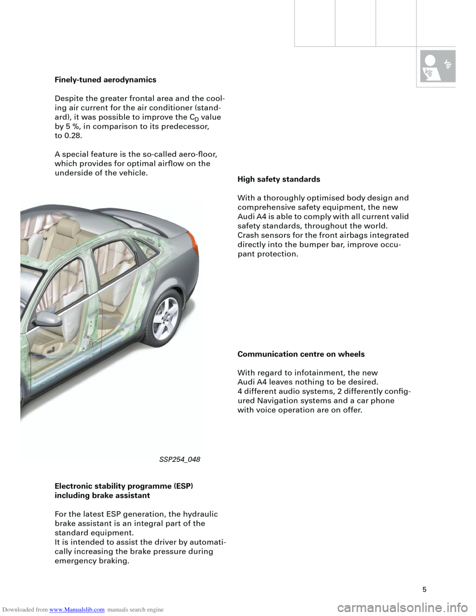
High safety standards
With a thoroughly optimised body design and
comprehensive safety equipment, the new
Audi A4 is able to comply with all current valid
safety standards, throughout the world.
Crash sensors for the front airbags integrated
directly into the bumper bar, improve occu-
pant protection.
Finely-tuned aerodynamics
Despite the greater frontal area and the cool-
ing air current for the air conditioner (stand-
ard), it was possible to improve the C
D
value
by 5 %, in comparison to its predecessor,
to 0.28.
A special feature is the so-called aero-floor,
which provides for optimal airflow on the
underside of the vehicle.
Communication centre on wheels
With regard to infotainment, the new
Audi A4 leaves nothing to be desired.
4 different audio systems, 2 differently config-
ured Navigation systems and a car phone
with voice operation are on offer.
Electronic stability programme (ESP)
including brake assistant
For the latest ESP generation, the hydraulic
brake assistant is an integral part of the
standard equipment.
It is intended to assist the driver by automati-
cally increasing the brake pressure during
emergency braking.
SSP254_048
Page 29 of 88
Downloaded from www.Manualslib.com manuals search engine
29
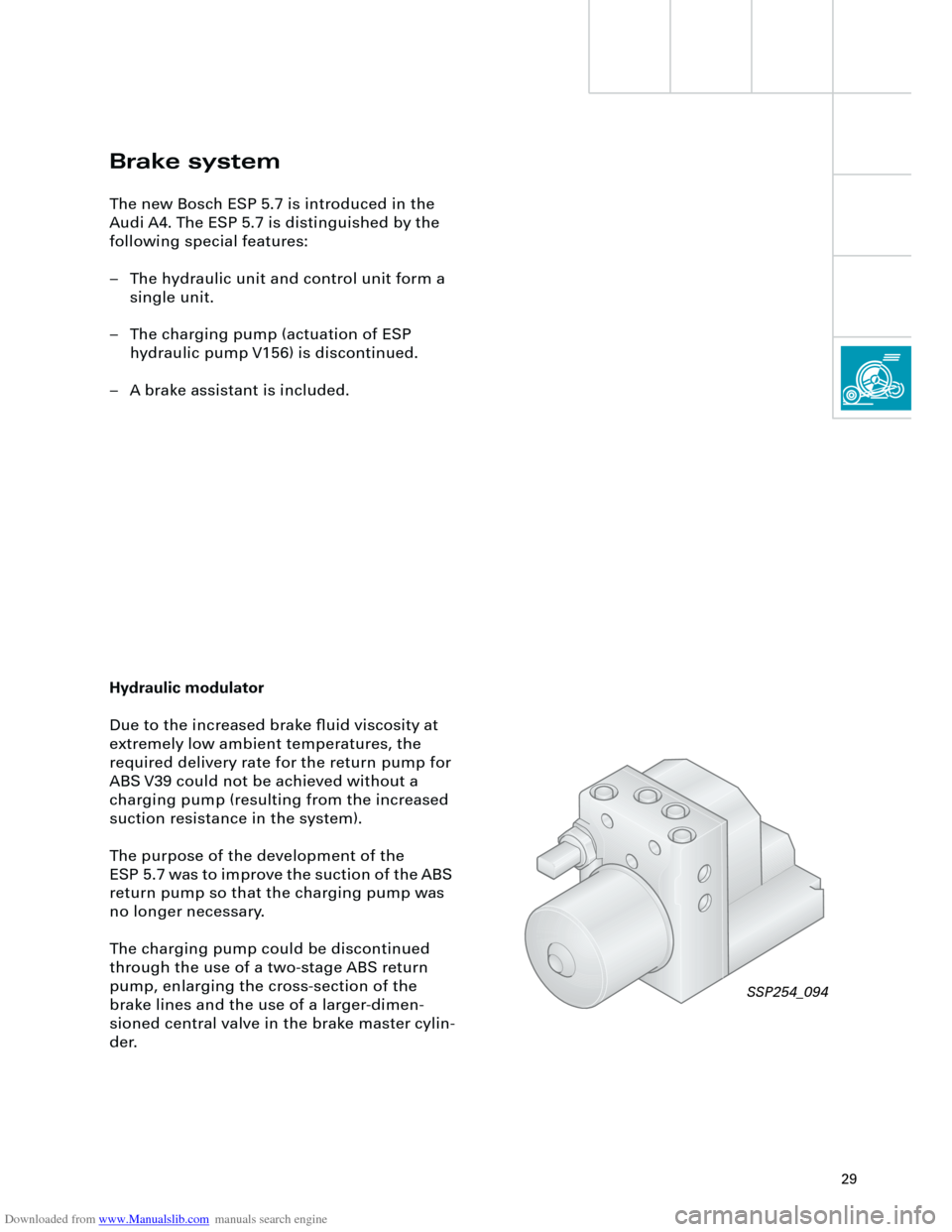
Brake system
The new Bosch ESP 5.7 is introduced in the
Audi A4. The ESP 5.7 is distinguished by the
following special features:
– The hydraulic unit and control unit form a
single unit.
– The charging pump (actuation of ESP
hydraulic pump V156) is discontinued.
– A brake assistant is included.
Hydraulic modulator
Due to the increased brake fluid viscosity at
extremely low ambient temperatures, the
required delivery rate for the return pump for
ABS V39 could not be achieved without a
charging pump (resulting from the increased
suction resistance in the system).
The purpose of the development of the
ESP 5.7 was to improve the suction of the ABS
return pump so that the charging pump was
no longer necessary.
The charging pump could be discontinued
through the use of a two-stage ABS return
pump, enlarging the cross-section of the
brake lines and the use of a larger-dimen-
sioned central valve in the brake master cylin-
der.
SSP254_094
Page 31 of 88
Downloaded from www.Manualslib.com manuals search engine
31
UTUTOTOT
UTUTOTOT
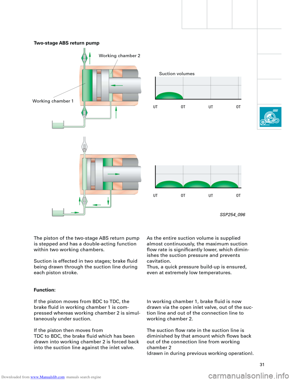
The piston of the two-stage ABS return pump
is stepped and has a double-acting function
within two working chambers.
Suction is effected in two stages; brake fluid
being drawn through the suction line during
each piston stroke.
Function:
If the piston moves from BDC to TDC, the
brake fluid in working chamber 1 is com-
pressed whereas working chamber 2 is simul-
taneously under suction.
If the piston then moves from
TDC to BDC, the brake fluid which has been
drawn into working chamber 2 is forced back
into the suction line against the inlet valve.As the entire suction volume is supplied
almost continuously, the maximum suction
flow rate is significantly lower, which dimin-
ishes the suction pressure and prevents
cavitation.
Thus, a quick pressure build-up is ensured,
even at extremely low temperatures.
In working chamber 1, brake fluid is now
drawn via the open inlet valve, out of the suc-
tion line and out of the connection line to
working chamber 2.
The suction flow rate in the suction line is
diminished by that amount which flows back
out of the connection line from working
chamber 2
(drawn in during previous working operation).
Two-stage ABS return pump
Working chamber 1Working chamber 2
Suction volumes
SSP254_096
Page 32 of 88
Downloaded from www.Manualslib.com manuals search engine
32
Brake assistant
Investigations in accident research have
shown, that the majority of drivers fail to ade-
quately actuate the brakes in an emergency
situation.
This results in insufficient brake pressure
being generated to achieve maximum vehicle
deceleration.
This lengthens the braking distance.During emergency braking, the brake assist-
ant aids the driver by increasing the brake
pressure automatically, to a level exceeding
the locking limit.
The ABS (
A
nti-lock
b
raking
s
ystem) is thus
quickly brought into the operating range,
which enables a maximum vehicle decelera-
tion to be achieved.
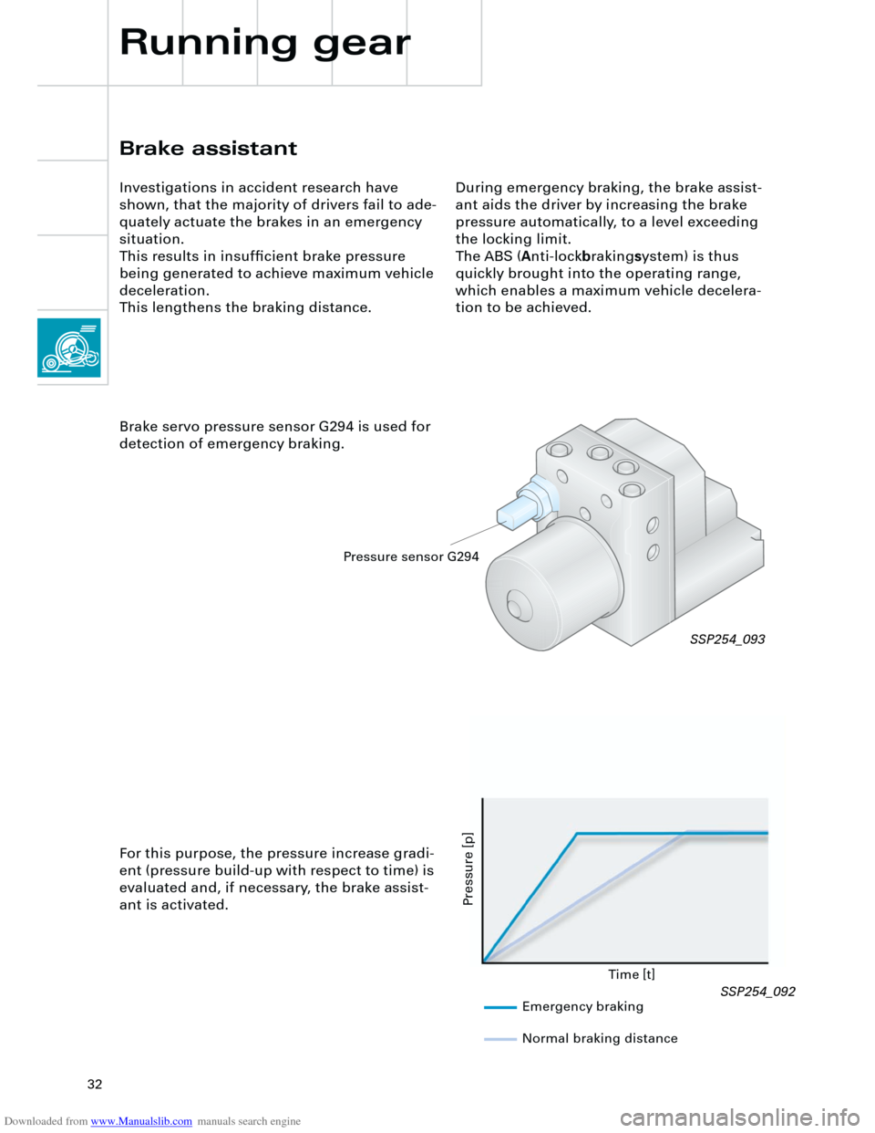
Brake servo pressure sensor G294 is used for
detection of emergency braking.
Time [t]
Pressure [p]
For this purpose, the pressure increase gradi-
ent (pressure build-up with respect to time) is
evaluated and, if necessary, the brake assist-
ant is activated.
SSP254_093
Emergency braking
Normal braking distance
Pressure sensor G294
Running gear
SSP254_092
Page 33 of 88
Downloaded from www.Manualslib.com manuals search engine
33
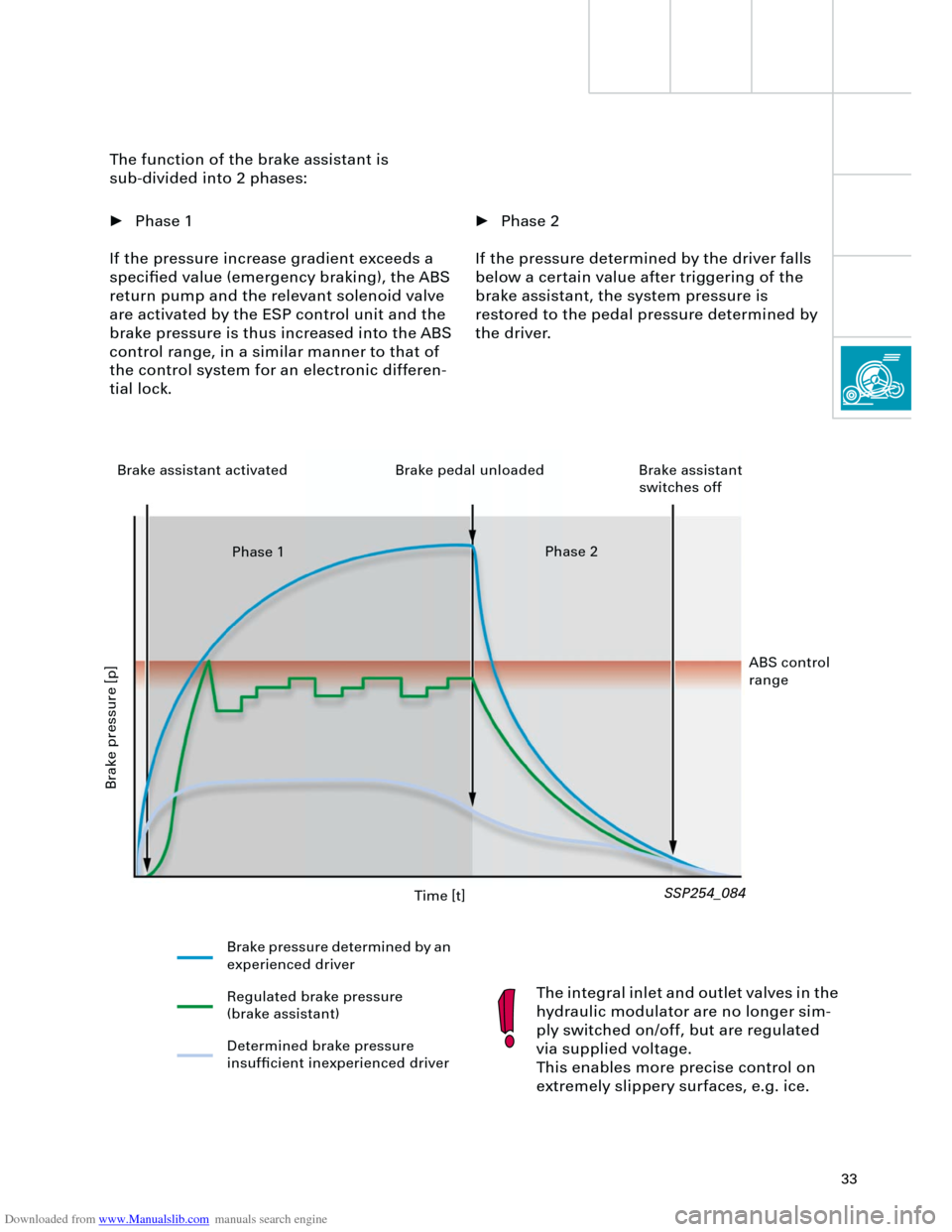
• Phase 2
If the pressure determined by the driver falls
below a certain value after triggering of the
brake assistant, the system pressure is
restored to the pedal pressure determined by
the driver. The function of the brake assistant is
sub-divided into 2 phases:
• Phase 1
If the pressure increase gradient exceeds a
specified value (emergency braking), the ABS
return pump and the relevant solenoid valve
are activated by the ESP control unit and the
brake pressure is thus increased into the ABS
control range, in a similar manner to that of
the control system for an electronic differen-
tial lock.
The integral inlet and outlet valves in the
hydraulic modulator are no longer sim-
ply switched on/off, but are regulated
via supplied voltage.
This enables more precise control on
extremely slippery surfaces, e.g. ice.
SSP254_084
Time [t]
Brake pressure [p]
Brake pressure determined by an
experienced driver
Regulated brake pressure
(brake assistant)
Determined brake pressure
insufficient inexperienced driver Brake assistant activated Brake pedal unloaded Brake assistant
switches off
Phase 1Phase 2
ABS control
range
Page 34 of 88
Downloaded from www.Manualslib.com manuals search engine
34
Running gear
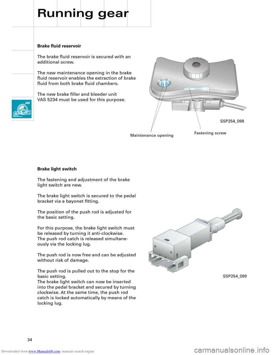
Brake fluid reservoir
The brake fluid reservoir is secured with an
additional screw.
The new maintenance opening in the brake
fluid reservoir enables the extraction of brake
fluid from both brake fluid chambers.
The new brake filler and bleeder unit
VAS 5234 must be used for this purpose.
Brake light switch
The fastening and adjustment of the brake
light switch are new.
The brake light switch is secured to the pedal
bracket via a bayonet fitting.
The position of the push rod is adjusted for
the basic setting.
For this purpose, the brake light switch must
be released by turning it anti-clockwise.
The push rod catch is released simultane-
ously via the locking lug.
The push rod is now free and can be adjusted
without risk of damage.
The push rod is pulled out to the stop for the
basic setting.
The brake light switch can now be inserted
into the pedal bracket and secured by turning
clockwise. At the same time, the push rod
catch is locked automatically by means of the
locking lug.
SSP254_098
Maintenance openingFastening screw
SSP254_099
Page 49 of 88
Downloaded from www.Manualslib.com manuals search engine
49
There are three control unit versions:
– "lowline" for the standard version
– "lowline" for vehicles with headlight
washer system
– "highline" for vehicles with driver informa-
tion system
The following functions are available with the
"lowline" version:
– Wash/wipe control and interval
– Hazard warning and turn signal control
– Actuation of horn and load-reduction relay
– Parking light left/right
– Side light left/right
– Main beam left/right and headlight flasher
– Number plate lightThe "highline" version implements the driver
information system function and also
performs the following control functions:
– Driving light and dipped beam left/right,
– Fog lights and rear lights,
– Reversing lights,
– Brake lights
with separate outputs to each of the individ-
ual consumers.
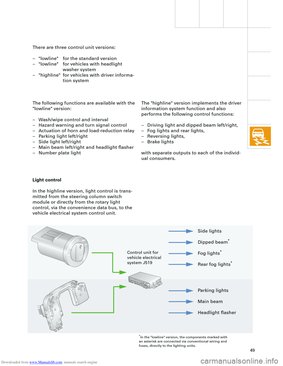
Light control
In the highline version, light control is trans-
mitted from the steering column switch
module or directly from the rotary light
control, via the convenience data bus, to the
vehicle electrical system control unit.
Parking lights
Main beam
Headlight flasher Side lights
Dipped beam
*
Fog lights
*
Rear fog lights
*
*
In the "lowline" version, the components marked with
an asterisk are connected via conventional wiring and
fuses, directly to the lighting units.
Control unit for
vehicle electrical
system J519
Page 50 of 88
Downloaded from www.Manualslib.com manuals search engine
50
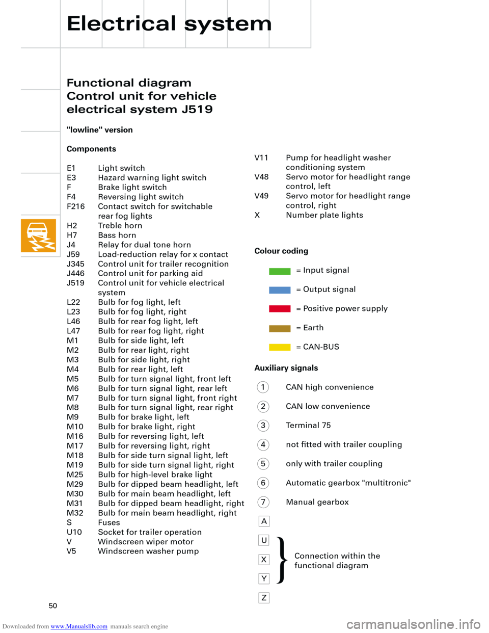
Auxiliary signals
1 CAN high convenience
2 CAN low convenience
3 Terminal 75
4 not fitted with trailer coupling
5 only with trailer coupling
6 Automatic gearbox "multitronic"
7 Manual gearbox
A
U
X
Y
Z
Electrical system
"lowline" version
Components
E1 Light switch
E3 Hazard warning light switch
F Brake light switch
F4 Reversing light switch
F216 Contact switch for switchable
rear fog lights
H2 Treble horn
H7 Bass horn
J4 Relay for dual tone horn
J59 Load-reduction relay for x contact
J345 Control unit for trailer recognition
J446 Control unit for parking aid
J519 Control unit for vehicle electrical
system
L22 Bulb for fog light, left
L23 Bulb for fog light, right
L46 Bulb for rear fog light, left
L47 Bulb for rear fog light, right
M1 Bulb for side light, left
M2 Bulb for rear light, right
M3 Bulb for side light, right
M4 Bulb for rear light, left
M5 Bulb for turn signal light, front left
M6 Bulb for turn signal light, rear left
M7 Bulb for turn signal light, front right
M8 Bulb for turn signal light, rear right
M9 Bulb for brake light, left
M10 Bulb for brake light, right
M16 Bulb for reversing light, left
M17 Bulb for reversing light, right
M18 Bulb for side turn signal light, left
M19 Bulb for side turn signal light, right
M25 Bulb for high-level brake light
M29 Bulb for dipped beam headlight, left
M30 Bulb for main beam headlight, left
M31 Bulb for dipped beam headlight, right
M32 Bulb for main beam headlight, right
S Fuses
U10 Socket for trailer operation
V Windscreen wiper motor
V5 Windscreen washer pump
Colour coding
= Input signal
= Output signal
= Positive power supply
= Earth
= CAN-BUS
V11 Pump for headlight washer
conditioning system
V48 Servo motor for headlight range
control, left
V49 Servo motor for headlight range
control, right
X Number plate lights
Connection within the
functional diagram
Functional diagram
Control unit for vehicle
electrical system J519
{