radio AUDI A4 2001 B5 / 1.G Technical Features Design And Function
[x] Cancel search | Manufacturer: AUDI, Model Year: 2001, Model line: A4, Model: AUDI A4 2001 B5 / 1.GPages: 88, PDF Size: 10.42 MB
Page 3 of 88
Downloaded from www.Manualslib.com manuals search engine
3
Important:
Note
New
Contents
It is not intended as a workshop manual.
The self-study programme will provide you with information on
design and functions.
For maintenance and repair operations it is essential that you
refer to the current technical literature.
Page
Introduction . . . . . . . . . . . . . . . . . . . . . . . . . . . . . . . . . . . . . . . . . . 4
Body . . . . . . . . . . . . . . . . . . . . . . . . . . . . . . . . . . . . . . . . . . . . . . . . 8
Occupant protection . . . . . . . . . . . . . . . . . . . . . . . . . . . . . . . . 12
Engine and gearbox
Running gear
Axles . . . . . . . . . . . . . . . . . . . . . . . . . . . . . . . . . . . . . . . . . . . . . . . . . . . . . . . . . . . . 26
Mechanical unit mountings . . . . . . . . . . . . . . . . . . . . . . . . . . . . . . . . . . . . . . . . . . . 28
Brake system . . . . . . . . . . . . . . . . . . . . . . . . . . . . . . . . . . . . . . . . . . . . . . . . . . . . . . . 29
Brake assistance . . . . . . . . . . . . . . . . . . . . . . . . . . . . . . . . . . . . . . . . . . . . . . . . . . . . 32
Vehicle electrical system . . . . . . . . . . . . . . . . . . . . . . . . . . . . . . . . . . . . . . . . . . . . . . 36
CAN BUS system . . . . . . . . . . . . . . . . . . . . . . . . . . . . . . . . . . . . . . . . . . . . . . . . . . . . 38
Dash panel insert . . . . . . . . . . . . . . . . . . . . . . . . . . . . . . . . . . . . . . . . . . . . . . . . . . . . 40
Steering column switch module . . . . . . . . . . . . . . . . . . . . . . . . . . . . . . . . . . . . . . . .44
Function circuit diagram . . . . . . . . . . . . . . . . . . . . . . . . . . . . . . . . . . . . . . . 46
Control unit for vehicle electrical system . . . . . . . . . . . . . . . . . . . . . . . . . . . . . . . . 48
Function circuit diagram for "lowline" version . . . . . . . . . . . . . . . . . . . . . 50
Function circuit diagram for "highline" version . . . . . . . . . . . . . . . . . . . . 52
Convenience system . . . . . . . . . . . . . . . . . . . . . . . . . . . . . . . . . . . . . . . . . . . . . . . . . 58
Anti-theft alarm system . . . . . . . . . . . . . . . . . . . . . . . . . . . . . . . . . . . . . . . . . . . . . . . 63
Radio - chorus II, concert II and symphony II . . . . . . . . . . . . . . . . . . . . . . . . . . . . . 65
Navigation IV and Navigation Plus-D . . . . . . . . . . . . . . . . . . . . . . . . . . . . . . . . . . . . 69
Multi-communication bar . . . . . . . . . . . . . . . . . . . . . . . . . . . . . . . . . . . . . . . . . . . . . 72
Electric logbook "Audi Logbook" . . . . . . . . . . . . . . . . . . . . . . . . . . . . . . . . . . . . . . . 74
Heater/AC
Design and function . . . . . . . . . . . . . . . . . . . . . . . . . . . . . . . . . . . . . . . . . . . . . . . . . 76
7-piston compressor . . . . . . . . . . . . . . . . . . . . . . . . . . . . . . . . . . . . . . . . . . . . . . . . . 77
Air conditioner . . . . . . . . . . . . . . . . . . . . . . . . . . . . . . . . . . . . . . . . . . . . . . . . . . . . . . 78
Glove compartment cooling . . . . . . . . . . . . . . . . . . . . . . . . . . . . . . . . . . . . . . . . . . . 79
Solar roof . . . . . . . . . . . . . . . . . . . . . . . . . . . . . . . . . . . . . . . . . . . . . . . . . . . . . . . . . . . 80
Fresh air blower . . . . . . . . . . . . . . . . . . . . . . . . . . . . . . . . . . . . . . . . . . . . . . . . . . . . . 81
Actuators/sensors . . . . . . . . . . . . . . . . . . . . . . . . . . . . . . . . . . . . . . . . . . . . . . . . . . . 82
Functional diagram for fully automatic air conditioner . . . . . . . . . . . . . . 84
Additional heater . . . . . . . . . . . . . . . . . . . . . . . . . . . . . . . . . . . . . . . . . . . . . . . . . . . . 86 2.0 l R4 and 3.0 l V6 engines (see SSP 255) . . . . . . . . . . . . . . . . . . . . . . . . . . . . . . . 18
Innovations - 2.5 l V6 TDI engine. . . . . . . . . . . . . . . . . . . . . . . . . . . . . . . . . . . . . . . . 19
Innovations - automatic gearbox . . . . . . . . . . . . . . . . . . . . . . . . . . . . . . . . . . . . . . . 23
Electrical system
Page 11 of 88
Downloaded from www.Manualslib.com manuals search engine
11
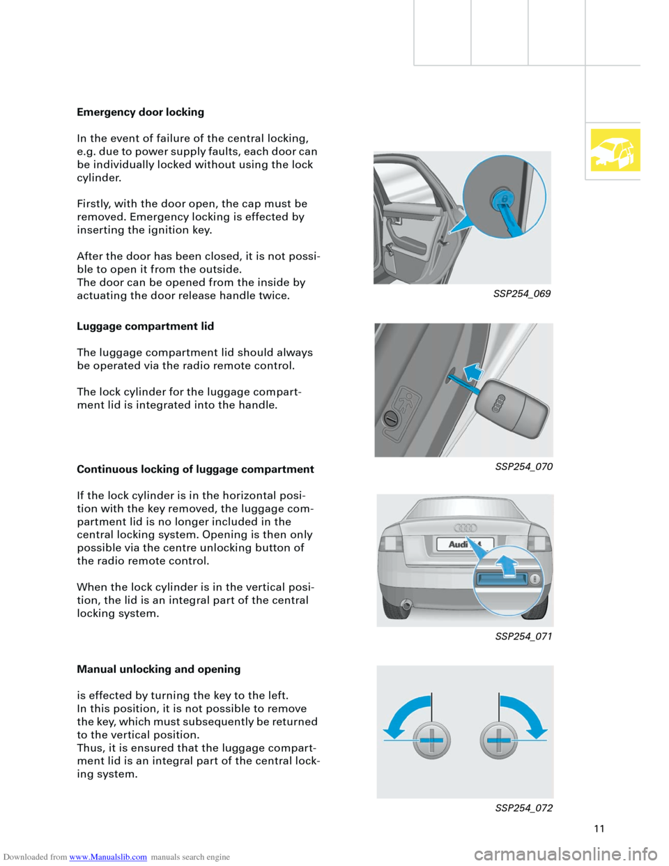
Luggage compartment lid
The luggage compartment lid should always
be operated via the radio remote control.
The lock cylinder for the luggage compart-
ment lid is integrated into the handle.
Emergency door locking
In the event of failure of the central locking,
e.g. due to power supply faults, each door can
be individually locked without using the lock
cylinder.
Firstly, with the door open, the cap must be
removed. Emergency locking is effected by
inserting the ignition key.
After the door has been closed, it is not possi-
ble to open it from the outside.
The door can be opened from the inside by
actuating the door release handle twice.
Continuous locking of luggage compartment
If the lock cylinder is in the horizontal posi-
tion with the key removed, the luggage com-
partment lid is no longer included in the
central locking system. Opening is then only
possible via the centre unlocking button of
the radio remote control.
When the lock cylinder is in the vertical posi-
tion, the lid is an integral part of the central
locking system.
Manual unlocking and opening
is effected by turning the key to the left.
In this position, it is not possible to remove
the key, which must subsequently be returned
to the vertical position.
Thus, it is ensured that the luggage compart-
ment lid is an integral part of the central lock-
ing system.
SSP254_069
SSP254_070
SSP254_071
SSP254_072
Page 39 of 88
Downloaded from www.Manualslib.com manuals search engine
39
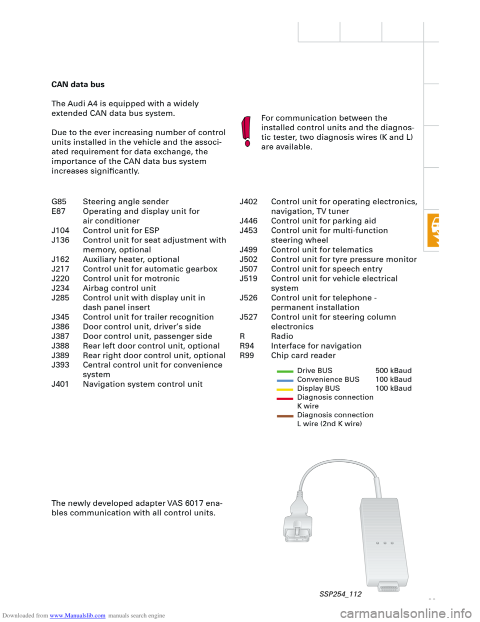
CAN data bus
The Audi A4 is equipped with a widely
extended CAN data bus system.
Due to the ever increasing number of control
units installed in the vehicle and the associ-
ated requirement for data exchange, the
importance of the CAN data bus system
increases significantly.For communication between the
installed control units and the diagnos-
tic tester, two diagnosis wires (K and L)
are available.
The newly developed adapter VAS 6017 ena-
bles communication with all control units.
Drive BUS 500 kBaud
Convenience BUS 100 kBaud
Display BUS 100 kBaud
Diagnosis connection
K wire
Diagnosis connection
L wire (2nd K wire)
J402 Control unit for operating electronics,
navigation, TV tuner
J446 Control unit for parking aid
J453 Control unit for multi-function
steering wheel
J499 Control unit for telematics
J502 Control unit for tyre pressure monitor
J507 Control unit for speech entry
J519 Control unit for vehicle electrical
system
J526 Control unit for telephone -
permanent installation
J527 Control unit for steering column
electronics
R Radio
R94 Interface for navigation
R99 Chip card reader G85 Steering angle sender
E87 Operating and display unit for
air conditioner
J104 Control unit for ESP
J136 Control unit for seat adjustment with
memory, optional
J162 Auxiliary heater, optional
J217 Control unit for automatic gearbox
J220 Control unit for motronic
J234 Airbag control unit
J285 Control unit with display unit in
dash panel insert
J345 Control unit for trailer recognition
J386 Door control unit, driver’s side
J387 Door control unit, passenger side
J388 Rear left door control unit, optional
J389 Rear right door control unit, optional
J393 Central control unit for convenience
system
J401 Navigation system control unit
SSP254_112
Page 41 of 88
Downloaded from www.Manualslib.com manuals search engine
41
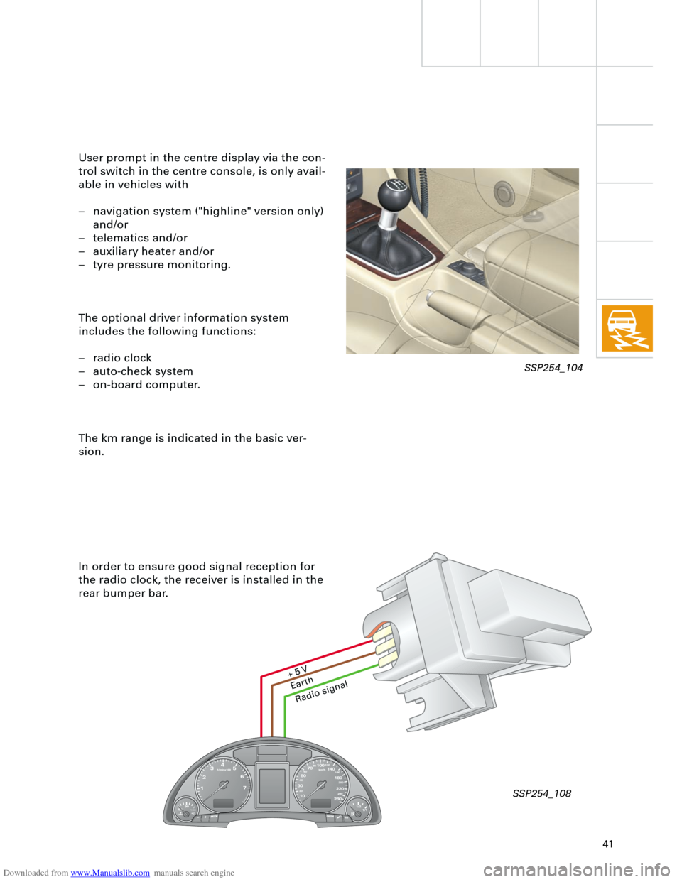
In order to ensure good signal reception for
the radio clock, the receiver is installed in the
rear bumper bar. User prompt in the centre display via the con-
trol switch in the centre console, is only avail-
able in vehicles with
– navigation system ("highline" version only)
and/or
– telematics and/or
– auxiliary heater and/or
– tyre pressure monitoring.
The optional driver information system
includes the following functions:
– radio clock
– auto-check system
– on-board computer.
The km range is indicated in the basic ver-
sion.
Ear
th
Radio signal
+ 5
V
SSP254_104
SSP254_108
Page 46 of 88
Downloaded from www.Manualslib.com manuals search engine
46
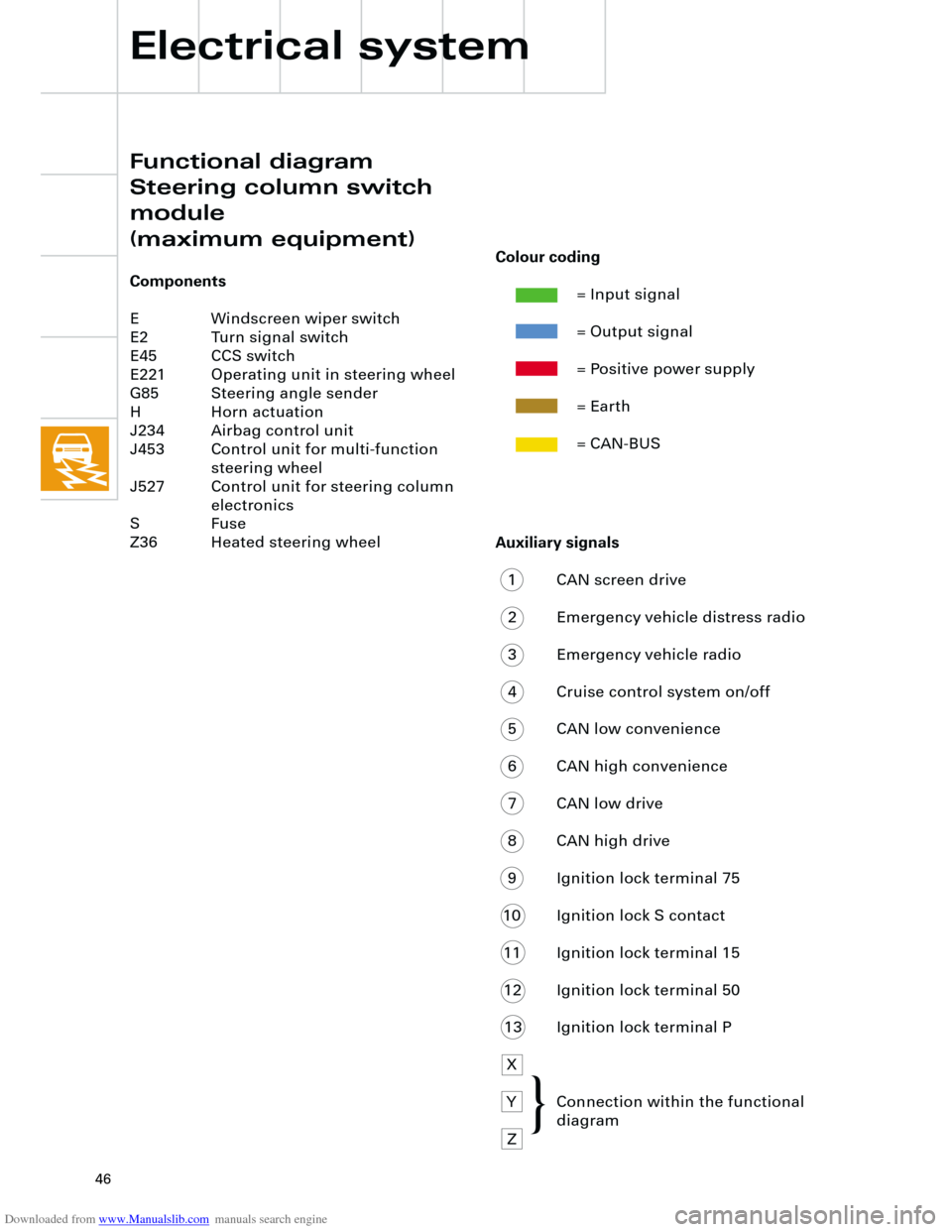
Auxiliary signals
1 CAN screen drive
2 Emergency vehicle distress radio
3 Emergency vehicle radio
4 Cruise control system on/off
5 CAN low convenience
6 CAN high convenience
7 CAN low drive
8 CAN high drive
9 Ignition lock terminal 75
10 Ignition lock S contact
11 Ignition lock terminal 15
12 Ignition lock terminal 50
13 Ignition lock terminal P
X
Y Connection within the functional
diagram
Z
Electrical system
Functional diagram
Steering column switch
module
(maximum equipment)
Components
E Windscreen wiper switch
E2 Turn signal switch
E45 CCS switch
E221 Operating unit in steering wheel
G85 Steering angle sender
H Horn actuation
J234 Airbag control unit
J453 Control unit for multi-function
steering wheel
J527 Control unit for steering column
electronics
S Fuse
Z36 Heated steering wheel
Colour coding
= Input signal
= Output signal
= Positive power supply
= Earth
= CAN-BUS
{
Page 58 of 88
Downloaded from www.Manualslib.com manuals search engine
58
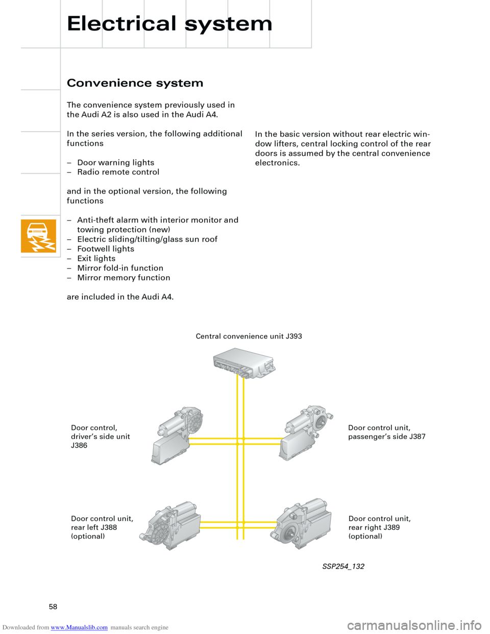
In the basic version without rear electric win-
dow lifters, central locking control of the rear
doors is assumed by the central convenience
electronics.
Convenience system
The convenience system previously used in
the Audi A2 is also used in the Audi A4.
In the series version, the following additional
functions
– Door warning lights
– Radio remote control
and in the optional version, the following
functions
– Anti-theft alarm with interior monitor and
towing protection (new)
– Electric sliding/tilting/glass sun roof
– Footwell lights
– Exit lights
– Mirror fold-in function
– Mirror memory function
are included in the Audi A4.
Electrical system
Central convenience unit J393
Door control unit,
passenger’s side J387 Door control,
driver’s side unit
J386
Door control unit,
rear right J389
(optional) Door control unit,
rear left J388
(optional)
SSP254_132
Page 62 of 88
Downloaded from www.Manualslib.com manuals search engine
62
TS
Electrical system
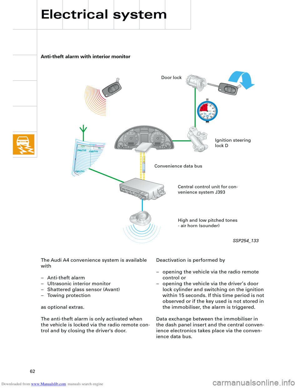
The Audi A4 convenience system is available
with
– Anti-theft alarm
– Ultrasonic interior monitor
– Shattered glass sensor (Avant)
– Towing protection
as optional extras.
The anti-theft alarm is only activated when
the vehicle is locked via the radio remote con-
trol and by closing the driver's door.Deactivation is performed by
– opening the vehicle via the radio remote
control or
– opening the vehicle via the driver’s door
lock cylinder and switching on the ignition
within 15 seconds. If this time period is not
observed or if the key used is not stored in
the immobiliser, the alarm is triggered.
Data exchange between the immobiliser in
the dash panel insert and the central conven-
ience electronics takes place via the conven-
ience data bus.
Anti-theft alarm with interior monitor
High and low pitched tones
- air horn (sounder) Central control unit for con-
venience system J393Ignition steering
lock D Door lock
Convenience data bus
SSP254_133
Page 65 of 88
Downloaded from www.Manualslib.com manuals search engine
65
Radio chorus II, concert II and symphony II
In the new Audi A4, the new generation of
radios, chorus II, concert II and symphony II
are available as options.
The following functions have been optimised:
– AM has been extended to include long
wave.
– There are now 12 programmable stations
for AM and FM.
All three radio versions are compatible with
the external CD changer (optional).
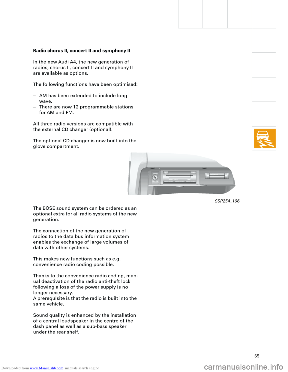
The optional CD changer is now built into the
glove compartment.
The BOSE sound system can be ordered as an
optional extra for all radio systems of the new
generation.
The connection of the new generation of
radios to the data bus information system
enables the exchange of large volumes of
data with other systems.
This makes new functions such as e.g.
convenience radio coding possible.
Thanks to the convenience radio coding, man-
ual deactivation of the radio anti-theft lock
following a loss of the power supply is no
longer necessary.
A prerequisite is that the radio is built into the
same vehicle.
Sound quality is enhanced by the installation
of a central loudspeaker in the centre of the
dash panel as well as a sub-bass speaker
under the rear shelf.
AIRBAG
OFFON
Audicd chargerCOMPAKTAKTDIGITAL AUDIOAL AUDIO
LOAD
SSP254_106
Page 66 of 88
Downloaded from www.Manualslib.com manuals search engine
66
In order to improve sound quality, acoustic
curves related to vehicle type are stored in the
concert II and symphony II radios.
The acoustic curves are set in the control unit
coding function of the radio systems.
In addition, the sound settings for the FM, AM
and CD modes are stored separately in the
concert II and symphony II radios. Conse-
quently, the various level controls do not
require resetting each time the driver
changes modes.
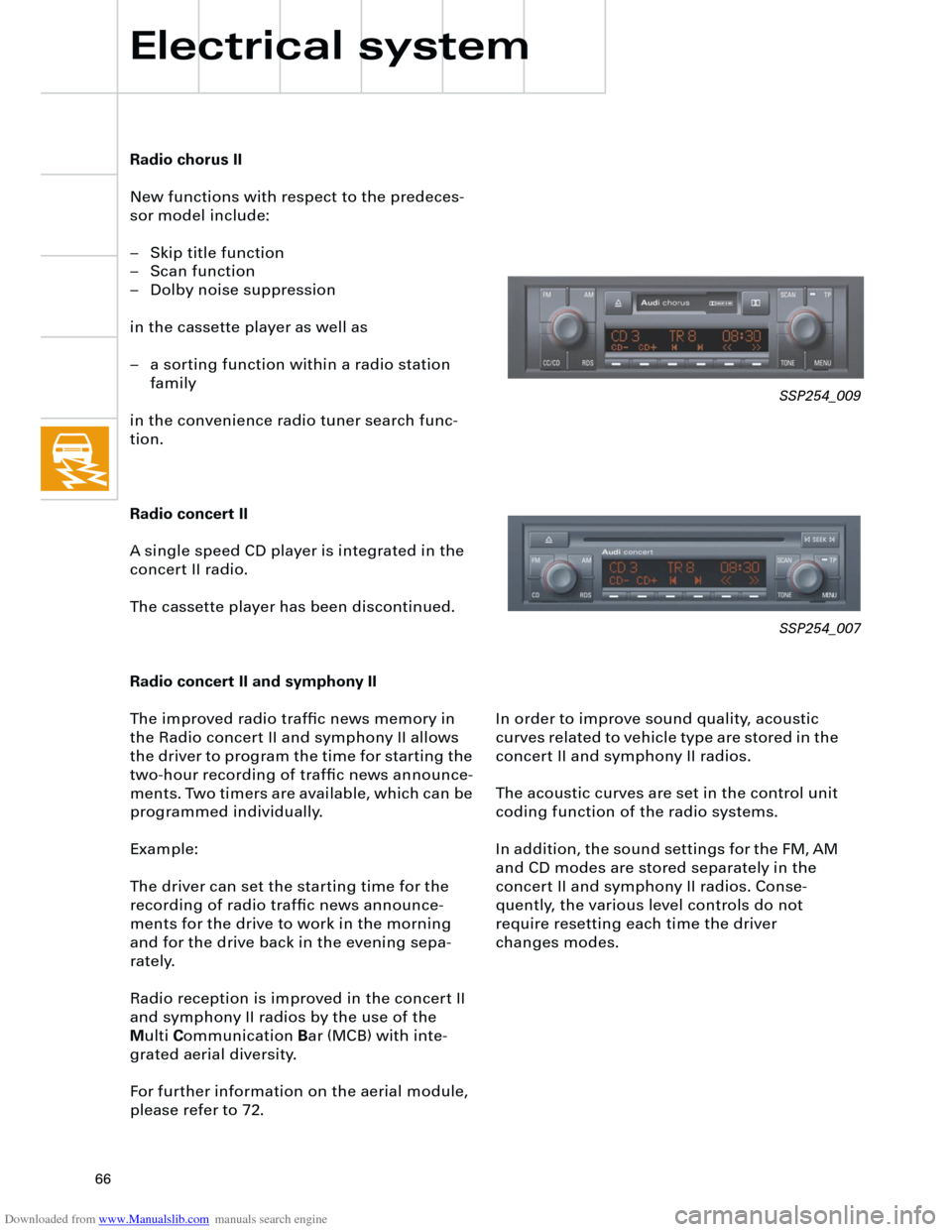
Radio chorus II
New functions with respect to the predeces-
sor model include:
– Skip title function
– Scan function
– Dolby noise suppression
in the cassette player as well as
– a sorting function within a radio station
family
in the convenience radio tuner search func-
tion.
Radio concert II
A single speed CD player is integrated in the
concert II radio.
The cassette player has been discontinued.
Radio concert II and symphony II
The improved radio traffic news memory in
the Radio concert II and symphony II allows
the driver to program the time for starting the
two-hour recording of traffic news announce-
ments. Two timers are available, which can be
programmed individually.
Example:
The driver can set the starting time for the
recording of radio traffic news announce-
ments for the drive to work in the morning
and for the drive back in the evening sepa-
rately.
Radio reception is improved in the concert II
and symphony II radios by the use of the
M
ulti
C
ommunication
B
ar (MCB) with inte-
grated aerial diversity.
For further information on the aerial module,
please refer to 72.
Electrical system
SSP254_009
SSP254_007
Page 67 of 88
Downloaded from www.Manualslib.com manuals search engine
67
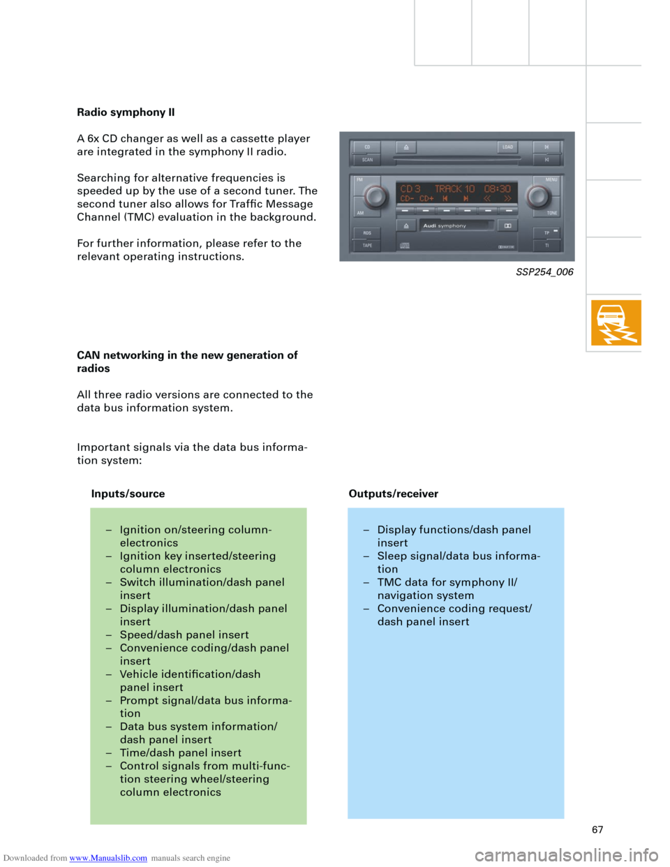
Radio symphony II
A 6x CD changer as well as a cassette player
are integrated in the symphony II radio.
Searching for alternative frequencies is
speeded up by the use of a second tuner. The
second tuner also allows for Traffic Message
Channel (TMC) evaluation in the background.
For further information, please refer to the
relevant operating instructions.
CAN networking in the new generation of
radios
All three radio versions are connected to the
data bus information system.
Important signals via the data bus informa-
tion system:
SSP254_006
– Ignition on/steering column-
electronics
– Ignition key inserted/steering
column electronics
– Switch illumination/dash panel
insert
– Display illumination/dash panel
insert
– Speed/dash panel insert
– Convenience coding/dash panel
insert
– Vehicle identification/dash
panel insert
– Prompt signal/data bus informa-
tion
– Data bus system information/
dash panel insert
– Time/dash panel insert
– Control signals from multi-func-
tion steering wheel/steering
column electronics– Display functions/dash panel
insert
– Sleep signal/data bus informa-
tion
– TMC data for symphony II/
navigation system
– Convenience coding request/
dash panel insert
Inputs/sourceOutputs/receiver