technical data AUDI A4 2008 B8 / 4.G Owners Manual
[x] Cancel search | Manufacturer: AUDI, Model Year: 2008, Model line: A4, Model: AUDI A4 2008 B8 / 4.GPages: 342, PDF Size: 13.14 MB
Page 309 of 342
Fuses and bulbs307
Controls
Safety
Driving tips
General maintenance
Self-help
Technical data
– Take the screwdriver and the interchangeable Torx socket
out of the vehicle tool kit.
– Remove the screws ⇒page 306, fig. 288 that secure the
trim panel to the lock carrier and detach the trim panel.
– Slacken the two screws that secure the headlight to the
lock carrier and the two screws at the underside of the
headlight (the screws at the underside should not be
slackened more than five turns) ⇒page 306, fig. 289.
– Carefully pull the headlight forward about 60 mm.
– Release and unplug the electrical connector.
– Carefully take the headlight out towards the front (swivel
it slightly if necessary).
Installing
– Perform all of the above steps in reverse sequence.The headlight must be inserted in two guides (on the underside of
the headlight). This is the only way to ensure that the headlight is
installed in the correct position. To determine whether the headlight
is correctly installed, check that it is aligned flush with adjacent
body parts (such as the wing panel).
Do not interchange the securing screws.
Caution
Please take particular care not to damage or scratch the adjacent
parts of the body when removing or installing the headlights.
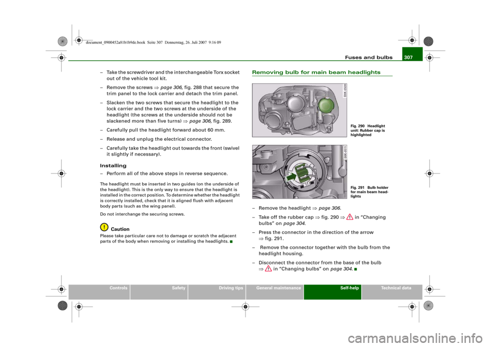
Removing bulb for main beam headlights– Remove the headlight ⇒page 306.
– Take off the rubber cap ⇒fig. 290 ⇒ in “Changing
bulbs” on page 304.
– Press the connector in the direction of the arrow
⇒fig. 291.
– Remove the connector together with the bulb from the
headlight housing.
– Disconnect the connector from the base of the bulb
⇒ in “Changing bulbs” on page 304.
Fig. 290 Headlight
unit: Rubber cap is
highlightedFig. 291 Bulb holder
for main beam head-
lights
document_0900452a81b1b9de.book Seite 307 Donnerstag, 26. Juli 2007 9:16 09
Page 311 of 342
Fuses and bulbs309
Controls
Safety
Driving tips
General maintenance
Self-help
Technical data
– Remove the headlight ⇒page 306.
– Take off the cover ⇒page 308, fig. 294 ⇒ in
“Changing bulbs” on page 304.
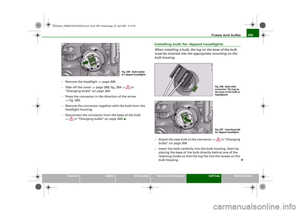
– Press the connector in the direction of the arrow
⇒fig. 295.
– Remove the connector together with the bulb from the
headlight housing.
– Disconnect the connector from the base of the bulb
⇒ in “Changing bulbs” on page 304.
Installing bulb for dipped headlights
When installing a bulb, the lug on the base of the bulb
must be inserted into the appropriate mounting on the
bulb housing.– Attach the new bulb to the connector ⇒ in “Changing
bulbs” on page 304.
– Insert the bulb carefully into the bulb housing. Start by
placing the base of the bulb directly behind one of the
retaining hooks so that the lug fits into the recess on the
bulb housing.
Fig. 295 Bulb holder
for dipped headlights
Fig. 296 Bulb with
connector: The lug on
the base of the bulb is
highlightedFig. 297 Inserting bulb
for dipped headlights
document_0900452a81b1b9de.book Seite 309 Donnerstag, 26. Juli 2007 9:16 09
Page 313 of 342
Fuses and bulbs311
Controls
Safety
Driving tips
General maintenance
Self-help
Technical data
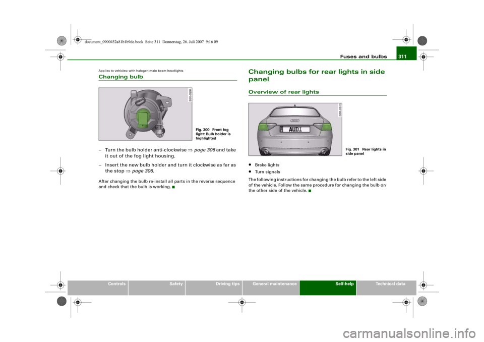
Applies to vehicles: with halogen main beam headlightsChanging bulb– Turn the bulb holder anti-clockwise ⇒page 306 and take
it out of the fog light housing.
– Insert the new bulb holder and turn it clockwise as far as
the stop ⇒page 306.After changing the bulb re-install all parts in the reverse sequence
and check that the bulb is working.
Changing bulbs for rear lights in side
panelOverview of rear lights•
Brake lights
•
Turn signals
The following instructions for changing the bulb refer to the left side
of the vehicle. Follow the same procedure for changing the bulb on
the other side of the vehicle.
Fig. 300 Front fog
light: Bulb holder is
highlighted
Fig. 301 Rear lights in
side panel
document_0900452a81b1b9de.book Seite 311 Donnerstag, 26. Juli 2007 9:16 09
Page 315 of 342
Fuses and bulbs313
Controls
Safety
Driving tips
General maintenance
Self-help
Technical data
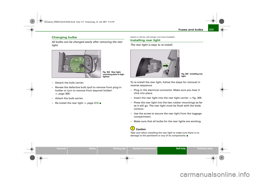
Changing bulbs
All bulbs can be changed easily after removing the rear
light.– Detach the bulb carrier.
– Renew the defective bulb (pull to remove from plug-in
holder or turn to remove from bayonet holder)
⇒page 305.
– Attach the bulb carrier.
– Re-install the rear light ⇒page 313.
Applies to vehicles: with halogen main beam headlightsInstalling rear light
The rear light is easy to re-install.To re-install the rear light, follow the steps for removal in
reverse sequence.
– Plug in the electrical connector. Make sure you hear it
click into place.
– Insert the rear light into the rear light carrier ⇒fig. 305.
– Press the rear light into the two rubber mountings as far
as it will go. The rear light must be flush with the body
contour.
– Use the screw to secure the rear light from the luggage
compartment.
– Make sure that all bulbs for the rear lights are working.
CautionTake care when installing the rear light to make sure there is no
damage to the paintwork or any of its components.
Fig. 304 Rear light,
mounting plate is high-
lighted
Fig. 305 Installing rear
light
document_0900452a81b1b9de.book Seite 313 Donnerstag, 26. Juli 2007 9:16 09
Page 317 of 342
Fuses and bulbs315
Controls
Safety
Driving tips
General maintenance
Self-help
Technical data
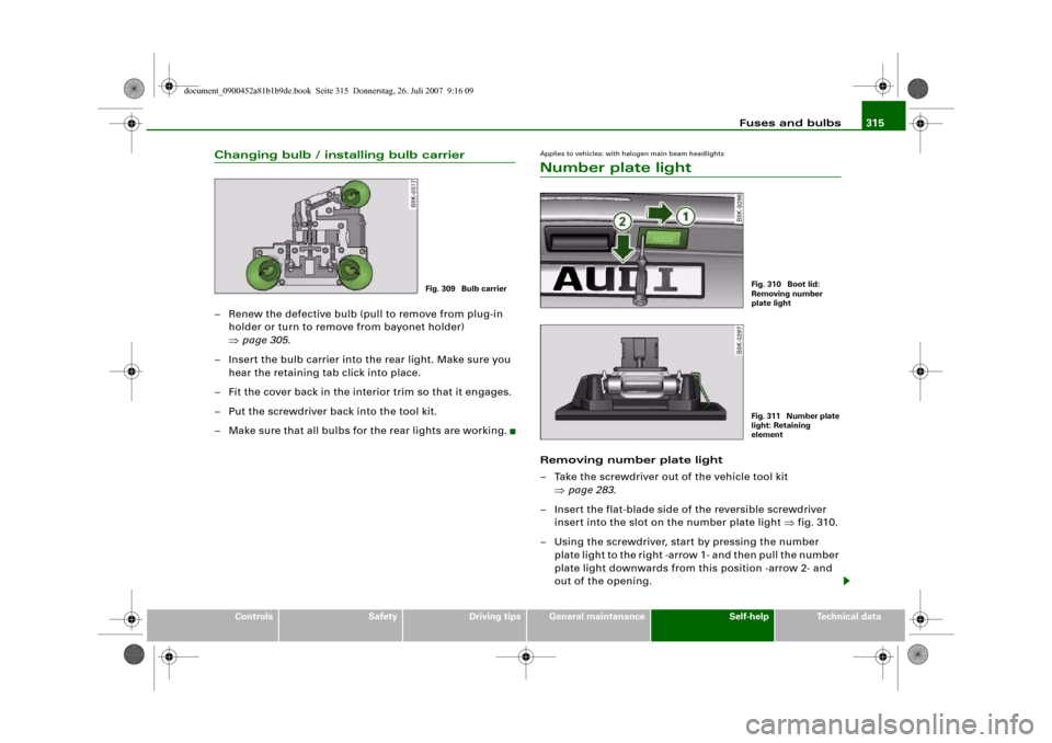
Changing bulb / installing bulb carrier– Renew the defective bulb (pull to remove from plug-in
holder or turn to remove from bayonet holder)
⇒page 305.
– Insert the bulb carrier into the rear light. Make sure you
hear the retaining tab click into place.
– Fit the cover back in the interior trim so that it engages.
– Put the screwdriver back into the tool kit.
– Make sure that all bulbs for the rear lights are working.
Applies to vehicles: with halogen main beam headlightsNumber plate lightRemoving number plate light
– Take the screwdriver out of the vehicle tool kit
⇒page 283.
– Insert the flat-blade side of the reversible screwdriver
insert into the slot on the number plate light ⇒fig. 310.
– Using the screwdriver, start by pressing the number
plate light to the right -arrow 1- and then pull the number
plate light downwards from this position -arrow 2- and
out of the opening.
Fig. 309 Bulb carrier
Fig. 310 Boot lid:
Removing number
plate lightFig. 311 Number plate
light: Retaining
element
document_0900452a81b1b9de.book Seite 315 Donnerstag, 26. Juli 2007 9:16 09
Page 319 of 342
Fuses and bulbs317
Controls
Safety
Driving tips
General maintenance
Self-help
Technical data
document_0900452a81b1b9de.book Seite 317 Donnerstag, 26. Juli 2007 9:16 09
Page 321 of 342
319 Technical data
document_0900452a81b1b9de.book Seite 319 Donnerstag, 26. Juli 2007 9:16 09
Page 322 of 342
General notes 320General notesExplanation of technical dataWhere not otherwise indicated or separately listed, all technical
data apply to vehicles with standard equipment for the German
market. Other figures may apply for special versions and export
models.
Please note that the details listed in the vehicle's registration docu-
ments can be taken as correct.
Engine data
The figures for engine power output are determined according to
EU standards.
Performance figures
The performance figures were measured without equipment which
may influence performance, such as mudflaps or extremely wide-
section tyres.
Kerb weight (unladen weight)
These figures (kerb weight according to the currently applicable
version of EU Directive 92/21/EEC) apply to the vehicle with the tank
90% full, with no special equipment. The figures include an addi-
tional 75 kg to allow for the weight of the driver.
When towing a trailer, the gross vehicle weight may be exceeded by
up to 30 kg and the maximum rear axle weight may be exceeded by
up to 80 kg.
Maximum trailer weights
The maximum trailer weights are calculated in accordance with the
currently applicable version of EU Directive 92/21/EEC.
The figures for a trailer with brakes, on gradients up to 8% are appli-
cable only up to a maximum speed of 80 km/h (even though higher
speeds may be permitted when towing a trailer in some countries).The figures for a trailer with brakes on gradients up to 12% and for
the weight of car and trailer on gradients up to 12% are applicable
up to a maximum speed of 100 km/h. This maximum speed must not
be exceeded even in countries where higher speeds are permitted.
Maximum draw bar loading
The vertical load exerted by the trailer drawbar on the ball joint of
the towing bracket must not exceed 80 kg.
In the interest of safety, we recommend applying the maximum
permitted draw bar weight. The stability of the trailer could be
adversely affected if too little weight is applied.
If the maximum permitted drawbar weight cannot be obtained, e.g.
when using small or light trailers, statutory regulations require that
the drawbar weight be at least 4% of the actual trailer weight (for
single-axle trailers or twin-axle trailers with an axle spacing less
than 1.0 m).
Dimensions1) The height of the vehicle depends on the tyres and suspension.
Take care not to damage low-mounted parts of the car (such as the
spoiler or exhaust system) on steep ramps, uneven road surfaces or
roadside kerbs, etc.
This applies especially when the vehicle is fully laden.Length
mm
4703
Width
mm
1826
Width across mirrors
mm
1953
Height, unladen
1)
mm
1417-1437
document_0900452a81b1b9de.book Seite 320 Donnerstag, 26. Juli 2007 9:16 09
Page 323 of 342
General notes321
Controls
Safety
Driving tips
General maintenance
Self-help
Technical data
CapacitiesFuel tank
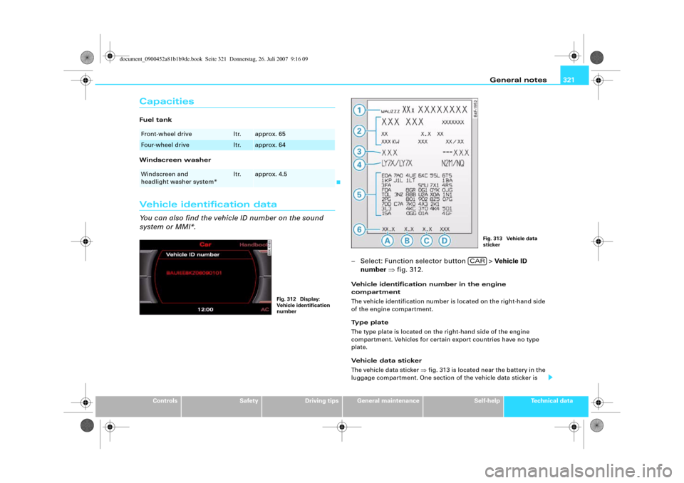
Windscreen washerVehicle identification dataYou can also find the vehicle ID number on the sound
system or MMI*.
– Select: Function selector button > Vehicle ID
number ⇒fig. 312.Vehicle identification number in the engine
compartment
The vehicle identification number is located on the right-hand side
of the engine compartment.
Type plate
The type plate is located on the right-hand side of the engine
compartment. Vehicles for certain export countries have no type
plate.
Vehicle data sticker
The vehicle data sticker ⇒fig. 313 is located near the battery in the
luggage compartment. One section of the vehicle data sticker is
Front-wheel drive
ltr.
approx. 65
Four-wheel drive
ltr.
approx. 64
Windscreen and
headlight washer system*
ltr.
approx. 4.5
Fig. 312 Display:
Vehicle identification
number
Fig. 313 Vehicle data
sticker
CAR
document_0900452a81b1b9de.book Seite 321 Donnerstag, 26. Juli 2007 9:16 09
Page 325 of 342
Performance, weights and dimensions323
Controls
Safety
Driving tips
General maintenance
Self-help
Technical data
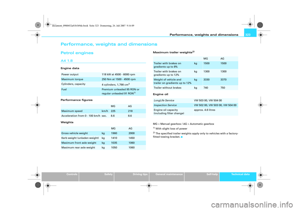
Performance, weights and dimensionsPetrol enginesA4 1.8Engine data
Performance figures
WeightsMaximum trailer weights
2)
Engine oil
MG = Manual gearbox / AG = Automatic gearbox1) With slight loss of power2) The specified trailer weights apply only to vehicles with a factory-
fitted towing bracket.
Power output
118 kW at 4500 - 6000 rpm
Maximum torque
250 Nm at 1500 - 4500 rpm
Cylinders, capacity
4 cylinders, 1,798 cm
3
Fuel
Premium unleaded 95 RON or
regular unleaded 91 RON
1)
MG
AG
Maximum speed
km/h
225
218
Acceleration from 0 - 100 km/h
sec.
8.6
8.6
MG
AG
Gross vehicle weight
kg
1960
2000
Kerb weight (unladen weight)
kg
1410
1450
Maximum front axle weight
kg
1035
1060
Maximum rear axle weight
kg
1050
1060
MG
AG
Trailer with brakes on
gradients up to 8%
kg
1500
1500
Trailer with brakes on
gradients up to 12%
kg
1300
1300
Weight of vehicle and
trailer on gradients up to 12%
kg
3330
3370
Trailer without brakes
kg
740
750
LongLife Service
VW 503 00, VW 504 00
Inspection Service
VW 502 00, VW 503 00, VW 504 00
Engine oil capacity
(including filter change)
approx. 4.6 litres
document_0900452a81b1b9de.book Seite 323 Donnerstag, 26. Juli 2007 9:16 09