reset AUDI A4 2013 Owners Manual
[x] Cancel search | Manufacturer: AUDI, Model Year: 2013, Model line: A4, Model: AUDI A4 2013Pages: 302, PDF Size: 75.61 MB
Page 11 of 302
CD
@
®
©
®
®
(j)
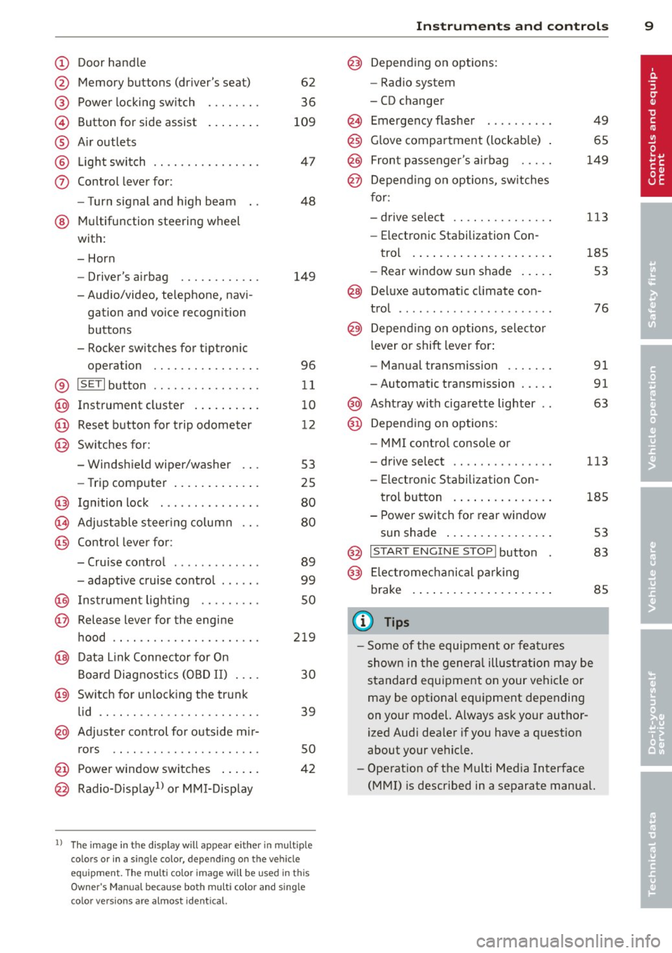
Door handle
Memory buttons (dr iver's seat)
Power locking sw itch
Button for side ass ist
A ir outlets
L ight switch
Control lever for :
- T urn signal and high beam
@ Multifunction steering wheel
with:
- Horn
- Driver's airbag
- Audio/video, telephone, navi-
gation and vo ice recognition
buttons
- Rocker switches for tiptron ic
opera tion ........... .... .
® ISET I button ...... ..... .... .
@ Instrument cluster .. ... .. .. .
@ Reset button for trip odometer
@ Sw itches for:
- Windsh ield wiper/washer
- Trip computer ..... ... .. .. .
@ Ignition lock ............. . .
(8) Adjustable s teer ing column
@ Control lever for :
- Cruise contro l ......... ... .
- adaptive cruise contro l .... . .
@ Ins trumen t lighting .... .. .. .
@ Release lever for the engine
hood .. .. .. .. ........... .. .
@ Data L ink Connector for On
B oard Diag nostics (OBD II) . .. .
@ Sw itch for unlock ing the trunk
lid .. .. .. ................. .
@ Adjuster control fo r outside m ir-
r ors .. .. .. .. ........... .. .
@ Power window switches ... .. .
@ Rad io-Display1l or MMI-Display
62
36
109
4 7
48
149
96
11
10
12
53
25
80
80
89
99
so
219
30
39
50
42
l) T he image in t he d is pl ay will app ear e it h er in mu lt iple
c o lor s or in a singl e co lor , de pen din g o n th e vehicl e
e q ui pment. T he m ulti co lo r im age w ill b e used i n this
O w ner's M anual becau se bo th mu lt i co lo r and si ng le
c o lor ver sio ns are almos t ide ntic al.
In strument s and control s 9
@) Depend ing on options:
- Rad io system
- CD changer
Emergency flashe r
G love compartment (lockab le)
Front passenger's airbag .....
Depend ing o n op tions, sw itches
f or: 49
65
149
- drive select .. .. .......... .
113
- Electronic Stabilization Con-
trol . ... .. .. .. . .. ... .... .
- Rear window sun shade .. .. . 185
53
@ Deluxe automat ic cl imate con-
trol ...... .. .... .......... .
@) Depending on options, selecto r
lever or shift lever for :
- Manual transmission ...... .
- Automatic transmission .... .
@ Asht ray with ciga rette lighter
@ Depend ing on options:
- MMI contro l console or
76
91
91
63
- drive select . . . . . . . . . . . . . . . 113
- Electronic Stabilizat ion Con-
trol button . . . . . . . . . . . . . . . 185
- Power switch for rear window sun shade . . . . . . . . . . . . . . . . 53
@ I STA RT ENGI NE STOPI button 83
@) Electromec hanical p arking
brake . . . . . . . . . . . . . . . . . . . . . 85
(D Tips
-Some of the equipment o r fea tures
show n in the gener al illustration m ay be
standard equ ipment on your vehicle or
may be optional eq uipment depending
on your model. Always as k your author
ized Aud i dea ler if you have a quest ion
about your ve hicle.
- Operat ion of the Multi Med ia Interface
(MMI) is described in a separate manua l.
Page 12 of 302
10 Instruments and warning/indicator lights
Instruments and warning/indicator Lights
Instruments
Instrument cluster and controls
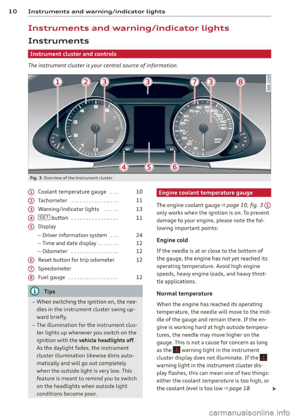
The instrument cluster is your central source of information.
Fig. 3 Ove rv iew of the instrument cluster
CD Coolant temperature gauge .. .
@ Tachometer ........... .. .. .
@ Warning/indicator lights .. .. .
© ISETlbutton .... .... .. .... . .
® Display
- Driver information system .. .
- Time and date d isplay .. .. .. .
- Odometer .......... ... .. .
@ Reset button for trip odometer
(z) Speedometer
@ Fuel gauge . .... ..... .. .. .. .
(D Tips
10
11
13
11
24
12
12
12
12
- When switching the ignition on, the nee
dles in the instrument cluster swing up
ward briefly.
- The illumination for the instrument clus
ter lights up whenever you switch on the
i gnition with the
vehicle headlights off .
As the daylight fades, the instrument
cluster illumination likewise dims auto
matically a nd will go out completely
when the outside light is
very low. This
feature is meant to remind you to switch
on the headlights when outside light
conditions become poor .
Engine coolant temperature gauge
The engine coolant gauge q page 10, fig. 3 CD
only works when the ignition is on. To prevent
damage to your engine, please note the fol
lowing important points:
Engine cold
If the needle is at or close to the bottom of
the gauge, the engine has not yet reached its
operating temperature. Avoid high engine
speeds, heavy engine loads, and heavy throt
tle app lications.
Normal temperature
When the engine has reached its operating
temperature, the needle will
move to the mid
dle of the gauge and remain there . If the en
gine is working hard at high outs ide tempera
tures, the needle may
move higher on the
gauge. This is not a cause for concern as long
as the . warning light in the instrument
cluster display does not illuminate. If the.
warning light in the instrument cluster dis
play flashes, this can mean one of two things:
either the coolant
temperature is too high, or
the coolant
level is too low q page 18 Ill-
Page 14 of 302
12 Instruments and warning/indicator lights
disabled. It is also important to notify your in
surance company about the loss .
Setting the speed warning
By pressing the I SETI button br iefly, you can
set threshold 1 of the speed warning while
you are dr iv ing
~ page 88. By mainta ining
pressure on the ISETI button, you de lete the
warning threshold.
Digital clock with date display and
Odometer
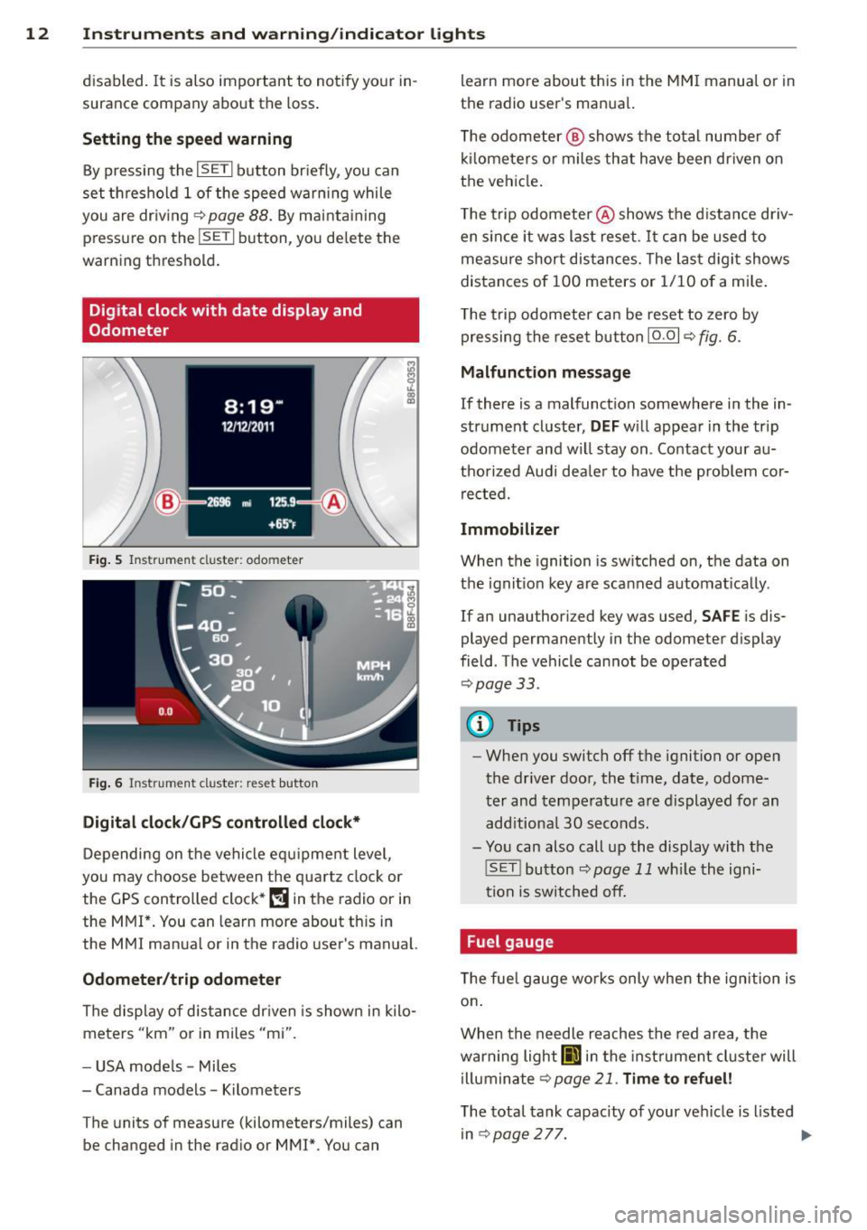
Fig. 5 Instrument cl uster: odo meter
Fig. 6 Instrum ent cl uster : re se t button
Digital clock/GPS controlled clock*
Depending on the vehicle equ ipment level,
you may choose between the quartz clock or
the
GPS controlled clock* (!j in the radio or in
the MMI*. You can learn more about th is in
the MMI manual or in the radio user's manual.
Odometer /trip odometer
The display of distance dr iven is shown in kilo
meters "km" or in miles "mi".
- USA mode ls - Miles
- Canada models - Kilometers
T he units of measure (kilometers/miles) can
be changed in the radio or
MMI*. You can learn more about this in the MM
I manual or in
the radio user's manual.
T he odometer @ shows the total number of
kilometers or miles that have been driven on
the vehicle .
The trip odometer @shows the distance driv
en since it was last reset .
It can be used to
measure short distances. The last digit shows
distances of
100 meters or 1/10 of a mile.
T he trip odometer can be reset to zero by
pressing the reset button IO .OI
~ fig. 6.
Malfunction message
If there is a malfunction somewhere in the in
strument cluster,
DEF will appear in the trip
odometer and w il l stay on . Contact your au
thorized Audi dea le r to have the prob lem cor
rected.
Immobilizer
When the ignition is switched on, the data on
t h e ignition key are scanned automat ically .
If an unauthor iz ed key was used,
SAFE is dis
played permanently in the odometer display
field . The vehicle cannot be operated
~ page 33.
(D Tips
-When you switch off the ignition or open
the-driver door, the t ime, date, odome
ter and temperature are displayed for an
add itiona l
30 seconds.
- You can also call up the display with the
! SET !button
~page 11 while the igni
tion is switched off.
· Fuel gauge
T he fue l gauge works only when the ignition is
on .
When the needle reaches the red area, the
warning light
Ii] in the instr ument cluster will
illuminate
Qpage 21. Time to refuel!
The total tank capacity of your vehicle is listed
in~page277. .,,.
Page 26 of 302
24 Driver information d isplay
Driver information
display
Introduction
The Driver information display inside the in
strument cluster provides you, the driver ,
with important information.
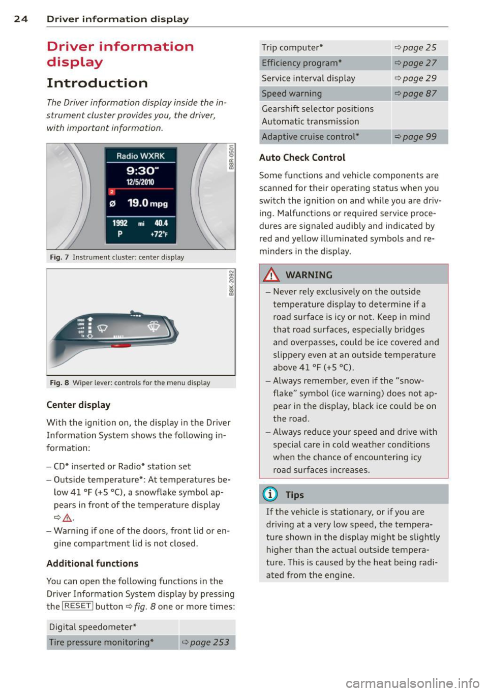
Fig. 7 Ins trum en t cl uster : ce nter display
Fig. 8 W iper lev er: con trols fo r th e menu disp lay
Center display
W ith the ignition on, the display in the Dr iver
I nformation System shows the following in
formation :
- CD* inserted or Radio* station set
- Outside temperature* : At temperatures be-
low 41 °F (+5 °C), a snowflake symbol ap
pears in front of the temperature display
c::> .&_.
-Warning if one of the doors, front lid or en-
gine compartment lid is not closed .
Additional functions
You can open the following functions in the
Driver Information System display by pressing
the
! RESET I button c::> fig. 8 one or more times:
Digital speedometer*
Tire pressure monitoring *
~page253
Trip computer*
Efficiency program*
Service interval display
c::>page25
c::> page 27
c::> page 29
--·-
Gearshift selector positions
Automatic transmission
Adaptive cruise control*
Auto Check Control
<::>page 87
Some functions and vehicle components are
scanned for their operating status when you
switch the ignition on and whi le you are driv
ing. Malfunctions or required service proce
dures are signaled audibly and indicated by
red and yellow illuminated symbols and re
minders in the d isplay.
A WARNING
--- Never rely exclusively on the outside
temperature display to determine if a
road surface is icy or not. Keep in mind
that road surfaces, especially br idges
and overpasses, could be ice covered and
slippery even at an outside temperature
above 41 °F (+5 °C).
- Always remember, even if the "snow
flake" symbol (ice warning) does not ap
pear in the disp lay, black ice cou ld be on
the road.
- Always reduce your speed and drive with
specia l care in cold weather cond itions
when the chance of encountering icy
road surfaces increases.
¢j) Tips
If the vehicle is stationary, or if you are
driving at a very low speed, the tempera
ture shown in the display might be s light ly
higher than the actual outs ide tempera
ture. This i.s caused by the heat being radi
ated from the engine .
Page 27 of 302
Trip computer
Introduction
Applies to vehicles: with trip computer
The trip computer gives you information on
current and average fuel mileage, average
speed, fuel range and driving time .
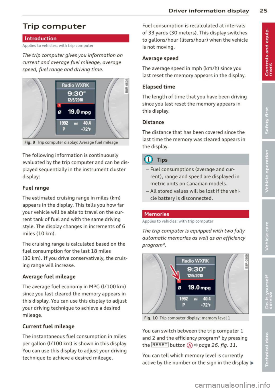
Fig. 9 Trip comp uter d isp lay : Ave rage fuel mileage
The following information is continuously
eva luated by the trip computer and can be dis
played sequentia lly in the instrument cluster
disp lay:
Fuel range
The estimated cruising range in miles (km)
appears in the display. This tells you how far
your vehicle wi ll be able to travel on the cur
rent tank of fuel and with the same driving
style. The display changes in increments of 6
miles (10 km).
The cruising range is calcu lated based on the
fuel consumption for the last 18 miles
(30 km). If you drive conservatively, the cruis
ing range will increase.
Average fuel mileage
The average fuel economy in MPG (l/100 km)
since you last cleared the memory appears in
this display. You can use this disp lay to adjust
your driving technique to achieve a desired
mileage.
Current fuel mileage
The instantaneous fuel consumption in miles
per gallon (l/100 km) is shown in this disp lay.
You can use this display to adjust your driving
technique to achieve a desired mileage.
Driver information display 25
Fuel consumption is recalculated at intervals
of 33 yards (30 meters). This display switches
to gallons/hour (liters/hour) when the veh icle
is not moving .
Average speed
The average speed in mph (km/h) s ince you
last reset the memory appears in the display.
Elapsed time
The length of time that yo u have been driving
s inc e you last reset the memory appears in
this display.
Distance
The distance that has been covered since the
last time the memory was cleared appears in
the display.
(0 Tips
- Fuel consumptions (average and cur
rent), range and speed are displayed in
metric units on Canadian models.
- All stored values will be lost if the vehi
cle battery is disconnected.
Memories
App lies to vehicles: wi th trip computer
The trip computer is equipped with two fully
automatic memories as well as an efficiency
program*.
Fig. 10 T rip comput er dis play: memory lev el 1
You can switch between the trip computer 1
and 2 and the efficiency program* by pressing
the
I RESET I button @c::> page 26, fig. 11 .
You can tell which memory leve l is currently
active by the number or the sign in the display .,..
Page 28 of 302
26 Driver in formation d isplay
¢fig . 10 . The data from the single -trip mem
ory (memory leve l 1) is being displayed if a
D
appears in the display . If a II is shown, then
the data from the total -trip memory is being
d isplayed (memory leve l 2). The fuel pump
nozzle
iii indicates the efficiency program*
¢ page 27.
Single-tr ip m emory (Trip computer 1 )
The single-trip memory stores the trip infor
mat ion from the time the ignition is turned o n
until it is turned off. If the trip is continued
w ithin 2 hours from the t ime the ignition was
turned off, the new data will be included in
the calcu lation of the current trip i nfo rma
tion .
If the t rip is inte rrupted fo r more than 2
hours the memory is reset automati ca lly.
Total -trip memory (Trip computer 2)
Unlike the sing le-trip memory, the tota l- tr ip
memory is not reset automatically . Th is per
mits you to evaluate your d riving data for the
enti re pe riod be tween manual rese ts.
Efficiency program*
The effic iency program can help you to use
less fuel ¢
page 2 7.
Operation
App lies to vehicles: with trip computer
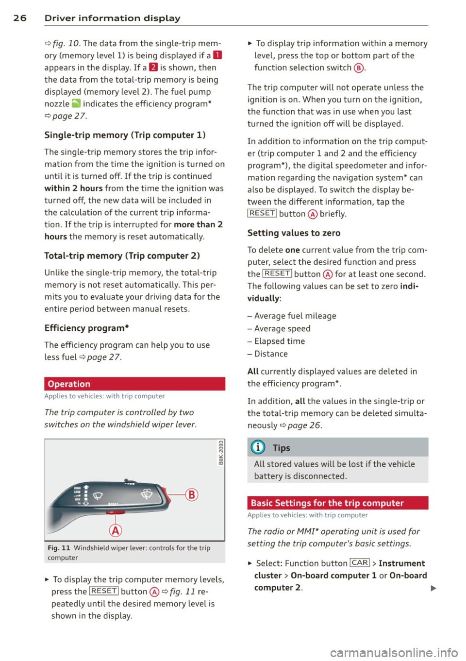
The trip computer is controlled by two
switches on the windshield wiper lever .
Fig. 11 W indsh ie ld wipe r leve r: co ntrols for the tri p
co mpute r
M
"' 0 N
"' co a:,
~ To d isp lay the trip computer memory levels ,
press the
I RES ET I button @¢ fig. 11 re
peatedly unt il the desired memory leve l is
shown in the d isplay .
~ To display tr ip in format ion wit hin a memory
level, press the top or bottom part of the
function se lection switch @.
T he trip computer will not ope rate un less the
ignition is on. W hen you t urn on the ignition,
the function that was in use when you last
turned the ignition off will be displayed .
In add ition to info rmation on the trip comput
er (trip computer 1 and 2 and the efficiency
program *), t he digital spee dometer and infor
mation regard ing the nav igat ion system* can
also be displayed. To switch the d isp lay be
tween the different information, tap the
I RESET ! button@ briefly.
Sett ing values to zero
To de lete one current va lue from the trip com
puter, se lect the des ired funct ion and press
t h e
I RES ET I button @for at least one second.
The following values can be set to zero
indi
vidually :
- Average fue l mi leage
- Average speed
- Elapsed t ime
- Dis tance
All cur rently d isplayed va lues are deleted in
the eff iciency program*.
In add it ion,
all the values in the single-trip or
the total-tr ip memory can be de leted simulta
neously ¢
page 26.
(D Tips
All stored va lues w ill be lost if the veh icle
battery is discon nected .
Basic Settings for the trip computer
Applies to vehicles: with trip computer
The radio or MMI* operating unit is used for
setting the trip computer's basic settings.
~ Select: Function b utton ICAR ! > Instrument
cluster > On -board computer 1 or On-board
computer 2 . .,.
Page 29 of 302
The values in the single-trip or the total-trip
memory can a ll be reset to zero at the same
time under
Re set in the menu .
I n addition, you can determine what informa
tion from the trip computer should be shown in the instrument cluster display. If one of the
p ieces of driver information is turned
Off , that
driver information w ill not be shown in the
display. The information will con tinue to be
calculated by the trip computer and can be
turned back
On at any t ime .
(D Tips
-This function is not avai lab le on all
vehicles.
- The driving information in the efficiency
program is also reset to zero with the
s ingle-trip memory .
Gearshift Indicator
Appl ies to vehicles: with manu al transmis sion a nd gea r·
shi ft indica tor
This indica tor con help conserve fuel.
~~~------------~~ ~.;;-
Fig. 12 Disp lay : Gea rs hi ft indicator
m ~ ~ a, a,
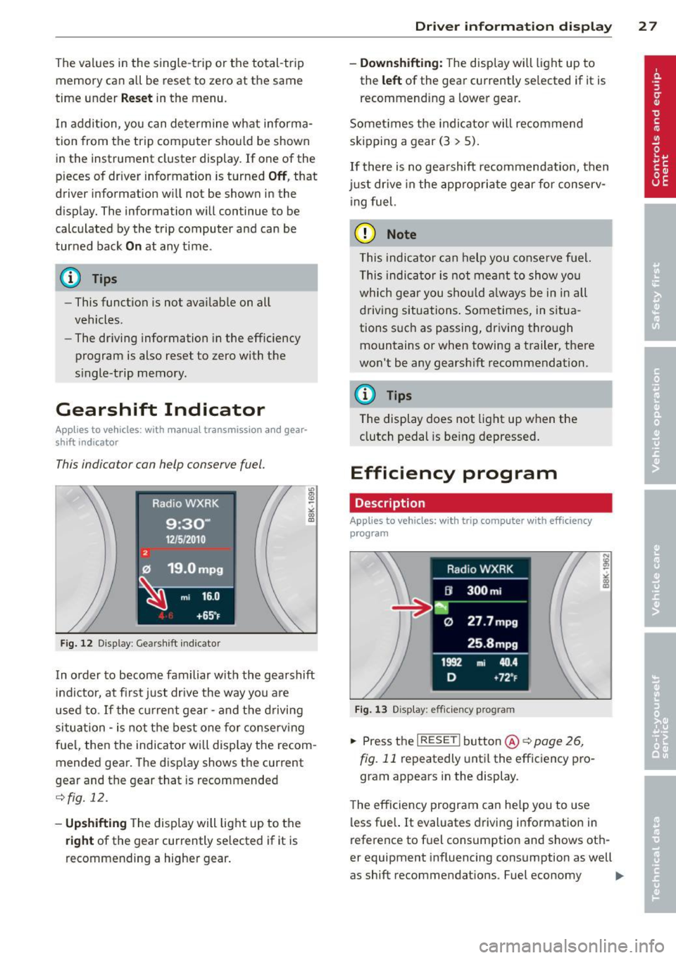
In order to become familiar with the gearshift
indictor, at first just drive the way you are
used to.
If the current gear -and the d riving
situa tion -is not the best one for conse rv ing
fuel, then the indicator will display the recom
mended gear. The disp lay shows the current
gear and the gear that is recommended
¢ fig. 12.
-Up shifti ng The display will light up to the
right of the gear currently selected if it is
recommending a higher gear .
Driver inform ation di spl ay 2 7
- Down shifting:
The display will light up to
the
left of the gear currently se lected if it is
recommending a lower gear.
Somet imes the indicator will recommend
skipping a gear (3
> 5).
If there is no gearshift recommendation, then
just dr ive in the app rop riate gear for conserv
ing fuel.
(D Note
This indicator can help you conse rve fuel.
This indica tor is not meant to show you
which gear you sho uld a lways be in in all
driving situations . Sometimes, in situa
tions s uch as passing, driving thro ugh
mountains or when towing a trailer, there
won't be any gearshift recommendation.
(D Tips
The display does not light up when the
clutch pedal is be ing depressed .
Efficiency program
Description
Applies to vehic les: wi th trip co mp uter with efficiency
prog ram
Fig . 13 Display : eff icie ncy pro gram
.. Press the I RESE TI button @¢ page 26 ,
fig . 11
repeatedly until the efficiency p ro
gram appears in the display .
The efficiency program can he lp you to use
less fue l. It evaluates driving information in
reference to f uel consumption and shows oth
er equipment influencing consumption as well
as shift recommendations . Fuel economy ...,
Page 30 of 302
28 Drive r in form ation d ispl ay
messages ¢ page 29 provide tips for effi
cient driving .
The effic iency program uses distance and con
sumption data from tr ip computer
1. If the
data are deleted in the efficiency program,
those values are also reset in trip computer
1.
Enhanced shift indicator
Applies to vehicles: with manual transmission and trip
computer with efficiency program
Fig. 14 Display: enhanced shift indicator
" In the effic iency program, press the func
t ion select ion switch ¢
page 26, fig. 11 @
repeated ly until the enhanced shift indicato r
appea rs in the display.
The eff ic iency program also has an enhanced
shift indicator . This enhanced shift indicator
follows the same concept as the "standard"
shift indicator¢
page 27. The selected and
the recommended gears are highlighted in
colo rs like a traffic light.
The color of the circle indicates if the most
suitable gear is engaged or if you should sh ift
up or down.
Green circle without No gear or the most
or with a gear suitable gear is en gaged
Yellow circle¢
fig. 14 Shift up or down one
gear
Red circle Shift up two gears
(D Note
This enhanced shift ind icator can help you
conserve fuel.
It i s not des igned to recom
mend the correct gear in all driving situa
tions. O nly the drive r can decide which gear is correct in certain driving situations
such as when passing another vehicle,
driving on hills or towing a trailer.
(D Tips
- T
he enhanced shift indicator display is
different in vehicles with a monochrome
disp lay.
- The "standard" sh ift indicator* d isap
pears when the enhanced shift indicator
is displayed.
Other equipment
Applies to vehicles: with trip computer with efficiency program
F ig. 15 Display: other equipment
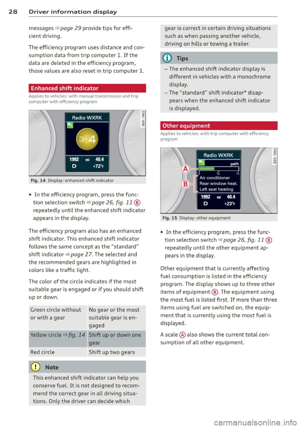
" In the efficiency program, press the func
tion selection switch¢
page 26, fig. 11@
repeatedly until the other equipment ap
pea rs in the display.
Other equ ipment that is currently affecting
fuel consumpt ion is listed in the eff iciency
program. The disp lay shows up to three other
items of equipment @. T he equipment using
the most fuel is listed first. If more than three
items using fuel are switched on, the equip
ment that is currently using the most fuel is
displayed.
A scale @also shows the current tota l con
sumption of all other equipment.
Page 32 of 302
30 Driver information display
Resetting the service interval display
Your authorized Audi dealer will reset the cor
responding service schedule after performing
the appropriate service on yo ur vehicle . Yo u
also have the possibility to reset the oil
change schedule after having performed an
oil change according to Audi specifications.
Select
I CAR I function button > Service interval
display > Reset oil change interval
or ICARI
function button> Car systems* control but
ton
> Servicing & checks > Reset oil change
interval.
(D Note
If you disconnect the battery terminals, no
calculations can be made for the serv ice
interval display during this time and no
service rem inder wi ll appear. Remember
that observing the proper service intervals
is vitally important to extend ing the life of
your vehicle, particu larly the eng ine, and
maintaining its value. Even if the mileage
driven is low, the maximum period of one
yea r from one service to the next must not
be exceeded .
@ Tips
-Do not reset the display between oil
changes, otherwise the display will be in
correct.
- The information in the Service Reminder
r ema ins stored even when the vehicle
battery is disconnected.
On-Board Diagnostic
system (OBD)
Malfunction Indicator Lamp (MIL)
The Malfunction Indicator Lamp (MIL) (4 i n
the instrument cluster is part of the On-Board
Diagnostic (OBD II) system.
The warning/indicator light illuminates when
the ignition is switched on and goes out after
the engine starts and the idle has stabilized .
This indicates that the MIL is working proper
ly.
If the light does not go out after the engine
is started, or illuminates while you are driv
ing, a malfunction may exist in the eng ine sys
tem . If the light illuminates, the catalytic con
verter could be damaged .
Continue driving
with reduced power (avoid
ing sustained high speeds and/or rapid accel
erations) and have the cond ition corrected.
Contact your authorized Audi dealer.
If the light illuminates, the electronic speed
limiter may also be malfunct ioning. For more
information
c:> page 31 , Electronic speed
limiter.
An improperly closed fuel filler cap may also
cause the
MIL light to illuminate
c:>page 217.
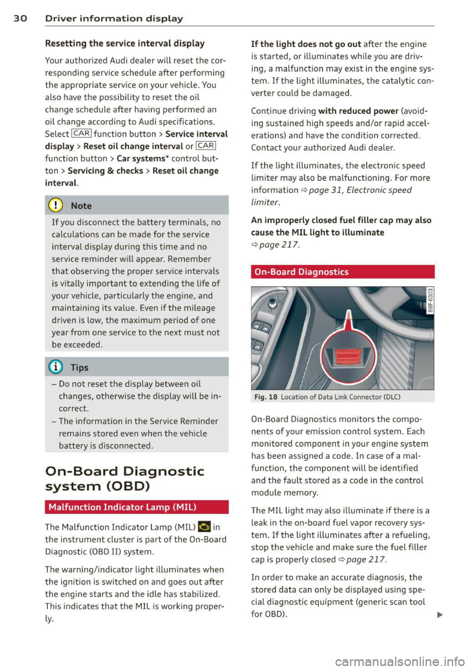
On-Board Diagnostics
Fig. 18 Locat io n of Data Link Con nector (D LC)
On-Board Diagnostics monitors the compo
nents of your emission control system . Each
monitored component in your engine system
has been assigned a code. In case of a mal
function, the component will be identified
and the fault stored as a code in the control
module memory.
The MIL light may also illuminate if there is a leak in the on-board fuel vapor recovery sys
tem. If the light illuminates after a refueling,
stop the vehicle and make sure the fuel filler
cap is properly closed
c:> page 217.
In order to make an accurate diagnosis, the
stored data can on ly be displayed using spe
c ial diagnostic equipment (generic scan tool
furOBD) .
~
Page 90 of 302
88 On the road
vehicle speed exceeds the set speed by about
3 mph (3 km/h). At the same time, a warning
symbol appears in the d isp lay . The symbol's
appeara nce m ight be d ifferent in some mod
els.
The speed warning system has one or two*
warn ing thresholds that f unct ion independ
ently of each other and that have somewhat
d ifferent purposes:
Speed warn ing 1
You can use speed warning 1 to set the maxi
m um speed w hile you are driv ing. T his setting
will remain in effect until you turn
off the igni
tion, assuming that you have not changed or
reset the setting.
The . (USA models)/ . (Canada models)
speed warning symbol in the warning 1 dis
p lay appears whe n you exceed the maximum
speed. It goes out when the speed fa lls below
the stored max imum speed .
The speed warning symbo l w ill also go out if
the speed
exceeds the stored max imum speed
by more than about 25 mph (40 km/h) for at
least 10 seconds. The stored maximum speed
is deleted .
Sett ing speed warning 1
c::> page 88.
Speed warning 2*
Sto ring warning 2 is recommended if you al
ways
want to be reminded of a certain speed,
for example when yo u are traveling in a coun
try that has a general maximum speed limit,
or if you do not want to exceed a specified
speed for winter tires.
The . (USA mode ls)/ . (Canada mode ls)
speed warning 2 symbo l appears in the dis
play when you exceed the stored speed lim it.
Unlike warning 1, it will not go out until the
vehicle speed drops below the stored speed
lim it.
Sett ing speed warning 2
c::> page 88.
(D Tips
Even tho ugh your vehicle is equipped with
a speed warning system, you should st ill watch the speedome
ter to ma ke s ure you
are not dr iving faster than the speed limit .
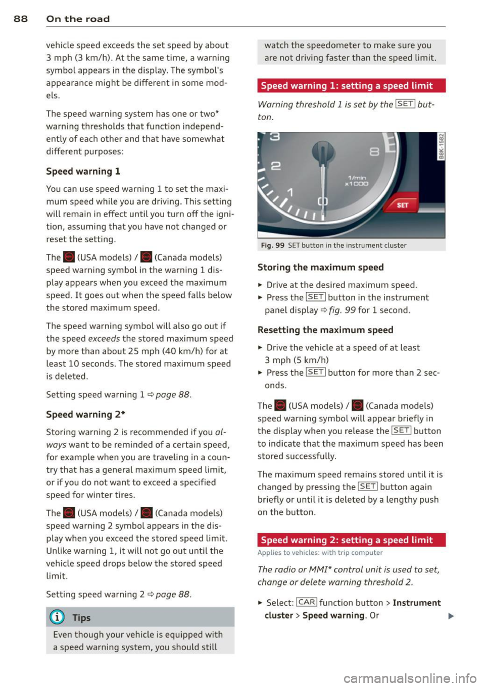
Speed warning 1: setting a speed limit
Warning threshold 1 is set by the ISETI but
ton.
F ig . 99 SET bu tton in the instr ume nt cluste r
Storing the max imum speed
.. Drive at the desired maximum speed .
.,. Press t he
ISE TI button in the instrument
panel disp lay
c::> fig . 99 for 1 second .
Resetting the maximum speed
.. Drive the vehicle at a speed of at least
3 mph (5 km/h)
.. Press the
ISET I button for more than 2 sec-
onds.
T he . (USA mode ls)/ . (Canada mode ls)
speed warning symbo l w ill appear briefly in
the display when you release the
I SE TI button
to indicate that the maximum speed has been
stored successfully.
The maximum speed remains stored until it is changed by pressing the
I SET ! button again
briefly or until it is deleted by a lengthy push
on the button.
Speed warning 2: setting a speed limit
App lies to vehicles: wi th trip co mp uter
The radio or MMI* control unit is used to set,
change or delete warning threshold 2.
.. Select: !CAR ! function b utton > In st rument
cluster > Speed warning .
Or