jack AUDI A4 2021 Owner´s Manual
[x] Cancel search | Manufacturer: AUDI, Model Year: 2021, Model line: A4, Model: AUDI A4 2021Pages: 304, PDF Size: 107.89 MB
Page 71 of 304
8W1012721BC
Sitting correctly and safely
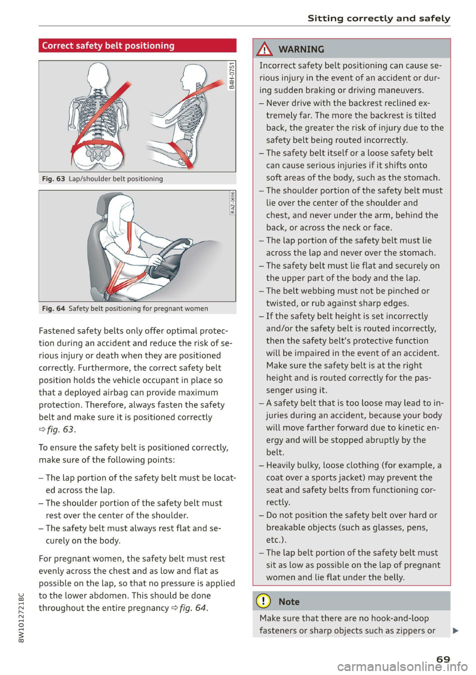
Correct safety belt positioning
B4H-0751
RAZ-0696
Fastened safety belts only offer optimal protec-
tion during an accident and reduce the risk of se-
rious injury or death when they are positioned
correctly. Furthermore, the correct safety belt
position holds the vehicle occupant in place so
that a deployed airbag can provide maximum
protection. Therefore, always fasten the safety
belt and make sure it is positioned correctly
> fig. 63.
To ensure the safety belt is positioned correctly,
make sure of the following points:
— The lap portion of the safety belt must be locat-
ed across the lap.
—The shoulder portion of the safety belt must
rest over the center of the shoulder.
— The safety belt must always rest flat and se-
curely on the body.
For pregnant women, the safety belt must rest
evenly across the chest and as low and flat as
possible on the lap, so that no pressure is applied
to the lower abdomen. This should be done
throughout the entire pregnancy > fig. 64.
ZA\ WARNING
Incorrect safety belt positioning can cause se-
rious injury in the event of an accident or dur-
ing sudden braking or driving maneuvers.
— Never drive with the backrest reclined ex-
tremely far. The more the backrest is tilted
back, the greater the risk of injury due to the
safety belt being routed incorrectly.
— The safety belt itself or a loose safety belt
can cause serious injuries if it shifts onto
soft areas of the body, such as the stomach.
— The shoulder portion of the safety belt must
lie over the center of the shoulder and
chest, and never under the arm, behind the
back, or across the neck or face.
— The lap portion of the safety belt must lie
across the lap and never over the stomach.
—The safety belt must lie flat and securely on
the upper part of the body and the lap.
— The belt webbing must not be pinched or
twisted, or rub against sharp edges.
— If the safety belt height is set incorrectly
and/or the safety belt is routed incorrectly,
then the safety belt's protective function
will be impaired in the event of an accident.
Make sure the safety belt is at the right
height and is routed correctly for the pas-
senger using it.
— A safety belt that is too loose may lead to in-
juries during an accident, because your body
will move farther forward due to kinetic en-
ergy and will be stopped abruptly by the
belt.
— Heavily bulky, loose clothing (for example, a
coat over a sports jacket) may prevent the
seat and safety belts from functioning cor-
rectly.
— Do not position the safety belt over hard or
breakable objects (such as glasses, pens,
etc.).
—The lap belt portion of the safety belt must
sit as low as possible on the lap of pregnant
women and lie flat under the belly.
@) Note
Make sure that there are no hook-and-loop
fasteners or sharp objects such as zippers or
69
>
Page 161 of 304
8W1012721BC
Parking and maneuvering
The driver must decide if the parking space
displayed is suitable for the vehicle.
— Certain conditions near the parking space
may cause the parking process to fail, such
as if the parking space is near trees or posts,
or if the ground is covered, for example,
with gravel, snow, or ice.
@) Tips
— Ifyou did not drive past a suitable parking
space too quickly, the parking space search
can also be activated afterward by pressing
Pe.
— The Electronic Stabilization Control (ESC)
must not be switched off during the parking
process. If the ESC intervenes, the parking
process
will be canceled.
— You can also drive into a perpendicular park-
ing space yourself and then activate the sys-
tem. If this is the case, the front of the vehi-
cle should already be in the space @)
=> page 157, fig. 131 so that the sensors
can measure the space.
— The system is not available when certain as-
sist systems are switched on.
— If there are suitable parking spaces on both
sides of the street, for example on a one-
way street, you can change the side where
the system is searching for parking spaces
by activating the turn signal for the other
side or by pressing on that side in the center
display.
— The park systems do not provide support for
assisted parking on tight curves.
Park assist
ere eure)
Applies to: vehicles with park assist
The park assist helps you when parking and exit-
ing parking spaces after the parking space
search. The park assist takes over the steering of
the vehicle while the driver accelerates, brakes,
and monitors the vehicle's surroundings. Park as-
sist can be interrupted at any time.
ZA\ WARNING
— Observe the safety precautions and note the
limits of the assist systems, sensors, and
cameras > page 117.
— The driver is always responsible when enter-
ing or exiting a parking space and during
similar maneuvers.
— Do not use this function if the vehicle cannot
move freely, for example when on a vehicle
jack.
— Sensors and cameras have spots in which
the surrounding area cannot be detected.
Objects, animals, and people may only be
detected with limitations may not be detect-
ed at all. Always monitor the traffic and the
vehicle's surroundings directly and do not
become distracted.
@) Note
— Do not use the park assist systems when
transporting cargo that extends out of the
vehicle, when snow chains are mounted, or
when the parking space is on a hill or in-
cline.
— Park assist guides the vehicle either away
from curbs or onto them if other vehicles
are parked on the curb. Make sure that your
vehicle's tires and rims are not damaged.
Resume control of the vehicle in time or
stop the parking process if needed to pre-
vent damage.
G) Tips
Follow the legal regulations in the country
where you are located when using Park assist.
Parking with the park assists
Applies to: vehicles with park assist
Requirement: a suitable parking space must be
found and selected > page 157. The vehicle must
initially be stationary.
In the center display, arrows and symbols on the
vehicle roof 2) > page 158, fig. 133 indicate
what action is needed, such as applying the
159
>
Page 263 of 304

8W1012721BC
Emergency assistance
Emergency assistance
General information
> Park the vehicle as far as possible from moving
traffic in the event of a breakdown. In the event
of a flat tire, park the vehicle ona level surface.
If you are ona steep hill, be especially careful.
> Set the parking brake.
> Switch the emergency flashers on.
> Have the passengers exit the vehicle. They
should move to a safe place, for example be-
hind a guard rail.
Z\ WARNING
Follow the steps given above. This is for your
protection and the for the safety of others on
the road.
Equipment
Vehicle tool kit, tire mobility kit, and
vehicle jack
Applies to: vehicles with the vehicle tool kit, tire mobility kit,
and vehicle jack
Fig. 169 Luggage compartment: cargo floor cover
The vehicle tool kit, vehicle jack, tire mobility kit
and compressor are stored in the luggage com-
partment under the cargo floor cover.
> Applies to: sedan: To open the front compart-
ment, lift the cargo floor cover by the strap (@).
> Applies to: allroad: To open the front compart-
ment, pull the cargo floor cover by the plastic
handle @) slightly toward the rear. Lift the car-
go floor cover over the front compartment.
> To open the rear compartment, lift the cargo
floor cover by the plastic handle @).
> Applies to: sedan: Engage the plastic handle @)
in the luggage compartment seal.
> To remove the cargo floor cover completely,
pull it toward the rear at the plastic handle @).
> Applies to: vehicles with spare tire: Turn the
handle counter-clockwise and remove the spare
tire.
> Applies to: sedan: Unhook the cargo floor cover
again
before closing the luggage compartment
lid.
Depending on vehicle equipment, the vehicle tool
kit, tire mobility kit, and compressor may be lo-
cated under another cover that is secured with a
handwheel.
Applies to: vehicles with vehicle jack in the stor-
age bag: The bag with the vehicle jack is secured
to the tie-downs in the luggage compartment
and must be secured to the tie-downs again after
using it.
ZX WARNING
Applies to: vehicles with vehicle jack in the storage bag
A vehicle jack that is unsecured, incorrectly se-
cured, or not secured in the luggage compart-
ment may slide out of place when braking,
turning,
or in an accident, which increases the
risk of injuries to vehicle passengers. To re-
duce the risk of an accident, never transport
the vehicle jack without securing it.
G) Tips
—Insome vehicles, the rear compartment
may not open.
— The vehicle jack in your vehicle is mainte-
nance-free.
Tire mobility kit
Applies to: vehicles with tire mobility kit
> Read and follow the important safety precau-
tions > page 261.
> Set the parking brake.
> Select the “P” position.
> Check if a repair with the tire mobility kit is pos-
sible > page 262.
261
Page 266 of 304
Emergency assistance
> Set the parking brake.
> Select the “P” position.
>» When towing a trailer: disconnect the trailer
from your vehicle.
> Lay out the vehicle tool kit > page 261 and the
spare tire > page 266.
>» Switch the ignition off.
> Turn the wheel bolt approximately one turn to
the left. To achieve the required torque, hold
the end of the wheel wrench*. If the wheel bolt
will not loosen, press carefully on the wheel
wrench* with your foot. Hold onto the vehicle
securely while doing this and make sure your
footing is stable.
ZA\ WARNING
The vehicle must also be secured to prevent it
from rolling when using the vehicle jack*. Use
suitable objects to block the front and back of
the wheel that is diagonal from the wheel
with the flat tire.
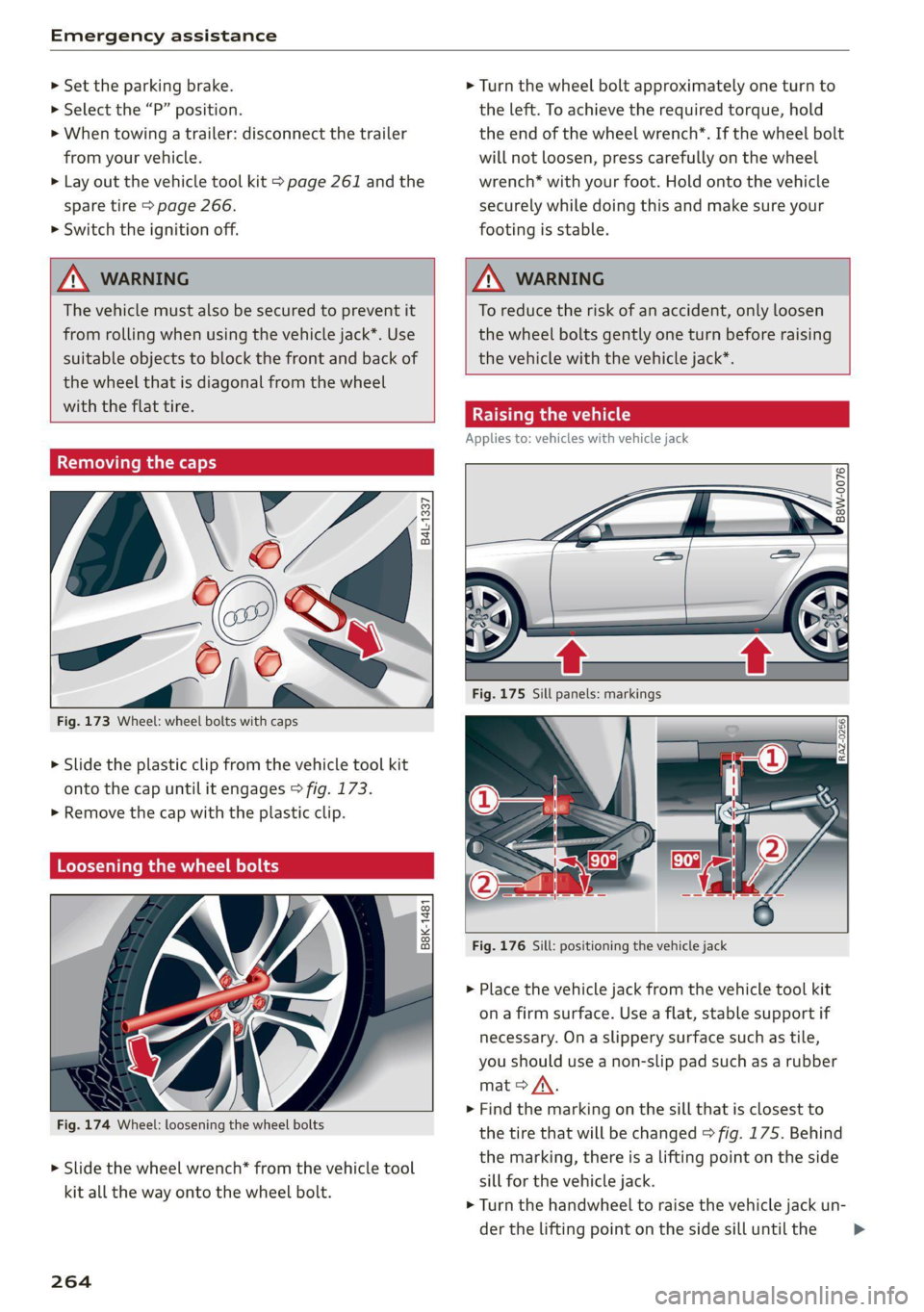
Removing the caps
@
=
(G)
me
as
Fig. 173 Wheel: wheel bolts with caps
?
> Slide the plastic clip from the vehicle tool kit
onto the cap until it engages > fig. 173.
> Remove the cap with the plastic clip.
Loosening the wheel bolts
©
i=
x © a
Fig. 174 Wheel: loosening the wheel bolts
> Slide the wheel wrench* from the vehicle tool
kit all the way onto the wheel bolt.
264
ZA WARNING
To reduce the risk of an accident, only loosen
the wheel bolts gently one turn before raising
the vehicle with the vehicle jack*.
Raising the vehicle
Applies to: vehicles with vehicle jack
© & Ss
g
= % oo
Fig. 176 Sill: positioning the vehicle jack
> Place the vehicle jack from the vehicle tool kit
ona firm surface. Use a flat, stable support if
necessary. Ona slippery surface such as tile,
you should use a non-slip pad such as a rubber
mat > A\.
> Find the marking on the sill that is closest to
the tire that will be changed > fig. 175. Behind
the marking, there is a lifting point on the side
sill for the vehicle jack.
> Turn the handwheel to raise the vehicle jack un-
der the lifting point on the side sill until the
Page 267 of 304
8W1012721BC
Emergency assistance
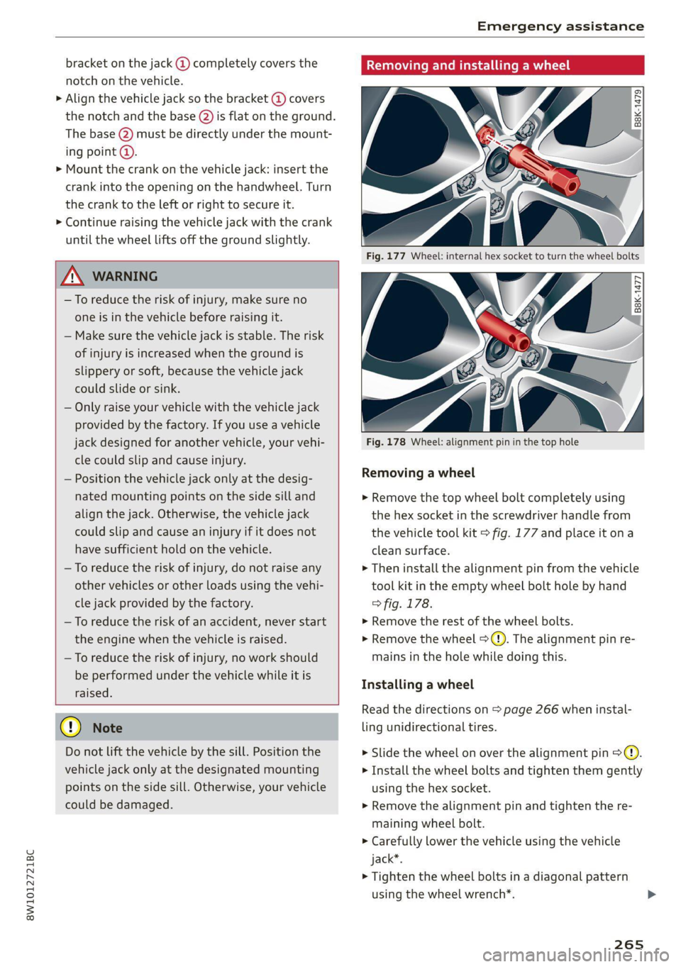
bracket on the jack @) completely covers the
notch on the vehicle.
> Align the vehicle jack so the bracket (@) covers
the notch and the base (2) is flat on the ground.
The base @) must be directly under the mount-
ing point @.
> Mount the crank on the vehicle jack: insert the
crank into the opening on the handwheel. Turn
the crank to the left or right to secure it.
> Continue raising the vehicle jack with the crank
until the wheel lifts off the ground slightly.
ZA WARNING
—To reduce the risk of injury, make sure no
one is in the vehicle before raising it.
— Make sure the vehicle jack is stable. The risk
of injury is increased when the ground is
slippery or soft, because the vehicle jack
could slide or sink.
— Only raise your vehicle with the vehicle jack
provided by the factory. If you use a vehicle
jack designed for another vehicle, your vehi-
cle could slip and cause injury.
— Position the vehicle jack only at the desig-
nated mounting points on the side sill and
align the jack. Otherwise, the vehicle jack
could slip and cause an injury if it does not
have sufficient hold on the vehicle.
—To reduce the risk of injury, do not raise any
other vehicles or other loads using the vehi-
cle jack provided by the factory.
— To reduce the risk of an accident, never start
the
engine when the vehicle is raised.
—To reduce the risk of injury, no work should
be performed under the vehicle while it is
raised.
() Note
Do not lift the vehicle by the sill. Position the
vehicle jack only at the designated mounting
points on the side sill. Otherwise, your vehicle
could be damaged.
Removing and installing a wheel
| B8K-1479
Fig. 178 Wheel: alignment pin in the top hole
Removing a wheel
> Remove the top wheel bolt completely using
the hex socket in the screwdriver handle from
the vehicle tool kit > fig. 177 and place it ona
clean surface.
> Then install the alignment pin from the vehicle
tool kit in the empty wheel bolt hole by hand
> fig. 178.
> Remove the rest of the wheel bolts.
>» Remove the wheel >(). The alignment pin re-
mains in the hole while doing this.
Installing a wheel
Read the directions on > page 266 when instal-
ling unidirectional tires.
> Slide the wheel on over the alignment pin >@.
> Install the wheel bolts and tighten them gently
using the hex socket.
> Remove the alignment pin and tighten the re-
maining wheel bolt.
> Carefully lower the vehicle using the vehicle
jack*.
> Tighten the wheel bolts in a diagonal pattern
using the wheel wrench*.
265
Page 295 of 304
8W1012721BC
HFP
refer to Hands Free Profile............. 162
High beams
High beam assistant.................4. 52
Highway lights ....... 0... cece eee eee ee ee 51
Hill descent assist..............02-000. 108
Hill descent control............0 eee eee 107
Hill hold assist... 0.0.2... ee ee eee eee 97
Home
refer to Home address...........-000% 187
Home address ....... 0.00.0. c eee eee ee 187
HomeLink
refer to Garage door opener............. 48
Home screen... ... 2. eee e eee eee eee eee 18
HOM... eee eee 6
Hotspot
refer to Wi-Fi...........0. 2.0 e eee eee 176
I
Idle
fefer to Gears ewes ¢ s ewes ce seen cs wees 8: 97
Ignition
Switching onvand Off". wes x y says « ¢ caver « 9 95
Imbalance (wheels) ............000000 0s 244
Immobilizer
refer to Electronic immobilizer........... 37
Indicatorlights » neow ¢ a wes ¢ ewer ws wares ao ee 7
INSpPectionintetWals ¢ ssw < gapen g x paves se ne 233
INStroMment ClUStErs = wasn s x wom » x eowe sy ew 12
Adjusting the layout................00. 13:
Cleaning........ 0... eee eee eee eee 258
ENGin@: code: « = sas ¢ seas ¢ eee ae Heese 215
Failures: «osc 2s mene oe pews se ee ¥ ee 12
On-board computer............00200 eee 16
Operating...............2.. 0.02.0 000 13
Service interval display................ 233
Software information................. 215
Switching tabs..................200005 13
Switching the view............ 00ers 13
Vehicle functions................00000- 16
Version information...............0-5 215
Instruments
Adjusting illumination.................. 55
Integrated Toll Module................. 125
Intelligent search
Navigation’: « s sxe 5 ¢ caw + + seein s o tees = 182
Interior lighting « . esccms ve ewe ve mes vw 54,55
Interior MONitOriNg’s + 2 wesw ce wows s ween a ae 36
Intermittent mode (windshield wipers) ..... 58
International’ travel... seessieivaseveuea Li?
Internet
veferto:connects =» ssw ss wees eo wes 2 oe 173
Internet radio
refer to Online radio.............. 197,198
iPhone
refer to Audi music interface........... 202
J
Jump starting......................00. 268
K
ROY". ccanees i a: sonra i ot samme +o anames o 9 ames @ 33,37
Convenience opening and closing......... 46
Key replacement.........c:eecceeeeees 37
Mechanical key...........0...000 02000 37
PANIC button ....... 2.20... 00 cece eee eee 38
Replacing the battery.................. 39
Unlocking and locking.............e eee 38
Vehicle code... 6.2.2... eee eee eee eee 37
Key user... 2... ee eee ee eee 31
RICK EOWING. « ccenerts «a: eames 0 a ayngen eo acne 9 me 99
L
Lane assist
refer to Audi active lane assist.......... 141
Lane departure warning
refer to Audi active lane assist.......... 141
Laptimer........... 0.000000. 0.0 2000. 124
Evaluating s « saws « & cae & & eee so ees os 125
StANEIINGsis 6 & conse w o owen 7 cummins & 7 aE & > 124
LATCH (securing child safety seats)......... 78
Leather care and cleaning............... 258
Legal information
License subscriptions................. 215
Software information................. 215
Software licenseSicx « s wews ss wee s genes 215
Version information...............000- 21S
License plate: brackets + scies 6 seen 3 6 ser 283
Lifting points (vehicle jack).............. 264
293
Page 301 of 304
8W1012721BC
Repaltiseti. «. ico + 0 mass ov caw ¥ viemees ae os 261
Service life... . ee eee eee eee 244
TIVE PreSStiriws s < sews s ¢ eege & e ees ¥ Bo 245
Tire pressure monitoring system.... 252, 253
Tire pressure table.................00. 247
Tire pressure (trailer mode)............ 115
Treadwear indicators... 0000s sonia a een 244
Unidirectional................... 237, 266
Uniform tire quality grading............ 251.
Tires and wheels
Glossary of tire and loading terminology .. 238
Tires and vehicle load limits............ 248
Toll Module
refer to Integrated Toll Module......... 125
ToolS. 1... eee eee eee 261
Top tether anchor (securing the child safety
S@at) 6. eee eee 80
Touch display
Adjusting the brightness................ 19
Operating « « ses 2 6 mes 2 o waws s wawe we ¥ vrs 17
TOWING: + « sams 2 & eee 2 & emis 2 o pewE 2 & Bee 269
TOWING OOD. seavers «x omens ¢ x ees Fo ER a 2 oe 271
Towing protection monitoring............. 36
TPMS
Tire pressure monitoring system........ 253
Traffic incidents
refer to Online traffic information....... 190
Traffic information « secsia 2 2 wioww s owen ws acre 191,
Online traffic information.............. 190
Tiraffic famiassist 5 novos» sorte wo exes « + swore 138
Traffic light information................ 123
Traffic sign recognition................. L21
Traffic SIGNS ie: = ¢ sews + y saws 3 e ewes § ea 124
Trailer towing sc < = eee ¢ » meen 2s eee 2 ees 115
Tongue weights . visws ss sensu < w came + « eesue 115
Trailer load... 2... eee eee eee eee 115
TURMHASSISE
yess « os suneoe « 0 eestor 0 staneas a exo 146
TUM SIQMAlS eriiios oe evaens wo cnavene +o vara + renin 52
U
Uniform tire quality grading............. 251
Unlocking and locking................--. 33
BYsFEMMGTECONECOL,. cece os viaceue wo aussene © vane 38
Using the lock cylinder................. 36
With Audi connect vehicle control........ 39
With the central locking switch.......... 35
With the convenience key............... 38
Update (software) ..............2--000. 213
USB
Adapter... 0.2... ce eee eee eee eee eee 165
USB charging port..............00000005 82
USB drive
Supported types/formats.............. 207
USB stick
refer to Audi music interface........... 202
Users
LOCAL USERS sisi so eaume 6 o even © & swans #8 sere 30
myAudi users... 2.22... eee eee eee 30
Using residual heat..............00. 0000 93
V
Waletiparking siciss < «cosas no nests x 6 oneness « a ai 48
Vanity Mitotic o 3 wis 6 wanen 0 + acme & 6 coven 57
Vehicle
Care/cleaning............ cece eee eee ee 255
Dimensions .............000-.00 ee eee 286
Identification data...............0 000s 286
OUP ORSCNVICE coctine x 2 mses oo onesie wo aetne «6 260
Raising... 6... eee eee eee eee 264
StartiniG ce: « + aces « = wens 5 2 eee & o eee eo 95
Unlocking and locking...............05. 38
Vehiclescaresisns oo sca ee acer oo owen +o ons 255
Vehicle control services.............00.. 175
Vehicletdata labe@leys : « sw 2 «ewe 2 eames 2 2 2 286
Vehicle identification number............ 286
Vehicle jack... 22... ee eee eee ee eee 261
LITLINIG POINES: « o cews ¢ « www oo ews eo eee 264
Vehicle keys: « « see ys sees 4s sews se ews 33; 37
Vehicle starting system................. 103
Vehicle tool kit...............0000000-. 261
Ventilation...................0.0000 08 90
VIEW button... 2.6... eee eee eee eee 13
WoiGemalss x sas os snasnne ow winnsne 6 avateae ow « 168
Voice recognition system ...........ee sees 26
External... 6.0.0... cece eee eee ee 27
Operating’: « « ase < paves & HR B= ERE a oe 26
Ww
Warning lights
refer to Indicator lights...............0.. 7
299