technical data AUDI A5 2008 8T / 1.G Owners Manual
[x] Cancel search | Manufacturer: AUDI, Model Year: 2008, Model line: A5, Model: AUDI A5 2008 8T / 1.GPages: 313, PDF Size: 12.13 MB
Page 5 of 313
Contents3
Controls
Safety
Driving tips
General maintenance
Self-help
Technical data Airbag system
. . . . . . . . . . . . . . . . .
Description of airbag system . . . .
Front airbags . . . . . . . . . . . . . . . . . .
Side airbags . . . . . . . . . . . . . . . . . . .
Head-protection airbags
(sideguard) . . . . . . . . . . . . . . . . . . . .
Deactivating the front passenger's
airbag via the key-operated switch
Child safety
. . . . . . . . . . . . . . . . . . . .
Points to remember if children are
travelling in the car . . . . . . . . . . . . .
Child safety seats . . . . . . . . . . . . . .
Fitting child safety seats . . . . . . . .
Driving tips
. . . . . . . . . . . . . . . .
Intelligent technology
. . . . . . . . . .
Electronic stabilisation program
(ESP) . . . . . . . . . . . . . . . . . . . . . . . . . .
Brakes . . . . . . . . . . . . . . . . . . . . . . . .
Power steering (servotronic) . . . . .
Four-wheel drive (quattro®) . . . . . .
Power management . . . . . . . . . . . .
Your vehicle and the
environment
. . . . . . . . . . . . . . . . . . .
Running in . . . . . . . . . . . . . . . . . . . .
Emission control systems . . . . . . .
Driving abroad . . . . . . . . . . . . . . . . .
How to improve economy and
minimise pollution . . . . . . . . . . . . .
Environmental compatibility . . . . .
Towing a trailer
. . . . . . . . . . . . . . . .
Driving the vehicle with a trailer or
caravan . . . . . . . . . . . . . . . . . . . . . . .
Removable towing bracket . . . . . .
General maintenance
. .
Care of vehicle and cleaning
. . .
General notes . . . . . . . . . . . . . . . . . .
Care of exterior . . . . . . . . . . . . . . . . .
Care of interior . . . . . . . . . . . . . . . . .
Fuel and filling the tank
. . . . . . . .
Petrol . . . . . . . . . . . . . . . . . . . . . . . . .
Diesel . . . . . . . . . . . . . . . . . . . . . . . . .
Filling the tank . . . . . . . . . . . . . . . . .
Checking and topping up fluidsBonnet . . . . . . . . . . . . . . . . . . . . . . . .
Engine compartment layout . . . . .
Engine oil . . . . . . . . . . . . . . . . . . . . . .
Cooling system . . . . . . . . . . . . . . . . .
Brake fluid . . . . . . . . . . . . . . . . . . . . .
Battery . . . . . . . . . . . . . . . . . . . . . . . .
Windscreen washer . . . . . . . . . . . . . Wheels and tyres
. . . . . . . . . . . . . . .
Wheels . . . . . . . . . . . . . . . . . . . . . . . .
Accessories and modifications
to the vehicle
. . . . . . . . . . . . . . . . . . .
Accessories and replacement
parts . . . . . . . . . . . . . . . . . . . . . . . . . .
Modifications . . . . . . . . . . . . . . . . . .
Radio transmitters and business
equipment . . . . . . . . . . . . . . . . . . . . .
Self-help
. . . . . . . . . . . . . . . . . . . . .
Self-help
. . . . . . . . . . . . . . . . . . . . . . . .
Warning triangle . . . . . . . . . . . . . . . .
First-aid kit . . . . . . . . . . . . . . . . . . . . .
Fire extinguisher . . . . . . . . . . . . . . . .
To o l s a n d T y r e M o b i l i t y S y s t e m . . .
Compact temporary spare wheel*
Tyre repairs . . . . . . . . . . . . . . . . . . . .
Changing a wheel . . . . . . . . . . . . . .
Jump-starting . . . . . . . . . . . . . . . . . .
Tow-starting and towing away . . .
Fuses and bulbs
. . . . . . . . . . . . . . . .
Fuses . . . . . . . . . . . . . . . . . . . . . . . . . .
Bulbs . . . . . . . . . . . . . . . . . . . . . . . . . .
Changing bulbs for headlights . . .
Changing bulb for turn signals . . .
Changing bulb for side lights . . . . .
Changing bulb for front fog lights
Changing bulbs for rear lights in
side panel . . . . . . . . . . . . . . . . . . . . . .
Changing bulbs in boot lid . . . . . . .
Number plate light . . . . . . . . . . . . . . 176
176
178
180
181
183
185
185
186
189
195
196
196
199
201
201
202
205
205
205
205
206
207208
208
211
219
220
220
220
223
227
227
227
228
230
230
232
233
235
238
239
242
243
243250
250
250
251
253
254
254
254
255
255
256
257
260
265
267
272
272
276
278
282
282
283
284
286
288
document_0900452a8179700c.book Seite 3 Donnerstag, 22. März 2007 10:19 10
Page 6 of 313
Contents 4Technical data
. . . . . . . . . . . .
General notes
. . . . . . . . . . . . . . . . . .
Explanation of technical data . . . .
Dimensions . . . . . . . . . . . . . . . . . . . .
Capacities . . . . . . . . . . . . . . . . . . . . .
Vehicle identification data . . . . . . .
Performance, weights and
dimensions
. . . . . . . . . . . . . . . . . . . . .
Petrol engines . . . . . . . . . . . . . . . . . .
Diesel engines . . . . . . . . . . . . . . . . . .
Index
. . . . . . . . . . . . . . . . . . . . . . . . .291
292
292
292
293
293
295
295
297
301
document_0900452a8179700c.book Seite 4 Donnerstag, 22. März 2007 10:19 10
Page 7 of 313
Notes on this Owner's Manual5
Controls
Safety
Driving tips
General maintenance
Self-help
Technical data
Notes on this Owner's ManualThis Owner's Manual contains important information, tips, sugges-
tions and warnings.
Please ensure that this Owner's Manual is always kept in the vehicle.
It should always be available to anyone else driving the vehicle, i.e.
anyone renting, borrowing or buying the vehicle from you.
This manual describes the equipment available for the vehicle at the
time of going to print. Some of the equipment described here will
not be available until a later date, or may only be available in certain
markets.
Some sections of this Owner's Manual do not apply to all vehicles.
If this is the case, a text at the start of the section indicates which
vehicles it applies to, e. g. “Applies to vehicles: with auxiliary
heater”. This optional equipment is also marked with an asterisk “*”.
Illustrations are intended as a general guide, and may vary from the
equipment fitted in your vehicle in some details.
At the beginning of this Owner's Manual, you will find a table of
contents showing all the items described in this manual in the order
in which they appear. An alphabetical index is included at the end
of the Owner's Manual.
All references to positions such as “left”, “right”, “front” or “rear”
are given as seen facing in the direction of travel.
* optional equipment
The section is continued on the following page.
Denotes the end of a section.
®Registered trademarks are marked ®. However, the absence of
this symbol does not constitute a waiver of the rights
concerning any proprietary name.
⇒ Refers to a “WARNING” within the same section. If the
WARNING symbol is followed by a page number the warning text
referred to is included in a different section.
WARNING
Texts with this symbol contain safety information. They warn you
of serious dangers, possibly involving accident or injury.
Caution
Texts with this symbol draw your attention to a possible risk of
damage to your vehicle.
For the sake of the environment
Texts with this symbol refer to points relevant to the protection of
the environment.
Note
Texts with this symbol contain additional information of a more
general nature.
document_0900452a8179700c.book Seite 5 Donnerstag, 22. März 2007 10:19 10
Page 11 of 313
Controls and displays9
Controls
Safety
Driving tips
General maintenance
Self-help
Technical data
Controls and displaysOverview
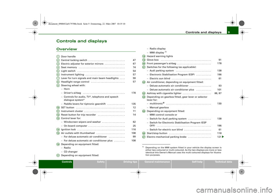
Door handle
Central locking switch . . . . . . . . . . . . . . . . . . . . . . . . . . .
Electric adjuster for exterior mirrors . . . . . . . . . . . . . . .
Seat memory . . . . . . . . . . . . . . . . . . . . . . . . . . . . . . . . . .
Light switch . . . . . . . . . . . . . . . . . . . . . . . . . . . . . . . . . . .
Instrument lighting . . . . . . . . . . . . . . . . . . . . . . . . . . . . .
Lever for turn signals and main beam headlights . . . .
Headlight range control . . . . . . . . . . . . . . . . . . . . . . . . .
Steering wheel with:
−Horn
−Driver's airbag . . . . . . . . . . . . . . . . . . . . . . . . . . . . . . .
−Controls for audio, TV*, telephone and speech
dialogue system*
−Paddle levers for tiptronic gearshift . . . . . . . . . . . . .
SET button . . . . . . . . . . . . . . . . . . . . . . . . . . . . . . . . . . . .
Instrument cluster . . . . . . . . . . . . . . . . . . . . . . . . . . . . . .
Reset button for trip recorder . . . . . . . . . . . . . . . . . . . .
Control lever for:
−Windscreen wipers and washer . . . . . . . . . . . . . . . . .
−On-board computer . . . . . . . . . . . . . . . . . . . . . . . . . . .
Ignition lock . . . . . . . . . . . . . . . . . . . . . . . . . . . . . . . . . . .
Air outlets with thumbwheel . . . . . . . . . . . . . . . . . . . . .
−For deluxe automatic air conditioner . . . . . . . . . . . .
−For deluxe automatic air conditioner plus . . . . . . . .
Depending on equipment fitted:
−Radio
−CD changer
Depending on equipment fitted:−Radio display
−MMI display
1)
Hazard warning lights
Glove box . . . . . . . . . . . . . . . . . . . . . . . . . . . . . . . . . . . . .
Front passenger's airbag . . . . . . . . . . . . . . . . . . . . . . . . .
Switches for the following (as applicable):
−Audi parking system . . . . . . . . . . . . . . . . . . . . . . . . . .
−Electronic Stabilisation Program (ESP) . . . . . . . . . . .
−Electric sun blind . . . . . . . . . . . . . . . . . . . . . . . . . . . . .
Air conditioner, depending on equipment fitted:
−Deluxe automatic air conditioner . . . . . . . . . . . . . . . .
−Deluxe automatic air conditioner plus . . . . . . . . . . .
Ashtray with cigarette lighter . . . . . . . . . . . . . . . . . . . . .
Depending on gearbox fitted, gear lever or selector
lever for:
−multitronic
® . . . . . . . . . . . . . . . . . . . . . . . . . . . . . . . . .
−Manual gearbox
Depending on equipment fitted:
−MMI control console or
−Switch for Audi parking system . . . . . . . . . . . . . . . . .
−Switch for Electronic Stabilisation Program (ESP
OFF) . . . . . . . . . . . . . . . . . . . . . . . . . . . . . . . . . . . . . . . .
−Switch for electric sun blind . . . . . . . . . . . . . . . . . . . .
Start/stop button . . . . . . . . . . . . . . . . . . . . . . . . . . . . . . .
Electro-mechanical parking brake . . . . . . . . . . . . . . . . .
A1A2
47
A3
67
A4
74
A5
54
A6
57
A7
59
A8
57
A9
178
135
A10
12
A11
11
A12
14
A13
62
25
A14
116
A15
108
99
108
A16A17
1)Depending on the MMI system fitted in your vehicle the display screen is
either two-coloured or multi-coloured. As the two displays are more or less
identical this Owner's Manual uses the multi-coloured displays for illustra-
tion purposes.A18A19
91
A20
178
A21
138
196
61
A22
93
101
A23
86, 87
A24
130
A25
138
196
61
A26
118
A27
121
document_0900452a8179700c.book Seite 9 Donnerstag, 22. März 2007 10:19 10
Page 13 of 313
Instruments and warning/indicator lamps11
Controls
Safety
Driving tips
General maintenance
Self-help
Technical data
Instruments and warning/indicator lampsInstrumentsInstrument cluster overview
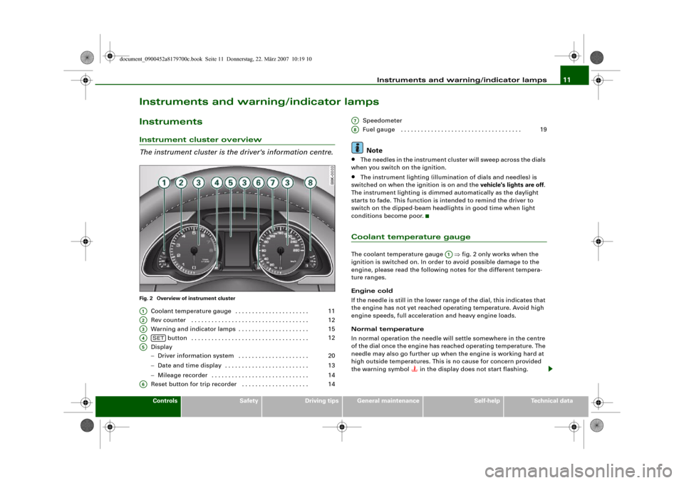
The instrument cluster is the driver's information centre.Fig. 2 Overview of instrument cluster
Coolant temperature gauge . . . . . . . . . . . . . . . . . . . . . .
Rev counter . . . . . . . . . . . . . . . . . . . . . . . . . . . . . . . . . . .
Warning and indicator lamps . . . . . . . . . . . . . . . . . . . . .
button . . . . . . . . . . . . . . . . . . . . . . . . . . . . . . . . . . .
Display
−Driver information system . . . . . . . . . . . . . . . . . . . . .
−Date and time display . . . . . . . . . . . . . . . . . . . . . . . . .
−Mileage recorder . . . . . . . . . . . . . . . . . . . . . . . . . . . . .
Reset button for trip recorder . . . . . . . . . . . . . . . . . . . . Speedometer
Fuel gauge . . . . . . . . . . . . . . . . . . . . . . . . . . . . . . . . . . . .
Note
•
The needles in the instrument cluster will sweep across the dials
when you switch on the ignition.
•
The instrument lighting (illumination of dials and needles) is
switched on when the ignition is on and the vehicle's lights are off.
The instrument lighting is dimmed automatically as the daylight
starts to fade. This function is intended to remind the driver to
switch on the dipped-beam headlights in good time when light
conditions become poor.
Coolant temperature gaugeThe coolant temperature gauge ⇒fig. 2 only works when the
ignition is switched on. In order to avoid possible damage to the
engine, please read the following notes for the different tempera-
ture ranges.
Engine cold
If the needle is still in the lower range of the dial, this indicates that
the engine has not yet reached operating temperature. Avoid high
engine speeds, full acceleration and heavy engine loads.
Normal temperature
In normal operation the needle will settle somewhere in the centre
of the dial once the engine has reached operating temperature. The
needle may also go further up when the engine is working hard at
high outside temperatures. This is no cause for concern provided
the warning symbol
in the display does not start flashing.
A1
11
A2
12
A3
15
A4
SET
12
A5
20
13
14
A6
14
A7A8
19
A1
document_0900452a8179700c.book Seite 11 Donnerstag, 22. März 2007 10:19 10
Page 15 of 313
Instruments and warning/indicator lamps13
Controls
Safety
Driving tips
General maintenance
Self-help
Technical data The button has the following functions:
Activating clock, date, temperature and mileage
recorder displays
The display will appear for about 30 seconds if you press the
button ⇒page 12, fig. 3 when the ignition is switched off.
Starting check procedure (auto-check control)
The auto-check control checks important components and vehicle
systems. These background checks are run constantly, as long as
the ignition is switched on ⇒page 29.
You can start the “check procedure” manually by pressing the
button with the ignition switched on. This function check can be
started at road speeds up to 5 km/h.
Calling up driver messages again
A red or yellow symbol appearing in the instrument cluster display
is normally accompanied by a corresponding message. The
message will disappear from the display after about 5 seconds. If
required, you can call up the message again by briefly pressing the
button.
Setting speed warning
You can press the button briefly to set speed limit warning 1
while the vehicle is moving ⇒page 28. If you press and hold the
button, this will cancel the speed warning.
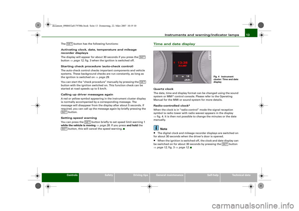
Time and date displayQuart z clock
The date, time and display format can be changed using the sound
system or MMI* control console. Please refer to the Operating
Manual for the MMI or sound system for more details.
Radio-controlled clock*
When the clock is in “radio-control” mode the signal reception
symbol (a radio tower with radio waves) appears in the display
⇒fig. 4. It is then not possible to change the minutes or the date
manually.
Note
•
The digital clock and mileage recorder displays are switched on
for about 30 seconds when the driver's door is opened.
•
When the ignition is switched off, the clock and date display can
be switched on for about 30 seconds by pressing the button
⇒page 12, fig. 3 ⇒page 12.
SET
SETSET
SET
SET
SET
Fig. 4 Instrument
cluster: Time and date
display
SET
document_0900452a8179700c.book Seite 13 Donnerstag, 22. März 2007 10:19 10
Page 17 of 313
Instruments and warning/indicator lamps15
Controls
Safety
Driving tips
General maintenance
Self-help
Technical data
Warning and indicator lampsOverview
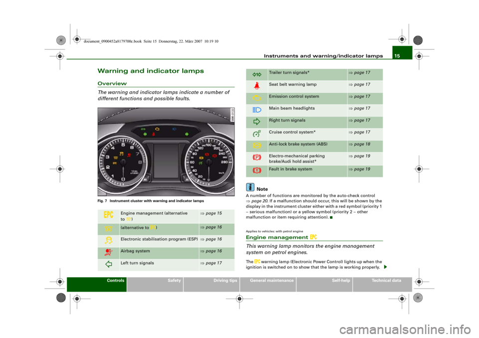
The warning and indicator lamps indicate a number of
different functions and possible faults.Fig. 7 Instrument cluster with warning and indicator lamps
Note
A number of functions are monitored by the auto-check control
⇒page 20. If a malfunction should occur, this will be shown by the
display in the instrument cluster either with a red symbol (priority 1
– serious malfunction) or a yellow symbol (priority 2 – other
malfunction or item requiring attention).Applies to vehicles: with petrol engineEngine management
This warning lamp monitors the engine management
system on petrol engines.The
warning lamp (Electronic Power Control) lights up when the
ignition is switched on to show that the lamp is working properly.
Engine management (alternative
to)
⇒page 15
(alternative to
)
⇒page 16
Electronic stabilisation program (ESP)
⇒page 16
Airbag system
⇒page 16
Left turn signals
⇒page 17
Trailer turn signals*
⇒page 17
Seat belt warning lamp
⇒page 17
Emission control system
⇒page 17
Main beam headlights
⇒page 17
Right turn signals
⇒page 17
Cruise control system*
⇒page 17
Anti-lock brake system (ABS)
⇒page 18
Electro-mechanical parking
brake/Audi hold assist*
⇒page 19
Fault in brake system
⇒page 19
document_0900452a8179700c.book Seite 15 Donnerstag, 22. März 2007 10:19 10
Page 19 of 313
Instruments and warning/indicator lamps17
Controls
Safety
Driving tips
General maintenance
Self-help
Technical data
WARNING
If a malfunction should occur, have the system checked immedi-
ately by a qualified workshop. If this is neglected, there is a risk
that the airbag system and/or belt tensioners may not be acti-
vated in an accident.Turn signals
Depending on which turn signal is operated, either the left
or
right
indicator lamp flashes. Both indicator lamps will flash when
the hazard warning lights are switched on.
If one turn signal should fail, the indicator lamp will start flashing
twice as fast.
This does not apply when towing a caravan or trailer. The indicator
lamp will stop flashing if one of the turn signals on the vehicle or the
caravan/trailer should fail. For further information on the turn
signals ⇒page 59.
Applies to vehicles: with towing bracketTrailer turn signals
The indicator lamp flashes when the turn signals are
operated while towing a caravan or trailer.The indicator lamp
flashes when the turn signals are operated,
provided a caravan or trailer is correctly attached and connected to
the vehicle.
The indicator lamp will not flash if one of the turn signals on the
trailer fails.
Seat belt warning lamp
The warning lamp acts as a reminder to fasten the seat
belts.After switching on the ignition, the warning lamp
will remain lit
until the driver and front passenger (if applicable) have fastened
their seat belts. When the vehicle has gathered speed you will also
hear a warning chime.
For further information on the seat belts ⇒page 170.
Emission control system
If the warning lamp lights up continuously you should take your
vehicle to a qualified workshop as soon as possible in order to have
the fault rectified.
If the warning lamp flashes drive on at reduced speed and seek
professional help in order to avoid damage to the catalytic
converter.
For further information on the catalytic converter ⇒page 205.Main beam headlights
The indicator lamp
lights up when the main beams are on or
when the headlight flasher is operated.
For further information on the main beam headlights ⇒page 59.
Applies to vehicles: with cruise control systemCruise control
The indicator lamp
in the instrument cluster lights up when the
cruise control system is operating.
document_0900452a8179700c.book Seite 17 Donnerstag, 22. März 2007 10:19 10
Page 21 of 313
Instruments and warning/indicator lamps19
Controls
Safety
Driving tips
General maintenance
Self-help
Technical data
Electro-mechanical parking brake
This warning lamp monitors the electro-mechanical
parking brake.The warning lamp
lights up when the parking brake is applied
with the ignition on. After the ignition has been switched off the
lamp will stay on for about 30 seconds. The warning lamp will light
up for about 30 seconds if the parking brake is applied with the igni-
tion switched off.
The warning lamp should go out when the parking brake is released.
If the warning lamp flashes continuously after the parking brake has
been applied, the brake may not be strong enough to hold the
vehicle on a slope. This may be due to the brakes overheating.
Please note the following points:
•
If the gradient is too steep to park the vehicle safely, the display
will show the message Caution: Vehicle parked too steep.
•
In the event of a fault in the parking brake system the symbol
will also appear in the instrument cluster display together with the
message Parki ng b rake! You should have the fault corrected by a
qualified workshop without delay.
Brake system
The warning lamp flashes if the brake fluid level is too low
or if there is a fault in the ABS system or the parking
brake.If the warning lamp
flashes, there is a fault in the brake system.
The symbol
in the instrument cluster display will flash at the
same time. You can press the button to obtain a message
explaining the fault ⇒page 31.
If a failure should occur in the ABS, the ABS warning lamp
will
light up together with the brake warning lamp
⇒.
WARNING
•
Before opening the bonnet and checking the brake fluid level,
observe the warning information on ⇒page 231, “Working on
components in the engine compartment”.
•
If the brake warning lamp does not go out, or if it lights up
when driving, the brake fluid level in the reservoir is too low – this
may cause an increased accident risk. Stop the vehicle and do not
drive on. You should obtain professional assistance.
•
If the brake warning lamp lights up together with the ABS
warning lamp, this can mean that the control function of the ABS
is out of action. As a result the rear wheels can lock relatively
easily when braking. This could cause the tail of the vehicle to skid
sideways. Drive carefully to the nearest qualified workshop and
have the fault rectified.
Fuel gaugeThe gauge only works when the ignition is switched on.
When the needle reaches the reserve zone, the symbol
lights up
in the instrument cluster display ⇒page 36 together with the
message Please refuel. At this point there are still about 8 litres of
fuel left in the tank. This is your reminder to fill up soon.
The tank capacity of your vehicle is given in the Technical data
section ⇒page 293.
Caution
Never run the tank completely dry. If there is an irregular fuel supply,
misfiring can occur. This allows unburnt fuel to enter the exhaust
system, which could cause overheating and damage the catalytic
converter.
SET
document_0900452a8179700c.book Seite 19 Donnerstag, 22. März 2007 10:19 10
Page 23 of 313
Driver information system21
Controls
Safety
Driving tips
General maintenance
Self-help
Technical data
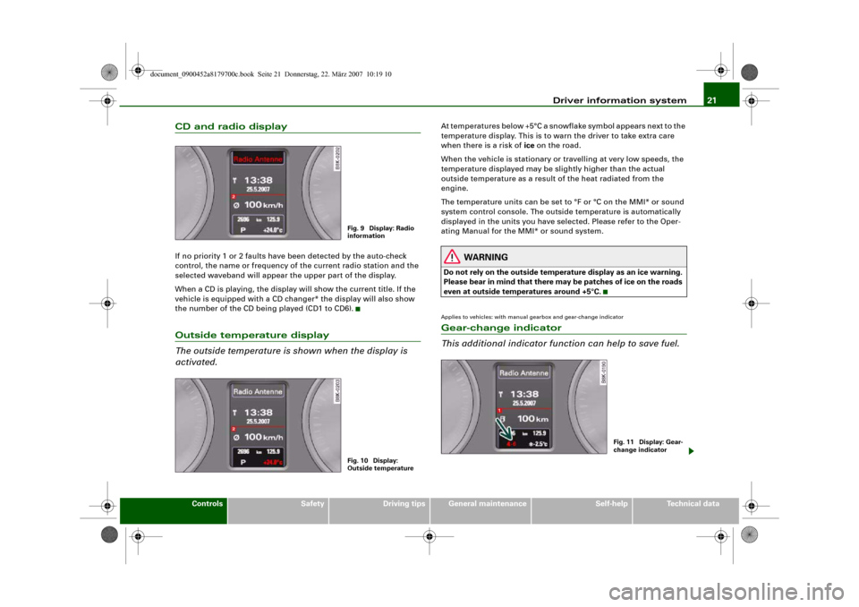
CD and radio displayIf no priority 1 or 2 faults have been detected by the auto-check
control, the name or frequency of the current radio station and the
selected waveband will appear the upper part of the display.
When a CD is playing, the display will show the current title. If the
vehicle is equipped with a CD changer* the display will also show
the number of the CD being played (CD1 to CD6).Outside temperature display
The outside temperature is shown when the display is
activated.
At temperatures below +5°C a snowflake symbol appears next to the
temperature display. This is to warn the driver to take extra care
when there is a risk of ice on the road.
When the vehicle is stationary or travelling at very low speeds, the
temperature displayed may be slightly higher than the actual
outside temperature as a result of the heat radiated from the
engine.
The temperature units can be set to °F or °C on the MMI* or sound
system control console. The outside temperature is automatically
displayed in the units you have selected. Please refer to the Oper-
ating Manual for the MMI* or sound system.
WARNING
Do not rely on the outside temperature display as an ice warning.
Please bear in mind that there may be patches of ice on the roads
even at outside temperatures around +5°C.Applies to vehicles: with manual gearbox and gear-change indicatorGear-change indicator
This additional indicator function can help to save fuel.
Fig. 9 Display: Radio
informationFig. 10 Display:
Outside temperature
Fig. 11 Display: Gear-
change indicator
document_0900452a8179700c.book Seite 21 Donnerstag, 22. März 2007 10:19 10