warning AUDI A5 COUPE 2010 Owners Manual
[x] Cancel search | Manufacturer: AUDI, Model Year: 2010, Model line: A5 COUPE, Model: AUDI A5 COUPE 2010Pages: 360, PDF Size: 84.39 MB
Page 318 of 360

lllffll.,___W_ h_ a _ t_d_ o_ l _d _o_ n_ o_ vv_ ? ______________________________________________ _
Fig. 244 Close-up:
proper positioning of
jack
The location of the jack point is indicated by an indentation
on the underside of the vehicle :::;,
page 315, fig. 243.
- Activate the
parking brake to prevent the vehicle from
rolling unintentionally.
Shift into
1st gear on vehicles with manual transmission
or move the selector lever to the
P position on vehicles
with automatic transmission*.
- Find the
lifting point in the sill that is closest to the faulty
wheel :::;,
page 315, fig. 243.
- Turn the handwheel on the
vehicle jack until the jaw
:::;, fig. 244 @ covers the
notch on the vehicle.
- Align the vehicle jack so the jaw @ covers the notch and
the base plate ® is flat on the floor. The base plate®
must be
vertical under the lifting point @.
Install the rod on the vehicle jack: Insert the rod into the
opening on the handwheel. Turn the rod left or right to
secure it.
- Continue raising the jack with the rod until the wheel lifts
off the ground slightly.
Only position the vehicle jack at the designated points~ page 315,
fig. 243. There is exactly one location for each wheel. Do not position
the jack in any other locations.
Soft ground under the jack can cause the vehicle to slip off the jack.
Always place the jack on firm ground. Use a flat, stable support if
necessary. Use a non -slip surface such as a rubber mat on a
slippery
surface
such as tile.
& WARNING
• You or your passengers could be injured while changing a
wheel if you do not follow these safety precautions:
-Positioning the jack under the vehicle at any other place than
those indicated above may damage the vehicle or may result in
personal injuries.
- A soft or unstable surface under the jack may cause the
vehicle to slip off the jack. Always provide a firm base for the
jack on the ground.
If necessary, use a sturdy board under the
jack.
- On hard, slippery surface (such as tiles) use a rubber mat or
similar to prevent the jack from slipping.
• To help prevent injury to yourself and your passengers:
- Do not raise the vehicle until you are sure the jack is securely
engaged.
- Passengers must not remain in the vehicle when it is jacked
up.
- Make sure that passengers wait
in a safe place away from
the vehicle and well away from the road and traffic.
- Make sure jack position is correct, adjust as necessary and
then continue to raise the jack. •
Page 320 of 360

-L___:W:..:..:. h.:.: a::.. t:...:: d:.:o:::....:. l..: d::. O ::::....: n:..:.:: O:..:W :.:..:. ? ____________________________________________ _
hub. Remove all dirt from these surfaces before remounting the
w he el.
• Do not use the he xagonal socket in the screwdriver hand le to
loo sen or tighten the wh eel bo lts.•
Tires with unidirectional tread design
T ir es with unid irecti onal trea d des ign m ust be moun ted
with th eir tread pattern poin ted in th e right dir ection .
Using a spare tire with a tread pattern intended for use
in a specific direction
When usi ng a s pa re t ire wi th a tre a d patte rn intended for use i n a
s p ecific direc tion, p lease note the following:
• Th e direc tio n of rot ati on is marke d by an
arrow on the side of the
tire .
• I f th e spare tir e has to be insta lled in th e incor rec t di recti on, use
the spare tire only temporar ily since the tir e will not be able to
ac hieve it s optimu m perf ormance cha rac te ris tic s wit h rega rd to
aqua plani ng, no ise and wea r.
• W e recom men d th at you pay pa rticu lar att ent ion to this f act
du ring wet weather and that you adjust your sp eed to match road
c o nditio ns.
• Replace the flat tire with a n ew on e and have i t installe d on your
v eh ic le as so on as possib le to re st ore th e handl ing a dvant ages of a
un idirectional tir e.•
Notes on wheel changing
P lease read the information=> page 299, "New tir es and r ep lacing
tir es a nd wh eels" if yo u are g oing t o use a spare t ire w hich is
differ ent from th e tires on your v ehicle.
A fter yo u change a ti re:
• Check the tire pressure on the spare immediately after installa
tion.
• Have the wheel bolt tightening torque checked with a torque
wrench as soon as possible by your authorized Audi dealer or a qualified workshop.
• With steel and alloy wheel rims , the wheel bolts are correctly
tightened at a torque of 90 ft lbs. 1120 Nm l.
• If you notice that the wheel bolts are corroded and difficult to
turn while changing a tire, they should be replaced before you check
the tightening torque .
• Replace the flat tire with a new one and have it installed on your
vehicle as soon as possible . Remount the wheel cover .
Until then , drive with extra care and at reduced speeds.
& WARNING
• If you are going to equip your vehicle with tires or rims which
differ from those which were factory installed , then be sure to read
the information
=> page 299 , "New tires and replacing tires and
wheels ".
• Always make sure the damaged wheel or even a flat tire and
the jack and tool kit are properly secured in the luggage compart ment and are not loose in the passenger compartment .
• In an accident or sudden maneuver they could fly forward,
injuring anyone in the vehicle .
• Always store damaged wheel , jack and tools securely in the
luggage compartment . Otherwise , in an accident or sudden
maneuver they could fly forward , causing injury to passengers in
the vehicle .
0 Note
Do not use commercia lly available tire sealants. Otherwise, the elec
tr ica l comp onents o f the tire pr essur e mon it o ring syste m * w ill n o .,
Page 322 of 360
lllffl!l.,___F_ u_ s_ e_s _ a_n _ d_ b_ u_lb _ s _______________________________________________ _
Fuses and bulbs
Fuses
Replacing a fuse
A problem in the electrical system may be caused by a
blown fuse.
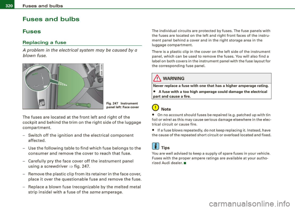
F ig . 247 Ins trume nt
pa nel l eft: Face c ov er
T he fuses are located at the front left and right of the
cockpit and behind the trim on the right side of the luggage
compartment .
- Switch off the ignitio n and the e lectr ica l component
affected.
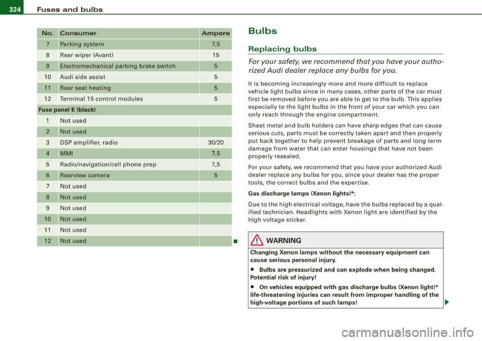
- Use t he fo llow ing tab le to find which f use belongs to the
consumer and remove the cover to reach that f use.
- Care fully pry t he face cover off the instrument pane l
using a screwdriver =:> fig. 247 .
Remove the plastic cl ip from its retainer in the face cover,
place it over the questionable fuse and remove the fuse.
Replace a blown fuse (recogn izable by the melted metal
strip inside) with a fuse of the
same amperage .
The individual circuits are protected by fuses. The fuse panels with
the fuses are located on the left and right front faces of the instru
ment pane l beh ind a cover and in the right storage area in the
luggage compartment.
There is a plastic clip in the cover on the lef t side of the instrument
panel, which can be used to remove the fuses. You w ill also find a
l abel on both covers in the ins trument panel with the fuse layout for
the corresponding fuse panel.
& WARNING
Nev er rep lace a fu se with one t hat h as a higher amper age r ating .
• A fuse with a too high amperage co uld damage the electric al
part and cau se a fir e.
0 Note
• On no account should fuses be repaired (e.g . patched up with tin
foil or wire) as this may cause serious damage elsewhere in the elec
trical circuit or cause fire .
• If a fuse blows repeated ly, do not keep replacing it . Instead, have
the cause of the repeated short circuit or overload located and fixed.
[ i ] Tip s
You are well advised to keep a supply of spare fuses in your vehic le.
Fuses wi th the proper ampere ratings are available at your autho
rized Audi dealer. •
Page 326 of 360
11111.___F_ u_ s _ e_s _ a_n _ d_ b_ u_lb _ s _______________________________________________ _
No. Consum er
7 Parking system
8 Rear wiper (Avant)
9 Electromechanical parking brake switch
10 Audi side assist
1 1 Rear seat heating
12 Terminal 15 control modu les
Fu se panel E (bla ck)
1 N ot used
2 Not used
3 DSP amp lifier, radio
4 MMI
5 Radio/navigation/cel l phone prep
6
Rearview camera
7 Not used
8 Not used
9 N ot used
10 Not us ed
1 1 Not used
12 Not used
Ampere
7,5
15 5
5
5
5
30/20
7,5
7,5
5
•
Bulbs
Replacing bulbs
For your s afety, we recommend th at you have your autho
ri zed Audi dealer replace any bulbs for you.
It is becoming increasingly more and more difficult to replace
vehic le light bulbs since in many cases, o ther parts of the car must
first be removed before you are able to get to the bu lb . This applies
especia lly to the light bu lbs in the front of your car which you can
only reach through the engine compartment .
Sheet metal and bulb holders can have sharp edges that can cause
serious cuts, parts must be correctly taken apart and then properly
put back together to help prevent breakage of parts and long term
damage from water that can enter housings that have not been
properly resealed.
Fo r your safety, we recommend that you have your authorized Audi
dea ler replace any bulbs for you, s ince your dealer has the proper
tools, the correct bulbs and the expertise.
Ga s di scharg e lamps (X enon ligh ts)*:
Due to the high electrical voltage, have the bulbs replaced by a qual
ified technician . Headlights with Xenon light are identified by the
high voltage sticker .
& WARNING
Changi ng Xeno n lamp s w ithout th e necess ary e quipm ent can
c a use se riou s pers on al injury .
• Bulb s are p ress urize d and can e xpl ode when being ch ange d.
Po tentia l ri sk of injury!
• On ve hic les equ ippe d with g as disc ha rg e bulb s (Xenon li ght )*
li fe -thre atening injuri es can re sult from impro per h andling of th e
hi gh-v olt age portion s of su ch lam ps! .,_
Page 327 of 360
Fuses and bulbs -
----------------
•
& WARNING (continu ed )
• Only your authorized Audi dealer or a qualified workshop
should change the bulbs in ga s discharge lamps. There are parts
with sharp edges on the openings and on the bu lb holders that
can cause seriou s cuts .
If you are uncertain about what to do ,
have the work performed by an authori zed Aud i dealer or other
qualified workshop. Serious personal injury may re sult from
improperly performed work .
[ i] Tips
• I f you sti ll prefer to replace the l ight bu lbs yourself, be aware that
t he engine compart ment is a ha zar do us area to w ork in =>
page 263,
"Engine compartment "=> & .
• I t is be st to as k yo ur aut ho rize d Audi d ealer wh enever you wa nt
to change a bulb .•
Do-it -yourself service
Page 328 of 360
lll'I.___E_ m_ e_r -=g :...e_ n _ c-=y _ s_ i_t _u _a _t_ i_o _n_ s _______________________________________________ _
Emergency situations
General
This chapter is intended for trained emergen cy crew s and working
personnel who have the necessary tools and equ ipment to perform
the se operations. •
Starting by pushing or towing
0 Note
Vehicles with an automatic tran smission cannot be started by
pushing or towing . •
Starting with jumper cables
If n ecess ary, the e ngin e c an b e starte d by conne ctin g it to
the ba ttery of anoth er vehicle .
If the engine shou ld fai l to start because of a discharged or weak
ba tte ry, the bat te ry can be connected t o the ba ttery of
another
vehic le, using a pair of jumper cables to start the engine.
Jumper cables
Use on/yjumper cables o f sufficient ly lar gecross section to carry the
s tarte r curre nt safe ly . Re fer to t he manu fac tur er's speci fica tions.
Use on ly jumper cables w ith
insulated terminal clamps w hich are
d istinct ly marked:
plus (+l cable in most cas es c olore d red
minus (-l cable in most cases co lored black .
& WARNING
Batteries contain electricity , acid , and gas . Any of these can cause
very serious or fatal injury. Follow the instructions below for safe
handling of your vehicle 's battery .
• Always shield your eyes and avoid leaning over the battery
whenever possible .
• A discharged battery can freeze at temperatures just below
32 °F (0 °C l. Before connecting a jumper cable , you must thaw the
frozen battery completely , otherwise it could explode.
• Do not allow battery a cid to contact eye s or skin . Flush any
contacted area with water immediately.
• Improper use of a booster battery to start a vehicle may cause
an explosion.
• Vehicle batteries generate e xplosive gases . Keep sparks, flame
and lighted cigarettes away from batteries.
• Do not try to jump start any vehicle with a low ac id level in the
battery.
• The voltage of the booster battery must also have a 12-Volt
rating . The capacity (Ahl of the booster battery should not be
lower than that of the discharged battery . Use of batteries of
different voltage or substantially different "Ah " rating may cause
an e xplosion and personal injury .
• Never charge a frozen battery. Gas trapped in the ice may cause
an explosion .
• Never charge or use a battery that has been frozen . The battery
case may have be weakened.
• Use of batteries of different voltage or substantially different
capacity (Ah ) rating may cause an explosion and injury . The
capacity (Ahl of the booster battery should not be lower than that
of the discharged battery . .,_
Page 329 of 360

________________________________________________ E_ m ___ e_r.::g ~e ___ n_c ~y:.- s;_ i_t _u :...:a:..:. t.:.: i...:o :...:n...:..:. s _ __,J_
& WARNING !continued)
• Before you check anything in the engine compartment, always
read and heed all WARNINGS~ page 263, "Engine compartment".
0 Note
• Applying a higher voltage booster battery will cause expensive
damage to sensitive electronic components, such as control units,
relays, radio, etc .
• There must be no electrical contact between the vehicles as
otherwise current could already start to flow as soon as the positive
(+) terminals are connected.
[ i) Tips
• The discharged battery must be properly connected to the
vehicle's electrical system. When jump starting or charging the
battery , never connect the negative ground cable to the battery
negative post because the battery manager system must be able to
detect the battery's state of charge. Always connect the negative
ground cable to the negative ground post of the battery manager
control unit .•
Use of jumper cables
Make sure to connect the jumper cable clamps in exactly
the order described below!
Fig. 251 Engine
compartment : Connec·
tors for jumper cables
and charger
Fig. 252 Jump starting
with the battery of
another vehicle: @
discharged vehicle
battery,
© booster
battery
The procedure described below for connecting jumper
cables is intended to provide a jump start for your vehicle.
Vehicle with discharged battery:
Turn off lights and accessories, move lever of automatic
transmission to
N (Neutral) or P (Park) and set parking
brake.
~
Vehicle care Do-it-yourself service irechnical data
Page 330 of 360

lllffl.___E_ m _ e _r-==g :...e_ n_ c...:y _ s_ i_t _u _a _t_ i_o _n_ s _______________________________________________ _
Conn ect POSITIVE
(+) to POSITIVE (+) (red )
- Remove the cover above the jump start connection.
- Open the red cover on the positive pole
~ page 327,
fig. 251.
1. Connect one end of the positive cable (red) on the
jump
start bolt~ page 327, fig. 252 G) (Bolts under red cover
= "positive") of the vehicle to be started @.
2. Connect the other end to the positive terminal @ of the
booster battery @.
Connect NEGATIVE (-) to NEGATIVE (-) (black)
3. Connect one end to the negat ive terminal 0 of the
booster battery ®·
4. Connect the other end of the negative cable (black) to the
jump start bolt@ (Bolts with hex head= "negative") of
the vehicle to be started @.
Starting the engine
- Start the engine of the vehicle with the booster battery.
Run the engine at a moderate speed.
- Start engine with discharged vehicle battery in the usual
manner.
- If the engine fails to start : do not keep the starter
cranking for longer than 10 seconds. Wait for about
30 seconds and then try again.
- With engine running, remove jumper cables from both
vehicles in the exact
reverse order .
- Close the red cover on the positive pole.
T he battery is vented to the outside to prevent gases from entering
th e vehicle interior. Make sure that the jumper clamps are well
connected with their
metal parts in full contact with the battery
terminals.
& WARNING
To avoid serious personal injury and damage to the vehicle , heed
all warnings and instructions of the jumper cable manufacturer.
If
in doubt, call for road service.
• Jumper cables must be long enough so that the vehicles do not
touch .
• When connecting jumper cables, make sure that they cannot
get caught in any moving parts in the engine compartment.
• Do not bend over the batteries -danger of chemical burns!
• The battery cell locking screws must be tightened securely.
• Before you check anything in the engine compartment , always
read and heed all WARNINGS ~ page 263, "Engine compartment".
0 Note
Improper hook-up of jumper cables can ruin the generator .
• Always connect POS ITIVE(+) to POS ITIVE(+), and NEGATIVE(-) to
NEGATIVE( -) ground post of the battery manager control unit .
• Check that all screw plugs on the battery cells are screwed in
firm ly. If not, tighten plugs prior to connecting clamp on negative
battery terminal.
• Please note that the procedure for connecting a jumper cable as
described above applies specifically to the case of your vehicle
being jump started . When you are giving a jump start to another
vehicle, do
not connect the negative(-) cable to the negative{-)
terminal on the discharged battery©~
page 327, fig. 252. Instead,
securely connect the negative(-) cable to either a solid metal
component that is firmly bolted to the engine block or to the engine ..
Page 331 of 360
________________________________________________ E_ m_ e_r ,,::g c..e_ n _ c..::y;._ s_ i_t _u _a_ t_ i_o _n_ s _ ___.ffllll
block itself. If the battery that is being charged does not vent to the
outside, escaping battery gas could ignite and explode! •
Emergency towing with commercial
tow truck
General hints
Your Audi requires special handling for towing.
The following information is to be used by commercial tow truck
operators who know how to operate their equipment safely.
• Never tow your Audi , towing will cause damage to the engine
and transmission.
• Never wrap the safety chains or winch cables around the brake
lines.
• To prevent unnecessary damage, your Audi must be transported
with a flat bed truck.
• To load the vehicle on to the flat bed, use the towing loop found
in the vehicle tools and attach to the front or rear anchorage
~ page 329 and ~ page 330.
& WARNING
A vehicle being towed is not safe for passengers. Never allow
anyone to ride in a vehicle being towed, for any reason. •
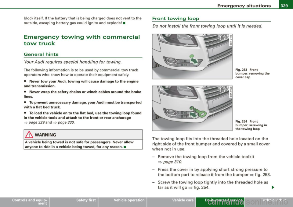
Front towing loop
Do not install the front towing loop until it is needed.
Fig. 253 Front
bumper: removing the
cover cap
Fig . 254 Front
bumper: screwing in
the towing loop
The towing loop fi ts into the thread ed hole located on the
r ight side of the front bumper and covered by a small cover
when not in use.
- Remove the towing loop from the vehicle toolkit
~ page 310.
- Press the cover in by applying short strong pressure to
the bottom part to release it from the bumper~ fig. 253.
- Screw t he towing loop tightly into the threaded hole as
far as it will go
~ fig. 254. ~
Vehicle care Do-it-yourself service irechnical data
Page 332 of 360
IIIII...__E_ m _ e _r.;:g '-e_ n_ c-=y _ s_ i_t _u _a _t_ i_o _n_ s _______________________________________________ _
When it is no longer needed, unscrew the towing loop and put it
back into the vehicle toolkit. Be sure to have the towing loop stored
in the vehicle at all times.
& WARNING
If the towing loop is not screwed in as far as it will go, the thread
can pull out when the vehicle is towed -potential risk of an
accident. •
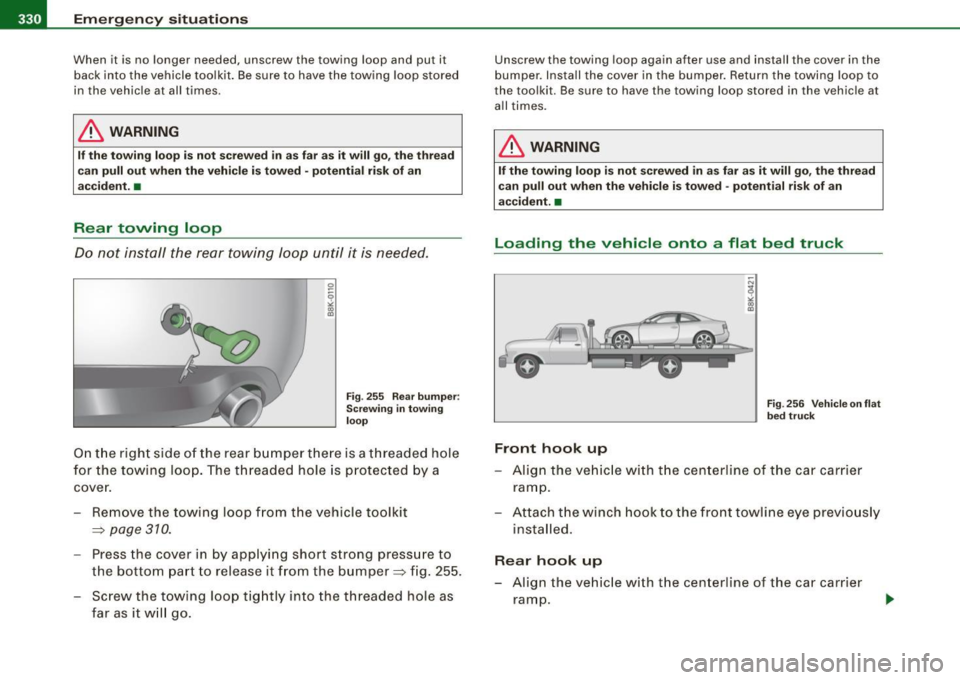
Rear towing loop
Do not install the rear towing loop until it is needed.
Fig. 255 Rear bumper :
Screwing in towing
loop
On the right side of the rear bumper there is a threaded hole
for the towing loop. The threaded hole is protected by a
cover.
- Remove the towing loop from the vehicle toolkit
=>
page 310.
- Press the cover in by applying short strong pressure to
the bottom part to release it from the bumper=> fig. 255.
Screw the towing loop tightly into the threaded hole as
far as it will go.
Unscrew the towing loop again after use and install the cover in the
bumper . Install the cover in the bumper. Return the towing loop to
the toolkit. Be sure to have the towing loop stored in the vehicle at
all times.
& WARNING
If the towing loop is not screwed in as far as it will go, the thread
can pull out when the vehicle is towed -potential risk of an
accident. •
Loading the vehicle onto a flat bed truck
Front hook up
Fig. 256 Vehicle on flat
bed truck
-Align the vehicle with the centerline of the car carrier
ramp.
- Attach the winch hook to the front towline eye previously
installed.
Rear hook up
- Align the vehicle with the centerline of the car carrier
ramp.