battery AUDI A5 COUPE 2010 Owners Manual
[x] Cancel search | Manufacturer: AUDI, Model Year: 2010, Model line: A5 COUPE, Model: AUDI A5 COUPE 2010Pages: 360, PDF Size: 84.39 MB
Page 5 of 360
Airbag system .......... ...... .
Important things to knovv ...... .
Front airbags .... .. .. ........ . .
Moni toring the Advanced Airbag
System ....... ............ ... .
Knee a irbags ........... ...... .
Side airbags .. ...... .......... .
Side curtain airbags ... ........ .
Child Safety ................ ... .
Import ant things to knovv ...... .
Child safety seats .. ........... .
Insta lling a ch ild safety seat .... .
LA TCH Lovver anchorages and
tether for children .... ... ... ... .
Add it ional Informa tion ......... .
Vehicle operation ....... .
Intelligent techno logy ......... .
Notice about data recorded by
veh icle con tro l modules ....... .
Electronic stabilization Program
(ESP) ... ... ... .... ... ........ . . 188
188
192
199
204
207
210
213
213
218
223
227
232
234
234
234
234
Braking . . . . . . . . . . . . . . . . . . . . . . . 237
Servo tronic® -advanced povver
steer ing syst em . . . . . . . . . . . . . . . . 239
Driving vvith your quat tro® . . . . . . 240
Energy management . . . . . . . . . . . 241
Driving and environment . . . . . . 243
The first 1,000 mi les (1,500 kml and
aftervvards . . . . . . . . . . . . . . . . . . . . 243
Avoid damaging the vehicle . . . . . 244
Driv ing through vvate r on roads 244
Ca ta lytic converter . . . . . . . . . . . . . 244
Operate your vehicle economically
and minimize pollution . . . . . . . . . 245
Trailer towing . . . . . . . . . . . . . . . . . . 248
Driv ing vvith a trailer . . . . . . . . . . . . 248
Trailer tovv ing t ips . . . . . . . . . . . . . . 250
Controls and equip
ment Safety first
Vehicle care
.............. .
Cleaning and protection ...... .
Genera l info rmation
Care of exterior ......... ....... .
Care of interior ........... ... .. .
Fue l supp ly and filling your fuel
tank ....... ...... .............. .
Gasoline ............... ....... .
Fuel tank ............... ...... .
Checking and fil ling ..... ...... .
Engine hood .. ... ... ...... .... .
Engine compartment ......... . .
Engine oil ........ ......... ... . .
Engine cooling system ......... .
Brake fluid .................... .
Battery ...................... . .
W indshield /headligh t* vvasher
container .... ......... ... ..... .
T ires and whee ls ....... ....... .
Tires ..... ...... ... ... ... ..... ·
Tire pressure monitoring system
Do-it-yourself service
What do I do now? ............ .
Trunk escape handle .... ....... .
Vehicle tool ki t ................ .
Space -sav ing spare tire (compact
spare tire)* .................... .
Changing a vvheel ..... .• .. .. ...
Fuses and bulbs ........ ...... .
Fuses ................. ....... .
Bu lbs ................... ... .• .
Emergency situations .. ....... .
Genera l ....................... .
Starting by pushing or tovving .. .
Starting vvith jumper cables .... . 252
252
252
252
259
265
265
266
270
270
272
273
277
280
281
286
287
287
307
310
3
10
3 10
3 10
311
3 12
320
320
324
326
326
326
326
T abl e o f co ntent s
Use of jumpe r cables . . . . . . . . . . . . 327
Emergencytovv ing vvith commercia l
t ovv tr uck . . . . . . . . . . . . . . . . . . . . . . 329
Lifting vehic le . . . . . . . . . . . . . . . . . . 331
Technical data
General in formation
334
33 4
Explanation of technical data 334
Vehic le identification . . . . . . . . . . . . 334
Ident if icat ion Numbe r in the MM I . 335
Weights . . . . . . . . . . . . . . . . . . . . . . . . 335
Dimensions . . . . . . . . • . . . . . • . . . . . 336
Data ............................ 337
21 1 hp, 2.0 liter 4 -cyl. engine . . . . . 337
265 hp, 3 .2 liter 6 -cyl. engine . . . . . 338
Consumer Informa tion ......... 339
Warranty coverages . . . . . . . . . . . . . 339
Operating your vehicle outside the
U.S.A. or Canada . . . . . . . . . . . . . . . . 339
Audi Service Repair Manuals and
Literature . . . . . . . . . . . . . . . . . . . . . . 339
Maintenance . . . . . . . . . . . . . • . . . . . 339
Additional accessories,
modifications and parts
rep lacement . . . . . . . . . . . . . . . . . . . . 341
Dec laration of Compliance ,
Telecommunications and Electronic
Systems . . . . . . . . . . . . . . . . . . . . . . . 342
Alphabetical index .. ... . 344
Vehicle operation Vehicle care Do-it-yourself service Technical data
Page 24 of 360
Driver information display
Service due
When the due date for service is reached, the message Service due
! appears in the instrument cluster immediately after you turn on
the ignition. Additionally, a warning tone sounds. After about 5
seconds the display switches back to normal.
Calling up the service schedules
If or when an oil change or inspection is due , can be shown in the
radio or MMI* display by selecting the service interval display in the
car menu. Select
[CAR]> Service interval display=> page 21, fig. 15.
Resetting the service interval display
Your authorized Audi dealer will reset the corresponding service
schedule after performing the appropriate service on your vehicle.
You also have the possibility to reset the oil change schedule after
having performed an oil change according to Audi specifications .
Select
(CAR]> Service interval display> Re set oil change interval.
0 Note
If you disconnect the battery terminals, no calculations can be
made for the service interva l display during this time and no service
reminder will appear. Remember that observing the proper service
interva ls is vita lly important to extending the life of your vehicle,
particularly the engine, and maintaining its value. Even if the
mileage driven is low, the maximum period of one year from one
service to the next must not be exceeded.
[ i ) Tips
• Do not reset the display between oil changes, o therwise the
display will be incorrect .
• The information in the Service Reminder remains stored
even
when the vehicle battery is disconnected. •
On-Board Diagnostic system (08D)
Malfunction Indicator Lamp (MIL)
The Malfunction Indicator Lamp (MIU in the instrument cluster
=> page 12, fig. 7 is part of the On-Board Diagnostic (OBD II) system.
The warning/ind icator light illuminates when the ignition is
switched on and goes out after the engine starts and the id le has
stabi lized. This indicates that the MIL is working proper ly .
If the light does not go out after the engine is started, or illuminates
while you are driving, a ma lfunction may exist in the engine system.
If the light illuminates, the catalytic converter could be damaged.
Continue driving
with reduced power (avoiding sustained high
speeds and/or rapid accelerations) and have the condition
corrected. Contact your authorized Audi dealer.
If the light illuminates, the electronic speed limiter may also be
malfunctioning. For more information=>
page 23, "Electronic speed
limiter".
An improperly closed fuel filler cap may also cause the MIL light to
illuminate
=> page 267. •
On-Board Diagnostics
Fig. 17 location of
Data Link Connector
(DLC)
ai,,,
Page 26 of 360
Driver information display
The following information is continuously evaluated by the trip
computer and can be disp layed sequentially in the instrument
cluster display:
Fuel range
The estimated cruising range in miles (km) appears in the display.
This tells you how far your vehicle will be able to trave l on the
current tank of fuel and with the same driving style. The display
changes in increments of 6 miles (10 km).
The cruising range is ca lculated based on the fuel consumption for
the last 18 miles (30 km). If you drive conservatively, the cruising
range will increase.
Average fuel mileage
The average fuel economy in MPG (1/100 km) since you last cleared
the memory appears in this display. You can use this display to
adjust your driving technique to achieve a desired mileage.
Current fuel mileage
The instantaneous fuel consumption in mi les per ga llon 0/100 km)
is shown in this display. You can use this display to adjust your
driving technique to achieve a desired mileage.
Fuel consumption is recalcu lated at intervals of 33 yards (30
meters). This display switches to gal lons/hour (liters/hour) when the
vehic le is not moving .
Average speed
The average speed in mph (km/h) since the last time the display was
reset appears in the display.
Elapsed time
The length of t ime that you have been driving since you last reset
the memory appears in this display.
Distance
The distance that has been covered since the last time the memory
was cleared appears in the display.
[ i ] Tips
• Fuel consumpt ions (average and current), range and speed are
displayed in metric units on Canadian models.
• All stored values will be lost if the vehicle battery is
disconnected. •
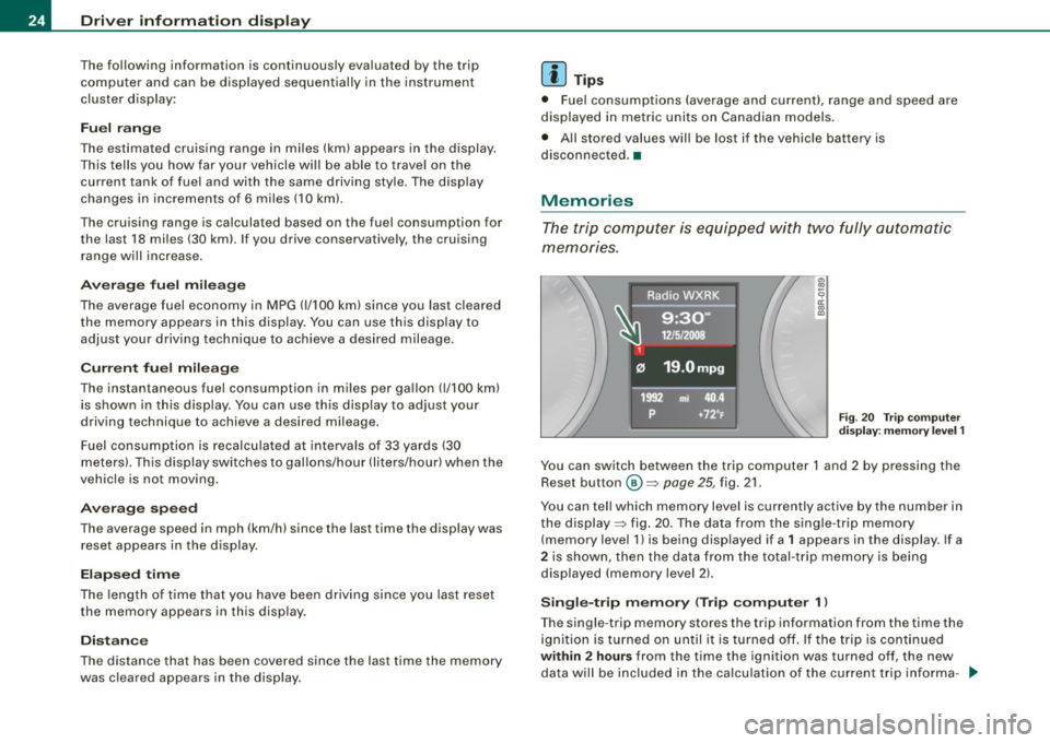
Memori es
The trip computer is equipped with two fully automatic
memories.
Fig . 20 Trip computer
display: memory level 1
You can switch between the trip computer 1 and 2 by pressing the
Reset button
@ ~ page 25, fig . 21.
You can tell which memory level is currently active by the number in
the display ~ fig. 20. The data from the single -trip memory
(memory leve l 1) is being displayed if a
1 appears in the display. If a
2 is shown, then the data from the total-trip memory is being
displayed (memory level 2l.
Single-trip memory (Trip computer 1 l
The single -trip memory stores the trip information from the time the
ignition is turned on until it is turned off. If the trip is continued
within 2 hours from the time the ignition was turned off, the new
da ta will be included in the calculation of the current trip informa -_.,,
Page 27 of 360
tion. If the trip is interrupted for more than 2 hours the memory is
reset automatica lly.
Total-trip memory (Trip computer 2)
Unlike the single-trip memory, the total-tr ip memory is not reset
automatically. This permits you to evaluate your driving data for the
entire period between manual resets. •
Operation
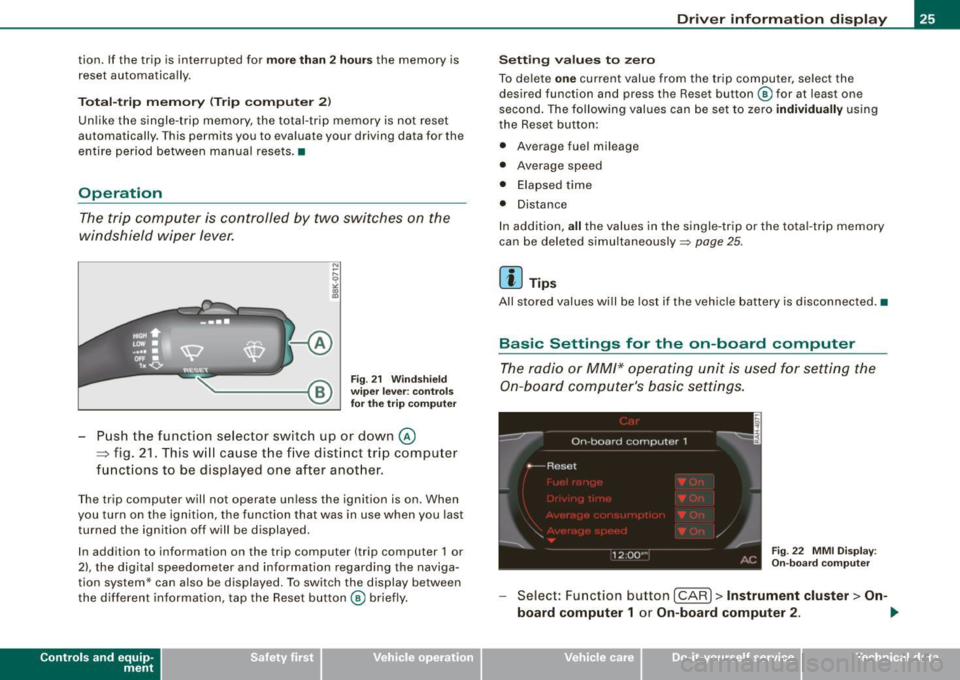
The trip computer is controlled by two switches on the
windshield wiper lever.
Fig. 21 Windshield
wiper lever: controls
for the trip computer
Push the function selector switch up or down@
~ fig. 21. This will cause the five distinct trip computer
functions to be displayed one after another.
The trip computer will not operate unless the ignition is on. When
you turn on the ignition, the function that was in use when you last
turned the ignition off will be displayed.
In addition to information on the trip computer (trip computer 1 or
2), the digital speedometer and information regarding the naviga
tion system* can also be displayed. To switch the display between
the different information, tap the Reset button@ briefly.
Con tro ls and eq uip
ment
Driver information display
Setting values to zero
To delete one current value from the trip computer, select the
desired function and press the Reset button @ for at least one
second . The following values can be set to zero
individually using
the Reset button:
• Average fuel mileage
• Average speed
• Elapsed time
• Distance
In addition,
all the values in the single-trip or the tota l-trip memory
can be deleted simultaneously::::,
page 25.
[ i ] Tips
All stored values will be lost if the vehicle battery is disconnected. •
Basic Settings for the on-board computer
The radio or MM/* operating unit is used for setting the
On-board computer's basic settings.
Fig. 22 MMI Display :
On-board computer
Select: Function button [CAR]> Instrument cluster > On -
board computer 1
or On-board computer 2 . 1iJ,,
Vehicle care I I irechnical data
Page 31 of 360
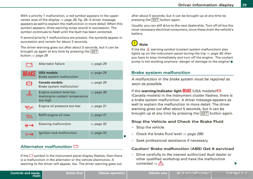
With a priority 1 malfunction, a red symbol appears in the upper
center area of the display=:>
page 28, fig. 26. A driver message
appears as well to explain the ma lfunction in more detail. When this
symbo l appears,
three warning tones sound in succession. The
symbol continues to flash until the fault has been corrected.
If
several priority 1 malfunctions are present, the symbols appear in
succession and remain for about 2 seconds .
T he driver warning goes out after about 5 seconds, but it can be
brought up again at any time by pressing the
I SE T]
button.=:>
page 28
LJ Alternator failure =:> page 29
BRAKE
USA model s: =:> page 29
Brake system malfunctio n
--
Ca nad a mod els: =:> page 29
Brake system malfunction
- F-Engine coolant level too =:> page 30
-low/engine coolant temperature
too high
~ Engine oil pressure too low =:> page 31
~,. Refill engin e oil now =:> page 31
~-e Steering ma lfunction =:> page 32
--
©-e Ignition lock malfunction
=:> page 32
Alternator malfunction 0
If the O symbol in the instrument pane l disp lay flashes, then there
is a malfunction in the alternator or the vehicle electronics. A
warning to the driver will appear, too . The driver warning goes out
Controls and equip
ment
•
Dr ive r informat ion di spl ay
after about 5 seconds, but it can be brought up at any time by
pressing the
ISETj button again .
Usually, you can still drive to the next dea lership . Turn off all but the
most necessary electrical consumers, since these drain the vehicle's
battery .
0 Note
If the the .JL warning symbol (coolant system ma lfunction) also
lights up on the instrument pane l during the trip=:>
page 30, then
you have to stop immediately and turn off the engine . The coolan t
pump is not working anymore --danger of damage to the engine! •
Brake system malfunction
A malfunction in the brake system must be repaired as
soon as possible.
If the warning /indi cator light BRAKE (USA models)/ (©)
(Canada models) in the i nstrument cluster flashes, there is
a brake sys tem mal funct ion . A driver message appears as
well to explain the malfunction i n more detail. T he driver
warning goes o ut after about 5 seco nds, but it ca n be
br ought up a t any time by p ressing the !SET] button aga in .
S top th e Vehi cle and Che ck the Brak e Fluid
- Stop the vehicle.
- Check the brake fluid level=> page
280 .
-Seek professional assistance if necessary .
Cauti on! Brake m alfun ction (ABS ) G et it s ervi ced
- Drive carefully to the nearest authorized Aud i dealer or
other qualified workshop and have the malfunction
corrected =>
&. .,_
I • •
Page 35 of 360
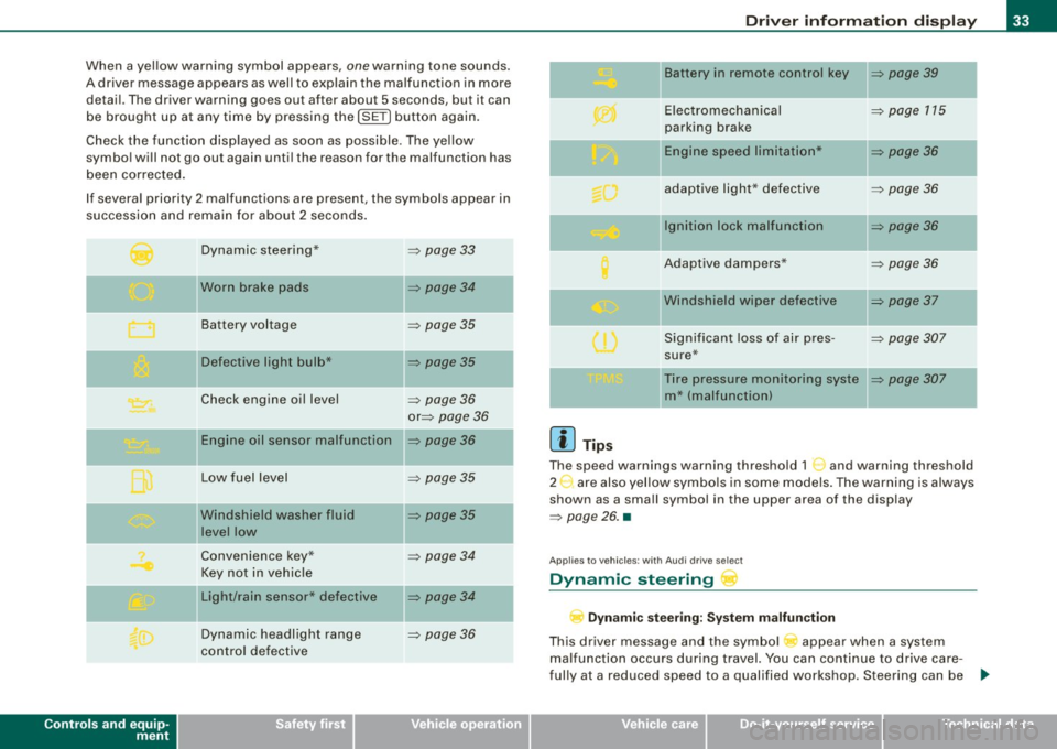
When a yellow warning symbol appears, one warning tone sounds.
A driver message appears as well to explain the malfunc tion in more
detail. The driver warning goes out after about 5 seconds, but it can
be brought up at any time by pressing the
!SE T) button again.
Check the function disp layed as soon as possible . The ye llow
symbol will not go out again until the reason for the malfunction has
been corrected.
If several priority 2 malfunctions are present, the symbols appear in
succession and remain for about 2 seconds .
Controls and equip
ment
Dynamic steering*
Worn brake pads
Battery voltage
II Defective light bulb*
Check engine oil level
Engine oil sensor malfunction
Low fuel level
Windshield washer fluid
level low
Convenience key*
Key not in vehicle
Light/rain sensor* defective
Dynamic headlight range
control defective =>
page 33
=> page 34
=>
page 35
=> page 35
-
=> page 36
or => page 36
=> page36
=> page 35
=> page 35
=> page 34
=> page 34
=> page 36
Dr ive r informat ion di spl ay
II Battery in remote control key => page 39
-
Electromechanical => page 115
parking brake
-Engine speed limitation* => page 36
adaptive light * defective => page 36
Ignition lock malfunction => page 36
Adaptive dampers* => page 36
"Windshield wiper defective => page 37
-
Significant loss of air pres -=> page 307
sure*
Tire pressure monitoring syste
=> page 307
m* (malfunction)
[ i ] Tip s
The speed warnings warning threshold 1 '") and warning threshold
2 :,. are also yel low symbo ls in some models. The warning is always
shown as a small symbol in the upper area of the display
=> page 26. •
Applies t o veh ic les: w ith Audi dri ve sele ct
Dynamic steering
D yn a m ic s te er ing : Syste m malfun cti on
This driver message and the symbol appear when a system
malfunction occurs during travel. You can continue to drive care
fully at a reduced speed to a qualified workshop. Steering can be .,_
I • •
Page 37 of 360
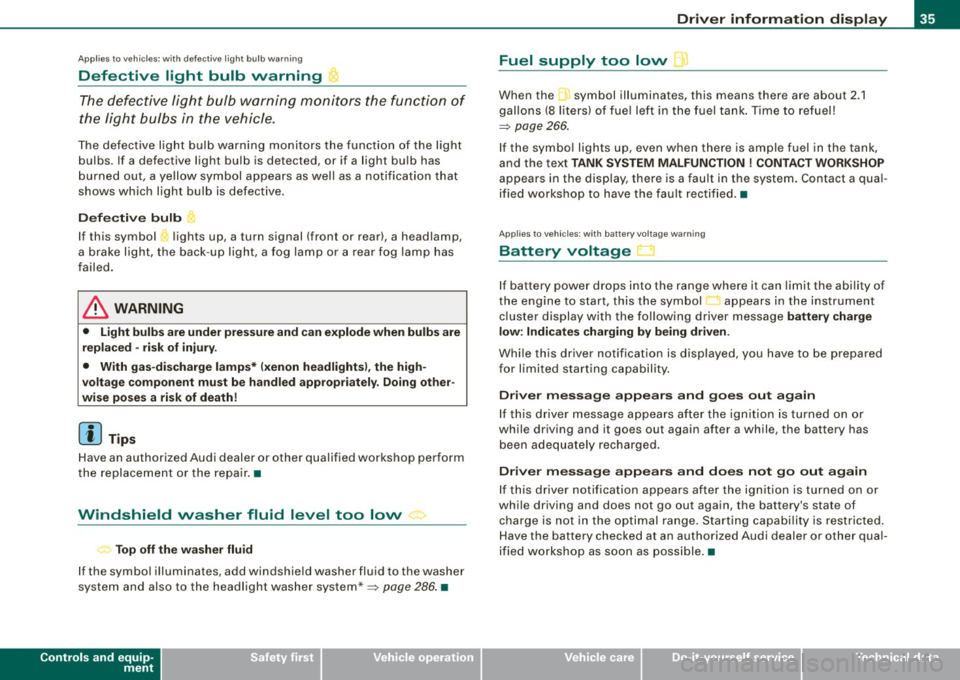
Applies to vehic les: with defective light bulb warn ing
Defective light bulb warning
The defective light bulb warning monitors the function of
the light bulbs in the vehicle.
The defective light bulb warning monitors the function of the light
bulbs. If a defective light bulb is detected, or if a light bulb has
burned out, a yellow symbol appears as well as a notification that
shows which light bulb is defective.
Defective bulb
If this symbol lights up, a turn signal (front or rear), a headlamp,
a brake light, the back-up light, a fog lamp or a rear fog lamp has
failed.
& WARNING
• Light bulbs are under pressure and can explode when bulbs are
replaced -risk of injury.
• With gas-discharge lamps* (xenon headlights), the high
voltage component must be handled appropriately. Doing other
wise poses a risk of death!
[ i] Tips
Have an authorized Audi dealer or other qualified workshop perform
the replacement or the repair. •
Windshield washer fluid level too low ->
Top off the washer fluid
If the symbol illuminates, add windshield washer fluid to the washer
system and also to the headlight washer system* =>
page 286. •
Controls and equip
ment
Driver information display
Fuel supply too low \l
When the symbol illuminates, this means there are about 2.1
gallons
(8 liters) of fuel left in the fuel tank. Time to refuel!
=>
page 266.
If the symbol lights up, even when there is ample fuel in the tank,
and the text
TANK SYSTEM MALFUNCTION ! CONTACT WORKSHOP
appears in the display, there is a fault in the system. Contact a qual
ified workshop to have the fault rectified. •
Applies to veh icles: with battery voltage warning
Battery voltage ..:J
If battery power drops into the range where it can limit the ability of
the engine to start, this the symbol appears in the instrument
cluster display with the following driver message
battery charge
low: Indicates charging by being driven .
While this driver notification is displayed, you have to be prepared
for limited starting capability.
Driver message appears and goes out again
If this driver message appears after the ignition is turned on or
while driving and it goes out again after a while, the battery has
been adequately recharged.
Driver message appears and does not go out again
If this driver notification appears after the ignition is turned on or
while driving and does not go out again, the battery's state of
charge is not in the optimal range. Starting capability is restricted.
Have the battery checked at an authorized Audi dealer or other qual
ified workshop as soon as possible. •
I • •
Page 41 of 360

[ i J Tips
• The operation of the remote control key can be temporarily
disrupted by interference from transmitters in the vicinity of the
vehicle working in the same frequency range {e .g . a cell phone,
radio equipment).
• If you open the driver's door with the key left in the ignition lock,
a chime will sound. This is your reminder to remove the key and lock
the door.
• For security reasons, replacement keys are only available from
Audi dealers.
• For Declaration of Compliance to United States FCC and Industry
Canada regulations~
page 342. •
Check light in the master key
The check light in the master key provides information
about different conditions.
!
lJl
Fig. 29 Check light in
the master key
The check light comes on briefly once when a button is pressed, and
during an "inquiry" by the convenience key system.
Con tro ls and eq uip
ment
Opening and closing
If the check light does not come on, the battery is dead and has to
be replaced. In addition, when the battery is dead the symbol
appears in the instrument cluster display as well as the message :
Please change key battery
Battery replacement ~ page 39. •
Master key battery replacement
..
Fig. 30 Remote master
key: Removing the
mechanical key
Fig . 31 Remote master
key: Removing the
battery holder
We recommend having the battery changed by an autho
rized Audi dealer. However, if you wish to replace the dead
battery yourself, proceed as follows:
- Press the release button @=>fig. 30.
Vehicle care I I Technical data
Page 42 of 360
Opening and closing
- Pull the mechanical key ® out of the master key.
- Press the release button @~page
39, fig. 31 on the
battery holder and at the same time pull the battery
holder out of the master key in the direction of the arrow.
- Install the new battery CR 2032 with the"+" sign facing
down.
- Push the battery holder carefully into the master key .
- Install the mechanical key.
<£> For the sake of the environment
Dispose of dead batteries properly so as not to pollute the environ
ment.
[ i J Tips
The replacement battery must be the same specification as the
original. •
Removing the mechanical key
- Press the release button @~fig. 32.
Fig. 32 Remote master
key : Removing the
mechanical key
- Pull the mechanical key ® out of the master key.
Using the mechanical key , you can
• Lock and unlock * the storag e compartment on the passenger's
side
~ page 89.
• Lock and unlock the lockable rear se at ~ page 82.
• Lock and unlock the vehicle manually~ page 45 if this should
not be possible with the master key .•
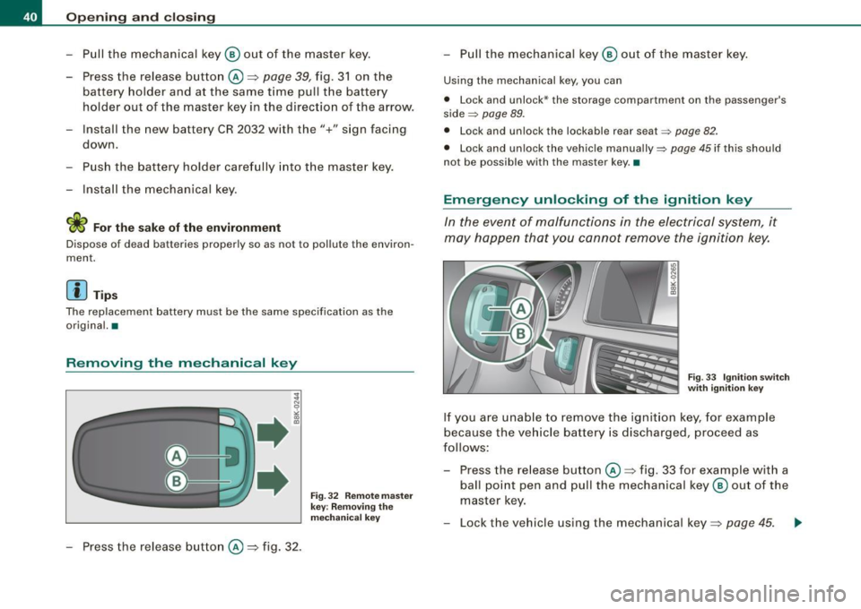
Emergency unlocking of the ignition key
In the event of malfunctions in the electrical system, it
may happen that you cannot remove the ignition key.
Fig . 33 Ignition switch
with ignition key
If you are unable to remove the ignition key, for example
because the vehicle battery is discharged, proceed as
follows:
- Press the release button@~ fig. 33 for example w ith a
ball point pen and pull the mechanical key ® out of the
master key.
- Lock the vehicle using the mechanical key~ page
45. ..,_
Page 47 of 360

-Touch the sensor at the door hand le on ce => page 44,
fig. 39 to lock the vehicle=> & in "Ge neral description"
on
page 41 .
The vehicle can be locked and unlocked at any door. It depends on
the settings in the radio or MM I* whether the entire vehicle is
unlocked or one of the doors =>
page 43. The master key mus t be
within a range of about 1 .5 m from the appropriate door or the rear
lid . It makes no difference whethe r the master key is in your jacket
pocket or in your brief case.
If you grip the door handle while locking, this can adversely affect
the locking funct ion.
It is not possib le to re-open the door for a brief period directly after
closing i t. This allows you to ensure that the doo rs are proper ly
locked.
& WARNING
Read and foll ow all WARNING S => & in "General description " on
page 41 .
[ i ] Tips
If you r vehicle has been s tanding for an extended period, p lease
note the following:
• The proxim ity sensors are deactivated after a few days to save
power. You then have to pull on the door handle once to unlock the
vehic le and a second time to open the vehic le .
• T o prevent the battery from being discharged and to preserve
your vehicle's ability t o start for as long as possible, the energy
management system gradual ly switches off unnecessary conve
nience functions . It is possib le tha t you will not be ab le to unlock
your vehicle using these convenience functions.
• For Declara tion of Compliance to United States FCC and Industry
Canada regulations=>
page 342. •
Controls and equip
ment
Opening and clo sing
Operating locks with the mechanical key
In the event of a failure of the po wer locking system, the
driver's do or can locked and unlocked with the mechan
ical key at the lock cylinder.
To unlo ck the vehicle
~ N 0
"' "' m
Fig . 4 0 Key turns for
o pen ing and clo sing
- Insert t he mec han ica l key into the lock of the driver's
doo r.
- Turn t he mec ha ni ca l key to position @=> fig. 40 .
To lock the vehicle
-Move the selector lever to the P position (automatic
t ra n smission*).
- Close a ll windows and doors proper ly.
- Turn the mec han ica l key in the lock of the dr iver's door to
the lock position
® => & in "Gene ra l description" on
page 41.
If the power locking system fai ls, there is emergency locking for the
passenger's door=>
page 47. ~
I • •