display AUDI A5 COUPE 2010 Owners Manual
[x] Cancel search | Manufacturer: AUDI, Model Year: 2010, Model line: A5 COUPE, Model: AUDI A5 COUPE 2010Pages: 360, PDF Size: 84.39 MB
Page 7 of 360
About this Owner's Manual
This owner's manual contains important information, tips, sugges
tions, and wa rnings for the use of your vehicle.
Make sure that this owner's manual is always located in the vehicle .
This is especial ly important if you a llow other people to drive the
veh icle, or if you sel l it.
T his owner's manual describes the
equ ip me nt r ange specified for
this model at the editoria l deadline date. Some of the equipmen t
described here will only be availab le at a later date, or on ly in
specific markets.
Some sect ions in this owner's manua l do not apply to al l vehicles.
In that case, the
ran ge of a pplica bility is given at the beginning of
the sect ion, e . g ., "Applies to vehicles : with advanced parking
system". In addition, optional equipment is indicated by an asterisk
"*"
The details in the illu strations may be different from those in your
vehicle, and are intended to be viewed as a basic guide .
You wil l find a
table of content s at the beginning of this book , which
displays all topics described in this manua l in order of appearance.
You will f ind an a lphabetical
index at the end of this book.
All
direct ions , such as "left", "r ight", "front", "back", are relative to
the direction of travel.
optiona l equipment
.,.. This section continues on the next page .
• Indicates the
end of a section .
® Registered trademarks are ide ntified with a® . If this symbol is
missing, it is no guarantee that the terms can be used freely .
=> & Cross-reference to a "WARNING!" within a sec tion . For indi
cation with a page number, the corresponding "WARN ING!" can be
f ound outside of the section.
Controls and equip
ment Safety first Vehicle operation
About thi
s Own er's Manual
& WARNING
Te xt w ith th is sy mbol con tains important inf ormation on safet y
and how to redu ce the ri sk of per sonal injury or d eath .
0 Note
Text with this symbo l d raws your attention to po tential sources of
damage to your vehicle.
and how you can help protect it.
[ i ] Tips
Text with this symbo l contains special tips and other information
about getting the mos t out of your vehicle and its features. •
Vehicle care Do-it-yourself service Technical data
Page 9 of 360
Instruments and controls
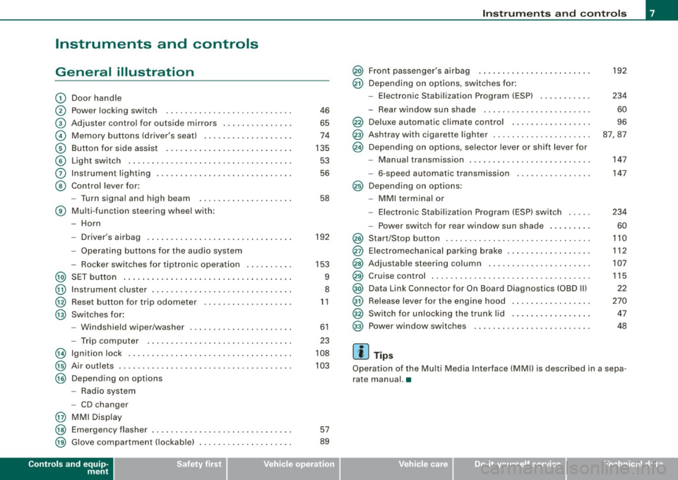
General illustration
G)
0
©
©
©
©
0
©
Door handle
Power locking switch
Adjuster contro l for outside mi rrors .. ...... ...... .
Memory buttons (driver's seat) .. ....... ...... ... .
Button for side assist ..... .... ... .. ...... ... ... .
Light switch .. ...... ....... ... ... .. .... ....... .
Instrument lighting ...... ..... .. .... .... ...... . .
Control lever for :
- Turn signal and high b eam
® Multi -function steering wheel with:
- Horn
-Driver's airbag .... ..... .. .... .... .... .... ... .
- Operating buttons for the audio system
- Rocker swi tches for tiptronic operation ...... ... .
@ SET button ..................... .... .......... .
@ Instrument cluster . ...... ........ .............. .
@ Reset button for trip odometer ... ...... ...... ... .
@ Swi tches for:
@
@
@
@
@
@
- Windshield wip er/washer ............. ... .. ... .
- Trip computer ..... .. .... .... ...... .... ... .. .
Ign ition lock .... .... .... ...... .... ... ... ... ... .
Air ou tlets ........... .... ..... ........... ... .. .
Depend ing on options
- Radio system
- CD changer
MM I Display
Emergency flasher
G love compartment ( lockab le)
Controls and equip
ment
46
65
74
135 53
56
58
192
153
9
8
11
61
23
108
103
57
89
Instruments and controls
@ Front passenger's airbag ......... ... .... .... ... .
@ Depending on options, switches for:
@
@
@
@
@
@
@
@
@
@
@
@
- Elect ron ic Stabilization Program (ESP) ..... .. .. . .
- Rear window sun shade ..... ... ... ... ... .. ... .
Deluxe automatic climate control . .... .... .... ... .
Ashtray with cigare tte lighter ..... ...... .. .... ... .
Depending on options, selector lever or shift l ever for
- Manual transmission ........ .... ....... .. . ... .
- 6-speed automatic transmission
Depending on options:
- MMI terminal or
- Electronic Stabil ization Program (ESP) switch
- Power switch for rear window sun shade ........ .
Start/Stop button .... .... ... .... .... .... .... ... .
Elect romechanical parking brake ... .... .... ...... .
Adjus tab le ste ering column .. ...... ...... ..... .. .
Cruise control .... ... .... .... .... .... .... ... ... .
Data Link Connector for On Board Diagnostics (OBD Ill
Release lever for the engine hood ........ ........ .
Switch for unlocking the trunk lid ...... .... .. .. .. .
Power window switches
[ i ] Tips
192
234
60
96
87,87
147
147
234
60
110
112
107
115
22
270 47
48
Operation of the Mu lti Media Interface (MMll is described in a sepa
rate manual. •
I • •
Page 10 of 360
Instruments and warning /indicator lights
Instruments and warning/indicator lights
Instruments
Instrument cluster and controls
The instrument cluster is your central source of informa
tion .
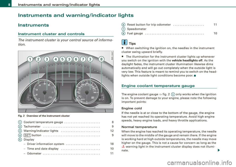
Fig . 2 Overview of the instrument cluster
CD Coolant temperature gauge .................... . .
0 Tachometer .............. ... ........ .... ..... .
G) Warning/indicator lights .. ... .... ... ... ...... .. .
© [ SET ] button .. .... ... ........ .... .. ...... .... . .
© Disp lay
- Driver information system ............. ... .... .
- Time and date display ..... ........ .... .... .. .
- Odom eter .. ............ ... ........ ......... .
8
9
12
9
18
10
11
©
G)
©
Reset button for trip odometer
Speedometer
Fuel gauge ... .... ... ..... .... .... ... .... ... .• .
[ i ] Tips
11
10
• When swi tching the ignition on, the needles in the instrument
cluster swing upward briefly.
• The illumination for the instrument cluster lights up wh en ever
you switch on the ignition with the
vehicle headlights off. As the
dayligh t fades , the instrument cluster illumina tion likewise dims
automatically and wil l go out completely when the outside light is
very low. This feature is meant to remind you to switch on the head
lights when outside light conditions become poor.•
Engine coolant temperature gauge
The engine coolant gauge=> fig . 2 CD only works when the ignition
is on . To prevent damage to your engine , please note the following
important points:
Engine cold
If th e needle is at or close to the bot tom of the gauge, the engine
has not yet reached its operating temperature. Avoid high engine
speeds, heavy engine loads, and heavy throttle app lications.
Normal temperature
When the engine has reached its operating temperature, the needle
will move to the middle o f the gauge and remain ther e. I f t he engine
is working hard at high outside temperatures , the needle may move
higher on the gauge. This is not a cause for concern as long as the
.J L warning light in the instrument cluster display does not illumi -
nate. .,
Page 11 of 360
Warning light in the instrument cluster display -L
If the _L wa rn ing l ight in the ins trument cluste r display flashes, this
can mean one of two things : either the coolant temperature is too
h igh, or the coolan t level is too low ~ page 30.
If t he needle is we ll in the upper area of the gauge, the coolant
temperature is too high.
Stop the vehicle , swit ch the engine off , and
allow it to cool.
If the war ning light comes on again a fter d riv ing a
short distance, contact an authorized Audi dea ler or other qualified
w orksh op.
& WARNING
• Alway s observe the warning in ~ page 263 , "Engine compart
ment ", before open ing the hood and che cking the engine coolant
level.
• Never open the engine hood if you see or hear steam , or if you
s ee engine coolant dripping from the engine compartment. You
could burn yourself . Let the engine cool off first so that you cannot
hear or see any steam or engine coolant .
0 Note
• Mo unting add itiona l lights or accesso rie s in front o f the ai r inlets
reduces the cooling effect of the radiator . At high outside tempera
t ures or high engi ne load, the engine coul d overheat .
• T he front spoiler has been designed to properly distribute the
cooling air wh en the vehic le is m oving. If the spoi ler is dam age d,
this could reduce the coo ling effect and the engine could then over
heat . Ask your a uth oriz e d Audi deale r for assis tance .•
Con tro ls and eq uip
ment
Instruments and warning /indicator lights
Tachometer (engine rev counter)
T h e ta chometer in dicat es th e engine RPM (r e vo lutio ns per
m in ute s).
If engine RPM drops be low 1,500, you should downshift to the next
low er g ear. The red area at t he end o f the scale indicates ma xim um
permissible engine RPM after the break -in period. Before reaching
this ar ea, move the se lecto r lever to pos ition
D (Drive) or ease y our
foot off the acce lerator peda l.
0 Note
The tachometer needle@~ page 8, fig. 2 should only briefly be in
t he red zone : you c oul d da mage y our engine! The beginning of the
red zone varies depending on the engine .
~ For the sake of the environment
Upshiftin g ear ly saves fu el and reduces engine noise .•
[ S ET ) button
Y o u c an pe rform diffe re n t fu nctio ns w ith this but ton.
Fig . 3 SET button in
the in strument clu ster
The [S ET ] b utto n perfor ms the fo llowi ng fu nc tio ns:
Vehicle care I I irechnical data
Page 12 of 360
![AUDI A5 COUPE 2010 Owners Manual Instruments and warning/indicator lights
Switching on time, date, temperature display, and
odometer
The display appears for approximately 30 seconds when you press
the !SET] but AUDI A5 COUPE 2010 Owners Manual Instruments and warning/indicator lights
Switching on time, date, temperature display, and
odometer
The display appears for approximately 30 seconds when you press
the !SET] but](/img/6/57582/w960_57582-11.png)
Instruments and warning/indicator lights
Switching on time, date, temperature display, and
odometer
The display appears for approximately 30 seconds when you press
the !SET] button =>
page 9, fig. 3 with the ignition off.
Starting the Auto-Check sequence
The Auto -Check system => page 27 constantly monitors certain indi
vidual functions and components of the vehicle when the ignition is
turned on and when the vehicle is moving.
With the ignition turned on, you can start the "Auto-Check
sequence" by pressing the !SET ] button . You can perform an Auto
Check sequence when the vehicle is stationary and the ignition is
turned on or when the vehicle is moving slower than 3 mph (5 km/hl.
Calling up the driver information
A yellow or red symbol appears in the instrument cluster display,
usually with a driver message. The driver message display disap
pears after about 5 seconds. The driver message can be displayed
again by briefly pressing the !SET] button.
Setting the speed warning
By pressing the [SET] button briefly, you can set threshold 1 of the
speed warning while you are driving=>
page 26. By maintaining
pressure on the !SET] button, you delete the warning threshold. •
Digital clock with date display
Digital clock
Fig. 4 Instrument
cluster: time and date
The date, time of day, time and date format can be set in the radio
or MMI*. You can learn more about this in the MMI manual or in the
radio user's manual.
[ i] Tips
• The digital clock turns on for about 30 seconds when the driver's
door is opened.
• When the ignition is turned off, the odometer reading and the
digital clock with date display can be switched on for about
30 seconds by pressing the !SET] button =>
page 9, fig. 3. •
Fuel gauge
The fuel gauge works only when the ignition is on.
When the needle reaches the red area, the warning light in the
instrument cluster will illuminate=>
page 35 . This means you
have approximately 2.1 gallons (8 liters) of fuel left in the tank.
Time
to refuel!
The total tank capacity of your vehicle is listed in=> page 337. .,,
Page 13 of 360
0 Note
Never run the tank completely dry! An irregular supply of fuel can
cause engine misfiring and fuel could enter into the exhaust
system. The cata lytic converter could then overheat and be
damaged .•
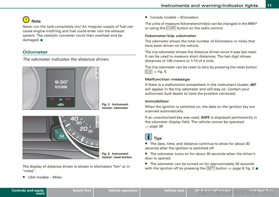
Odometer
The odometer indicates the distance driven.
Fig. 5 Instrument
cluster: odometer
Fig . 6 Instrument
c luste r: reset button
The display of distance driven is shown in kilometers "km" or in
"miles".
• USA models -Miles
Con tro ls and eq uip
ment
Instruments and warning /indicator lights
• Canada models - Kilometers
The units of measure (kilometers/miles) can be changed in the MMI*
or using the
I CAR I button on the radio control.
Odometer/trip odometer
The odometer shows the total number of kilometers or miles that
have been driven on the vehicle .
The trip odometer shows the distance driven since it was last reset.
It can be used to measure short distances. The last digit shows
distances of 100 meters or 1/10 of a mile.
The trip odometer can be reset to zero by pressing the reset button
[ 0.0] => fig. 6.
Malfunction message
If there is a malfunction somewhere in the instrument cluster,
dEF
will appear in the trip odometer and will stay on . Contact your
authorized Audi dealer to have the problem corrected.
Immobilize r
When the ignition is switched on, the data on the ignition key are
scanned automatically .
If an unauthorized key was used,
SAFE is displayed permanently in
the odometer disp lay field. The vehicle cannot be operated
=> page 38.
[ i ] Tips
• The date, time, and distance cont inue to show for about 30
seconds after the ignition is switched off.
• The odometer turns on for about 30 seconds when the driver's
door is opened .
• The odometer can be turned on for approximate ly 30 seconds
with the ignition off by pressing the [SET ] button=> page 9, fig. 3. •
Vehicle care
I I irechnical data
Page 15 of 360
& WARNING
• Failure to heed warning lights and other important vehicle
information may result in serious personal injury or vehicle
damage .
• Whenever stalled or stopped for repair, move the vehicle a safe
distance off the road, stop the engine, and turn on the emergency
flasher =>
page 57.
• The engine compartment of any motor vehicle is a potentially
hazardous area. Before you check anything in the engine compart
ment, stop the engine and let it cool down . Always exercise
extreme caution when working under the hood =>
page 263,
"Engine compartment ".
[ i] Tips
Many functions are monitored by the Auto-Check system
=>
page 27. Malfunctions or faults will be identified either with a red
symbol (priority 1 -Danger!) or with a yellow symbol (priority 2 -
Warning). •
Applies to vehic les: with Audi dr ive select
Dynamic steering c
If the indicator light illuminates when switching on the ignition
and goes out when the engine starts, dynamic steering is activated.
If the indicator light '.,,; illuminates after the engine starts, a system
malfunction has occurred. You can continue to drive carefully at a
reduced speed to a qualified workshop. Steering can be more diffi
cult or sensitive than usual. The steering wheel may also be at an
angle when driving straight.
Controls and equip
ment
Instruments and warning/indicator lights
& WARNING
Have the dynamic steering system malfunction repaired as soon
as possible by an authorized Audi dealer or any qualified work
shop -risk of accident!
[ i] Tips
• If the indicator light 6 flashes, dynamic steering is being re
initialized. The driver information system display shows the words
"Dynamic steering: initialization"=>
page 33.
• The dynamic steering stability systems are not available in the
event of a system malfunction. •
Electronic power control r.
This warning/indicator light monitors the electronic
power control.
The warning/indicator light (Electronic Power Control) illumi-
nates when you turn on the ignition as a function check.
[ i] Tips
If this warning/indicator light illuminates while you are driving, then
there is a malfunction in the engine electronics . Have the malfunc
tion corrected as soon as possible by your authorized Audi dealer or
qualified workshop. •
Electronic stabilization program (ESP)
If the ~ indicator lamp blinks while driving, the ESP or ASR (Anti
Slip Regulation) is actively regulating.
If the indicator lamp illuminates, the system has switched the
ESP off. In this case, you can switch the ignition off and then on to .,_
I • •
Page 18 of 360
Instruments and warning/indicator lights
Malfun cti on in the ele ctronic differ ential lo ck (EDL )
The
ED L works t oget her with the ABS. T he ABS warning light w ill
come on if there is a ma lfunction in the
ED L system=> page 235 . See
your au thorized A ud i dea ler as soon a s possible.
& WARNING
• If the ,..,1 (USA models )/;:_,,. (Canada models) warning light
does not go out , or if it comes on while driving , the ABS system is
not working properly. The vehicle can then be stopped only with
the standard b rake s (w ithout ABS ). You will not have the p rotec
tion ABS provides. Contact your authorized Audi dealer as soon as
po ssible .
• USA model s: If the BRAKE warning light and the l:i warning
light come on together, the rear wheel s could lock up first under
hard braking . Rear wheel lock-up can cause lo ss of vehicle control
and an ac cident. Have your vehicle repaired immediately by your
authori zed Audi dealer or a qualified workshop . Dr ive slowly and
avoid sudden , hard brake applications .
• Canada models : If the brake warning light «I» and the ABS
warning light
~ come on together , the rear wheels could lock up
first under hard braking . Rear wheel lock-up can cause loss of
vehicle control and an accident. Have your vehicle repaired imme
d iately by your authorized Audi dealer or a qualified workshop .
Drive slowly and avoid sudden , hard brake applications. •
Electromechanical parking brake
~[ (USA models) /(®) (Canada models)
The wa rning/in dic at or l ight m oni tors the elec tromechan
i c a l p arkin g bra ke.
With the parking brake applied and the ignit ion turned on, the
war ning/ ind icator lig ht illu min a te s. After the ig nition has been
turned off, the warning/indicator light continues to i llum inate for
abo ut 3 0 seconds. If the parking bra ke is applied with the ignition turned off, the warning/indicator light i
lluminates for about 30
s e co nd s.
Th e warning/ind icator light wi ll go out when the parking brake is
r eleased .
I f the warn ing/indica tor l ight flas hes con tinuously
after applying the
par king brake, bra king force is not sufficient to prevent the vehicle
from rol lin g uninten tiona lly . Please n ote the fo llowing:
• I f the slope of the ground is too steep to park the vehicle, the
additiona l drive message a ppea rs
Caution: Vehicle parked too
steep .
• In the event of a pa rking brake ma lfunction, the yel low symbol
appears in the instrument c luster display and the driver message
Parking brake malfunction! is displayed . Have the malfunction
r epaired as soon as possib le by an aut hor ized Audi dea ler or any
other qua lified workshop. •
Brake system BRAKE (USA models) /((D) (Canada
models)
The warning/indicator light fl ashes if bra ke fluid level is
low, if there is an A BS sys tem mal function or a parking
brake malfun ctio n.
T he li ght illu minates w hen t he ignitio n is tur ned on. It goes out afte r
the engine has been started . T his indicates that the brake warning
li ght is fu nctioni ng prope rly.
l9 If the brake warning l ight does not lig ht up when the eng ine is
cranking , there may be a malfunction in the electrical system. In this
case , contact an authori zed Audi dealer .
If the brake system warning/indicator light flashes, there is a brake
system ma lfunc tion . By press ing t he
[SE T) button, you ca n brin g up
a driver message which explains the ma lfunction in more detai l
=>
p age 29. ~
Page 20 of 360
Driver informati on displ ay
Driver information display
Introduction
General notes
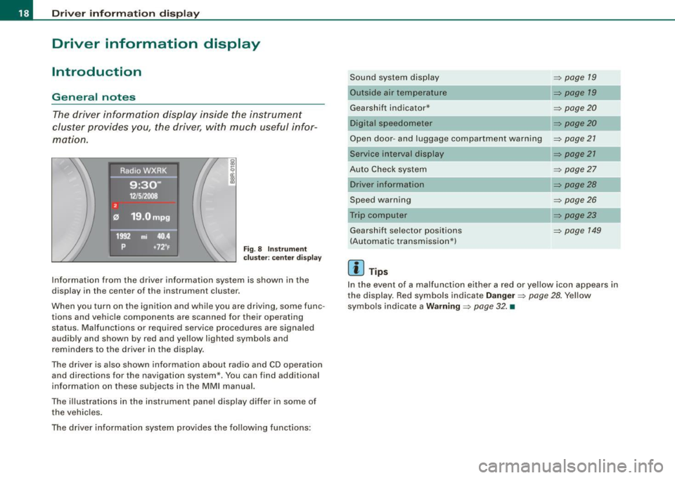
The driver information display inside the instrument
cluster provides you, the driver, with much useful infor
mation.
Fig . 8 Inst rum ent
c lu ster : cente r dis pl ay
Informat ion from the driver information system is shown in the
display in the center of the instrument cluster.
When you turn on the ignition and while you are driving, some func
tions and vehicle components are scanned for their operating status. Malfunctions or required service procedures are signaled
audibly and shown by red and yellow lighted symbols and
reminders to the driver in the display.
The driver is also shown information about radio and CD operation and directions for the navigation system *. You can find additional
information on these subjects in the MMI manual.
The illustrations in the instrument panel display differ in some of
the vehicles.
The driver informat ion system prov ides the following functions: Sound sys
tem display ::::;,
page 19
Outside air temperature ::::;, page 19
Gearshift indicator* _________ ::::;, page 20
Digital speedometer ::::;, page 20
Open door- and luggage compartment warning ::::;, page 21
Service interval display
Au to Check syst em
Driver information
Speed warning
Trip computer Gearshift selector positions
(Automatic transmission*)
[ i ] Tips
::::;, page 21
::::;, page27
::::;, page28
::::;, page26
::::;, page23
::::;, page 149
In the event of a malfunction either a red or yellow icon appears in
the display. Red symbols indicate
D anger ~ page 28. Yellow
symbols ind icate a
Warning ::::;, page 32. •
Page 21 of 360
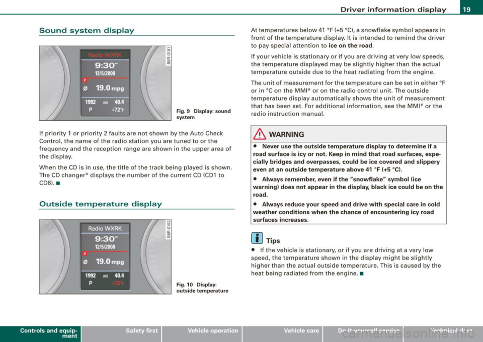
Sound system display
Fig. 9 Di spla y: s ound
system
I f priority 1 or priority 2 faults are not shown by th e Auto Check
Co ntro l, the name of the ra dio s ta tion yo u are tune d to or the
frequency and the reception range are shown in the upper area of
t he d isplay .
Whe n th e CD is i n use , the title of t he track bei ng p layed is shown .
T he CD changer * displays th e number of the current CD (CD 1 to
CD6l . •
Outside temperature display
Con tro ls and eq uip
ment
Fig . 10 Disp lay:
out side temper atu re
Driver information display
At temperatures be low 41 °F (+5 °C), a snowflake symbol appears in
fr ont of t he te mp eratur e dis play . It is inte nded to remind the d river
to pay special attent ion to
ice on the road.
If your vehicle is stationa ry or if you are d riving at very low speeds,
th e te mpera ture d isplaye d may b e slig htly h igher t han the actu al
temperature outside due to the heat radiating from the engine.
The unit o f measu rement for the temp erature ca n be set in eit her °F
or in °Con the MM I* or on the radio control unit . The outside
tempe rature display a utoma tical ly sh ows the unit of meas urement
that has been set. For additional information , see the MM I* or the
r adi o ins tructi on manual.
& WARNING
• Never use the outside temperature display to determine if a
road surfa ce is icy or not . Keep in mind that road surfa ces , espe
cially bridges and overpasses, could be ice covered and slippery
even at an outside temperature above 41
° F (+5 °C ).
• Always remember, even if the "snowflake " symbol (ice
wa rning) does not appear in the display , black ice could be on the
road .
• Always reduce your speed and drive with special care in cold
weather conditions when the chance of encountering icy road surfaces in creases .
[ i ] Tip s
• I f the vehic le is stationary , or if you are driving at a very low
speed, the temperature shown in the d isplay migh t be slightly
h ig her than the actual outside temperature. This is caused by the
heat being radia ted from the engine .•
Vehicle care I I irechnical data