tow AUDI A5 COUPE 2011 Owner's Guide
[x] Cancel search | Manufacturer: AUDI, Model Year: 2011, Model line: A5 COUPE, Model: AUDI A5 COUPE 2011Pages: 362, PDF Size: 84.88 MB
Page 301 of 362
________________________________________________ T_i_r _e _s _ a_n _ d_ w_ h_ e _ e_l_s __ _
& WARNING (co ntinued )
• Only when all tire s on the vehicle are filled to the correct pre s
sure, the tire pressure monitoring sy stem* can work correctly .
• The u se of incorrect tire pressure values can lead to accidents or
other damage. Therefore it is essential that the driver observe the
specified tire pressure values for the tires and the correct pres
sures for the function of the tire pre ssure monitoring system *.
• Always inflate tires to the recommended and correct ti re pre s
sure before driving off.
• Driving with underinflated tire s bend more , letting them get
too hot resulting in tread separat ion, sudden tire failure and loss
of control.
• Excessive speed and /overload ing can cause heat build-up ,
sudden tire failure and loss of control.
• If the tire pressure is too low or too high , the tires will wear
prematurely and the vehicle will not handle well.
• If the tire is not flat and you do not have to change a wheel
immediately, drive at reduced speed to the neare st service station
to check the tire pressure and add air as requ ired.
0 Note
Dr iv ing without valve stem caps can cause damage to the tire valves.
T o preven t this, a lways make su re t hat fac tory ins talle d va lve stem
caps on all wheels a re securely mo unted on the valve.
'£> For the sake of the environment
Under inflated t ires will a lso increase the fuel consumption .•
Tires and vehicle Load Limits
T here are lim its to the amount of load or we ight that any vehicle a nd
any t ire can c arry . A veh icle t hat is over loaded w ill not hand le well an d
Safety first
is more difficult to stop . Overloading can not only lead to loss of
veh icle co ntro l, bu t ca n also d amage important p art s o f the ve hicl e
and can lead to sudden ti re failure, including a blowout and sudden
deflation that can cause the vehicle to crash.
Your safety a nd tha t of you r passe ngers also depe nds o n mak ing s ure
that load limits are not exceeded. Vehicle load incl udes everybody
and everyt hing in and on t he ve hicle. T hese lo ad lim its are techn ic a lly
referred to as the vehicle's
Gross Vehicle Weight Rating ("GVWR").
Th e "GVWR" includes the weight of the basic vehi cle, all facto ry
installed accessories, a fu ll tank of fue l, o il, coo la nt and other fluids
plus maxim um loa d. Th e maxim um loa d includes t he nu mber of
passeng ers th at t he ve hicl e is intended to car ry ("sea ting capa city ")
with an ass umed weig ht of 150 lbs . (68 kg) for each passenger at a
design ated seating posit ion a nd the to tal weig ht of any luggage in
the vehicle. If yo u tow a tra iler, the weight of the trailer hitch and the
t ongue weig ht of the lo ad ed t railer mus t be include d as pa rt of the
vehicle load.
Th e
Gross Axle Weight Rating ("GAWR") is the maximum load that
can be a pplied at each of t he ve hicle's two axles .
The Gross Vehicle We ight Rating and the Gross Ax le We ight Rating
are li sted on the safety comp lia nce s tick er label loca ted either on the
dr ive r's side B-pilla r o r on the inside of the fuel filler flap . Aud i has
4 se ating posi tions, 2 in the fron t and 2 in the rea r for tot al s eating
capacity of 4. Each seating position has a seat belt~
page 181,
"Safety be lts".
Th e fact t hat there is an upper lim it to your v eh icle 's Gross Vehicle
Weight Rating means that t he tota l weight of whatever is being
c a rried in th e veh icle ( in cl ud ing the w eight of a t railer hitch and the
tongue weight of the loaded tra iler) is limited. The mo re passengers
in the veh icle or p assengers who are heavier th an the sta ndar d
we ights assumed mean that less we ight can be carried as luggage.
Th e ti re pressure label on yo ur Audi also lis ts th e maxim um combined
we ight of all of the occupants and luggage or other cargo that the
vehicle can car ry. For the location o f the labe l~
p age 2 95, fig . 21 2. ~
Vehicle care Technical data
Page 303 of 362
_________________________________________ T_ i_re _ s_a _n_ d_ w_ h_e _e _l_s _ ..... fflll
5. Determine the combined weight of
luggage and cargo being loaded on the
vehicle. That weight may not safely
exceed the available cargo and luggage
load capacity calculated in Step 4.
6. If your vehicle will be towing a trailer,
load from your trailer will be transferred
to your vehicle. Consult this manual to
determine how this reduces the available
cargo and luggage load capacity of your
vehicle.
Check the tire sidewall(~
page 303~
fig. 216) to determine the designated
load rating for a specific tire .•
Vehicle OP-eration
Tire service life
The service life of tires depends on a lot of different
things including proper installation and balancing,
correct tire pressure and driving style .
(-----~
_____ __,,:)
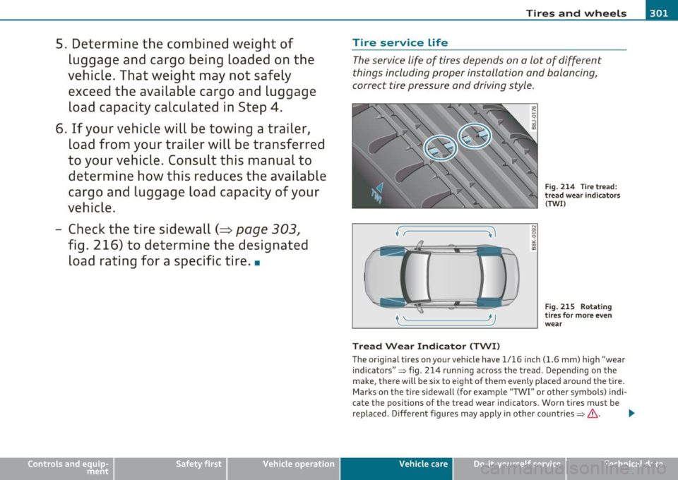
Tread Wear Indicator (TWI)
N
"' 0 9
"" ~
Fig. 214 Tire tread:
tread wear indicators
(TWI)
Fig. 215 Rotating
tires for more even
wear
Th e original tires on your vehicle have 1/16 inch (1.6 mm) high "wear
indicators "~ fig. 214 running across the tread. Depending on the
make, there will be six to eight of them even ly placed around the tire.
Marks on the tire sidewall (for example "TWI" or other symbols) indi
cate the positions of the tread wear indicators. Worn tires must be
rep laced. Different figures may apply in other countries ~
&- .,_
Vehicle care Do-it-yourselt service iTechnical data
Page 316 of 362
-L~W~h~a~t~d~o~I~d~o~n~o~w~? :_ _________________________________________ _
What do I do now?
Vehicle tool kit
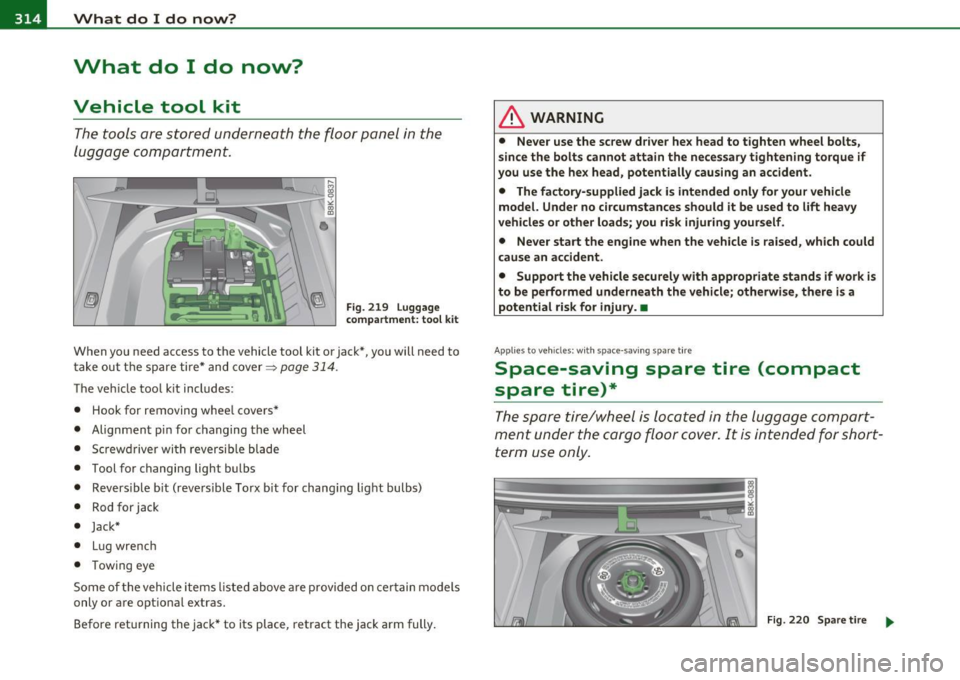
The too ls are stored underneath the floor panel in the
luggage c ompartment.
Fi g. 2 19 Lu ggag e
c om partm ent : too l k it
When you need access to the vehicle tool kit or jack* , you will need to
t ake out t he spare ti re* and cover~
page 314.
The ve hicle too l kit includes:
• Hook for removing whee l covers *
• Alignmen t pin fo r changing the wheel
• Screwdriver wi th reversib le blade
• Tool for changing light bulbs
• Revers ib le b it (reve rs ible To rx bit for chang ing lig ht bulbs)
• Rod for jack
• Jack*
• Lu g wre nc h
• Towing eye
Some of the veh icle items listed above a re p rovided o n cert ain mo dels
only or are opt ional extras.
Before ret urning the jack* to its place, retract the jack arm fully.
& WARNING
• Never u se the screw dri ver he x head to tighten wheel bolts,
s in ce the bolts cannot attain th e neces sa ry tightening torque if
you use the he x head , potent ially caus ing an accident.
• The fa ctory-supplied jack i s intended only for your vehicle
model. Unde r no circumstances should it be used to lift heavy
vehicles or other loads ; you risk injuring you rself .
• Never start the engine whe n the vehicle is raised , which could
caus e an acci dent .
• Support the vehicle securely with appropriate stands if work is
to be performed underneath the vehicle; otherwise , there is a
potential risk for injury. •
App lies to vehicles : w ith space -saving spa re t ire
Space-saving spare tire (compact
spare tire)*
The spare tire/wheel is located in the lugg age comport
ment under the cargo floor cover . It is intended for short
te rm use only.
Fi g. 2 20 S pare t ir e _.,,
Page 318 of 362
lffll.___W __ h_a_ t_ d_ o_ I_ d_o_ n_ o_w _ ? _____________________________________________ _
Changing a wheel
Before changing a wheel
Observe the following precautions for your own and your
passenger's safety when changing a wheel.
- After you experience a tire failure, pull the car well away
from moving traffic and try to reach
level ground before
you stop
~ & .
- All passengers should
leave the car and move to a safe
location (for instance, behind the guardrail)~& .
- Engage the
parking brake to prevent your vehicle from
rolling unintentionally~ &.
- Shift into
1st gear on vehicles with manual transmission,
or move the
selector lever to the P position on vehicles
with automatic transmission*.
- If you are towing a trailer: unhitch the trailer from your vehicle.
- Take the
jack~ page 314 and the spare tire~ page 314
out of the luggage compartment.
& WARNING
You or your passengers could be injured while changing a wheel if
you do not follow these safety precautions:
• If you have a flat tire, move a safe distance off the road. Turn
off the engine, turn the emergency flashers on and use other
warning devices to alert other motorists.
• Make sure that passengers wait in a safe place away from the
vehicle and well away from the road and traffic.
& WARNING (continued)
• To help prevent the vehicle from moving suddenly and possibly
slipping off the jack, always fully set the parking brake and block
the wheel diagonally opposite the wheel being changed with the
folding chocks or other objects. When one front wheel is lifted off
the ground, placing the Automatic Transmission in "P" (Park) will
not prevent the vehicle from moving.
• Before you change a wheel, be sure the ground is level and
firm. If necessary, use a sturdy board under the jack.
• After installing the inflatable spare tire, make sure that you
replace the flat tire/wheel in its storage area properly and tighten
the knurled retaining screw securely.
0 Note
If you are changing the wheel on a steep incline, use a rock or simila r
object to block the opposite wheel to prevent the vehicle from
moving.
[ i] Tips
Obey all laws. •
Changing a wheel
When you change a wheel, follow the sequence described
below step-by-step and in exactly that order.
1. Remove the decorative wheel cover* or the wheel bolt
caps* .
For more details see also~ page 317, "Decorative
wheel covers" or~
page 318, "Wheels with wheel bolt
caps".
2. Loosen the
wheel bolts~ page 318. .,_
Page 330 of 362
lffll.___E_ m_ e_ r-' g=- e_n_ c=-y _ s_it _ u _ a_t_ i_ o _ n_ s ______________________________________________ _
Emergency situations
General
This chapter is intended for trained emergency crew s and working
pe rsonnel who have the necessary tool s and equipment to perform
the se operation s. •
Starting by pushing or towing
0 Note
Veh icles with an automatic transmission cannot be started by
pushing or towing .•
Starting with jumper cables
If necess ary, the engine can be started b y connectin g it to
t he bat tery of another vehicle.
If the e ng ine shou ld fa il to start because of a discharged or weak
battery, the batte ry can be connected to t he battery of
another
veh icle, us ing a pair of jump er cables to start t he eng ine .
Jumper cables
Use only jumper cables of suffic iently large cross section to carry the
sta rter cur rent s afely . Refer to the m an ufa ct ur er's specificat ions.
Use only j umpe r cab les with
insulated te rmi nal clamps wh ich are
distinct ly marked :
plu s(+) cable i n most cases colored red
minus (-) cable i n most cases colored black .
& WARNING
Batterie s contain el ectricity, acid, and gas . Any of the se can cause
very serious or fatal injury. Follow the inst ructions below for safe
handling of your vehicle 's battery.
• Always shield your eyes and avoid leaning over the battery
whenev er po ssible .
• A discharged battery can freeze at temperatures just below
32 °F (0 °C ). Before connecting a jumper cable, you must thaw the
frozen battery completely, otherwise it could explode.
• Do not allow battery acid to contact eyes or sk in . Flush any
contacted area with water immedi ately .
• Improper use of a booste r battery to start a vehicle may cause
an explosion .
• Vehicle batteries generate e xplosive gases. Keep sparks, flame
and lighted cigarettes away from batterie s.
• Do not try to jump start any vehicle with a low acid level in the
battery.
• The voltage of the booster battery must also have a 12-Volt
rating. The capacity (Ah) of the booster battery should not be
lower than that of the discharged battery . Use of batteries of
different voltage or substantially different "Ah " rating may cau se
an e xplosion and personal injury.
• Never charge a frozen battery . Gas trapped in the ice may cause
an explosion.
• Never charge or use a battery that has been frozen. The battery
case may have be weakened .
• Use of batteries of different voltage or substantially different
capacity (Ah) rating may cause an explosion and injury . The
capacity (Ah) of the booster battery should not be lower than that
of the discharged battery. .,_
Page 333 of 362
Emergency situations Ill -------------=---:.-----J
battery that is being charged does not vent to the outside, escaping
battery gas could ignite and explode!•
Emergency towing with
commercial tow truck
General hints
Your Audi requires special handling for towing.
The following information is to be used by commercial tow truck
operators who know how to operate their equipment safely .
• Never tow your Audi, towing will cause damage to the engine
and transmission.
• Never wrap the safety chains or winch cables around the brake
lines.
• To prevent unnecessary damage, your Audi must be transported
with a flat bed truck.
• To load the vehicle on to the flat bed, use the towing loop found
in the vehicle tools and attach to the front or rear anchorage
~ page 331 and ~ page 332.
& WARNING
A vehicle being towed is not safe for passengers. Never allow
anyone to ride in a vehicle being towed, for any reason. •
Vehicle OP-eration
Front towing Loop
Do not install the front towing loop until it is needed.
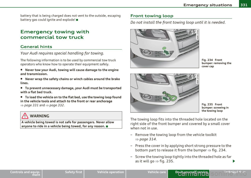
Fig. 234 Front
bumper: removing the
cover cap
Fig. 235 Front
bumper: screwing in
the towing loop
The towing loop fits into the threaded hole located on the
right side of the front bumper and covered by a small cover
when not in use.
- Remove the towing loop from the vehicle toolkit
=> page 314.
- Press the cover in by applying short strong pressure to the
bottom part to release it from the bumper=> fig. 234.
- Screw the towing loop tightly into the threaded hole as far
asitwillgo=,,fig.235.
~
Vehicle care Do-it-yourself service iTechnical data
Page 334 of 362
-Emergency situations PW.__-=----='----------------
When it is no longer needed, unscrew the towing loop and put it back
into the vehicle toolkit. Be sure to have the towing loop stored in the
vehicle at all times.
& WARNING
If the towing loop is not screwed in as far as it will go, the thread
can pull out when the vehicle is towed· potential risk of an
accident. •
Rear towing loop
Do not install the rear towing loop until it is needed.
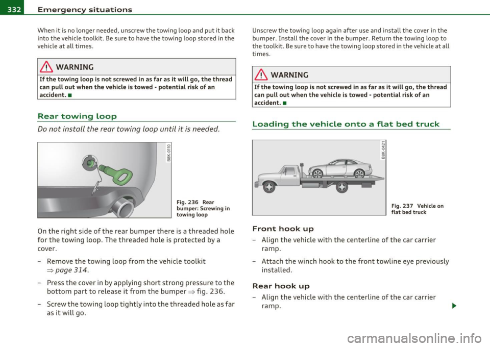
Fig. 236 Rear
bumper: Screwing
in
towing loop
On the right side of the rear bumper there is a threaded hole
for the towing loop. The threaded hole is protected by a
cover.
- Remove the towing loop from the vehicle toolkit
=> page 314.
-Press the cover in by applying short strong pressure to the
bottom part to release it from the bumper => fig. 236.
- Screw the towing loop tightly into the threaded hole as far
as it will go.
Unscrew the towing loop again after u se and install the cover in the
bumper . Install the cover in the bumper. Return the towing loop to
the toolkit. Be sure to have the towing loop stored in the vehicle at all
times.
& WARNING
If the towing loop is not screwed in as far as it will go, the thread
can pull out when the vehicle is towed · potential risk of an
accident. •
Loading the vehicle onto a flat bed truck
Front hook up
Fig. 237 Vehicle on
flat bed truck
-Align the vehicle with the centerline of the car carrier
ramp.
- Attach the winch hook to the front towline eye previously
installed.
Rear hook up
- Align the vehicle with the centerline of the car carrier
ramp.
Page 335 of 362
![AUDI A5 COUPE 2011 Owners Guide Emergency situations --------------=---:.--___.EWI
-Attach the winch hook to the rear tow line eye previously
installed .
[I] Tips
Check carefu lly to make sure the hook -up is secu AUDI A5 COUPE 2011 Owners Guide Emergency situations --------------=---:.--___.EWI
-Attach the winch hook to the rear tow line eye previously
installed .
[I] Tips
Check carefu lly to make sure the hook -up is secu](/img/6/57583/w960_57583-334.png)
Emergency situations --------------=---:.--___.EWI
-Attach the winch hook to the rear tow line eye previously
installed .
[I] Tips
Check carefu lly to make sure the hook -up is secure befo re moving the
car up the flatbed truck ramp. •
Lifting vehicle
Lifting with workshop hoist and with floor
jack
The vehicle may only be lifted at the lifting points illus
tr ated.
Fig . 23 8 F ront lifting
p oi nt
Vehicle OP-eration
Fig. 239 R ear li fting
p oint
- Read a nd hee d W AR NIN G ~ & .
- Lo cat e lift in g points ~ fig . 2 38 and ~ fig. 239.
- Adjust lifting arms o f worksho p hoist or floo r jac k to
ma tc h vehicle li fting poin ts.
- Inse rt a rub ber pad between the floor jack/wor ks h op hoist
an d the liftin g points.
If you must lift your vehicle with a floo r jack to work underneath,
be sure the vehicle is safely supported on stand s intended for this
purpose.
Front Lifting point
T he lifting point is located on the floor pan re inforcement about at
the same level as the j ack mou nting poin t::> fig. 23 8.
Do not lift the
vehicle at the vertical sill reinforcement.
Rear lifting point
The lifting point is located on the vertical reinforcement of the lower
s ill for the onboar d jack ::> fig. 239.
Lifting with vehicle jack
Refe r to::> page 319 .
Vehicle care Do-it-yourself service iTechnical data
Page 342 of 362
___ C_ o_n_ s _ u_m_ e_ r_ I_ n_ f_o _r_ m_ a_ t_io _ n _____________________________________________ _
Consumer Information
Warranty coverages
Your Audi is cov ered by the following warrantie s:
• New Vehicle Limited Warranty
• Limited Warranty Against Corrosion Perforation
• Emissions Control System Warranty
• Emissions Performance Warrant y
• California Emissions Control Warranty (USA vehicles only)
• California Emissions Performance Warranty (USA vehicles only)
Detailed informa tion regarding your warran ties can be fo und in your
Warranty & Maintenance boo klet .•
Operating your vehicle outside the
U.S.A. or Canada
Government regulat ions in the United States and Canada req uire t hat
au tomobiles meet spe cific emi ss ion regula tions and safe ty s tan
dards . There fore, ve hicles bui lt for the U.S.A . and Canada differ from
vehicles so ld in othe r countries.
If you plan to take your vehicle ou tside the continental lim its of the
United States or Canada, the re is the possibility that
• unle aded fue ls for vehicle s w ith c ataly tic converte r may n ot be
available;
• fue l may have a conside rably lower octa ne rat ing . Imp roper f ue l
may cause engine damage;
• serv ice may be inadequate due to lack of proper serv ice fac ilities,
too ls or testing eq uipment;
• replacement parts may not be read ily avai lab le . • N
avigation syst ems for veh icles built fo r th e U.S.A. and Canada
w ill not necessar ily work in Europe, and may not wo rk in other coun
tries outside of North Ame ric a.
0 Note
Audi canno t be responsib le for mech anical dam age th at could res ult
from inadeq uate fue l, se rvice o r parts ava ilability. •
Audi Service Repair Manuals and
Literature
Audi Off ic ia l Facto ry Service Manuals and Lite rature are published as
so on as p ossible a fter mode l int rodu ct ion. Service manu als and liter
ature are avai lab le to order from t he Aud i Tec hnical Lite rature
O rder ing Cente r at:
www.audi .techliterature .com •
Maintenance
General
Your vehicle has been des igned t o help keep m ainten ance re quire
ments to a min imum. However, a certain amount of regular ma inte
n an ce i s still ne cessary to assure your ve hicle's sa fe ty, ec onomy and
re liability . For deta iled veh icle maintena nce consult your Warranty
&
Maint enance bookle t.
Under difficult operating conditions, for example at extreme ly low
outs ide temperatures, in very dusty regions , when towing a trai le r
very frequent ly, etc., some se rv ic e w ork s hou ld be perfo rmed
between t he intervals specif ied. This app lies part icularly to: .,_
Page 352 of 362
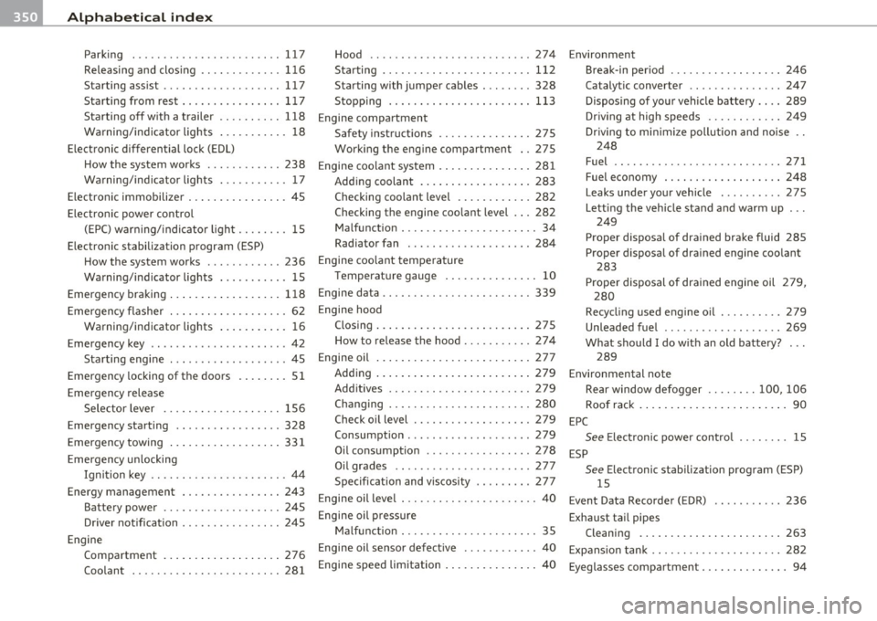
___ A_ l_. p_ h _ a_b_ e_ t_ic _a_ l_ in_ d_e _ x ____________________________________________ _
Parking ........ ..... .. .. .... ... 117 Hood .. .. .. .. .. .... ... . ... .. .. . 274
Releasing and clos ing .. .. ......... 116 Starting ........... .. .. .. ....... 112
Starting assist ................ ... 117 Sta rting with jumpe rr cab les ........ 328
Starting from rest . .. ...... ..... .. 117 Stopp ing ... .. ..... .... .. .. .. .. . 113
Sta rting off w ith a t railer ... . .. .. .. 118
Engine compartment
W arning/ind icator lights . .......... 18
Safety instruct ions .... .. .. .. .. ... 275
Elect ronic differential lock (EDL) Working the eng ine compartment . . 275
How the system works .... ... .. ... 238
Engine coo lant system . .. ... . ... .... . 281
Warning/ind icator lights . .......... 17
Adding coolant ... .... .. . .. ... .. . 283
Electronic immobilizer .. .. . ... ... .. ... 45
Checking coo la nt level . ..... ..... . 282
Electro nic powe r contro l Checking the engine coo
lant level . .. 282
( E PC) war ning/ indicato r light .. ...... 15 Ma
lfunction ... ................. .. 34
Electronic stabilization program (ESP) Radiator fan ...
...... .. .. .. .. ... 284
How the system works ............ 236 Engine coo
lant temperature
Wa rning/ind icator lights . .......... 15 T
emperat ure gauge . .... . ... .. .. . . 10
Emergency braking ..... .. .. .. .. .. ... 118 Engine data
... ... ...... ... .. .. .. .. . 339
Emergency flasher . . . . . . . . . . . . . . . . . . . 62
Engine hood
W arning/ind icator lights ... .. ... ... 16 Closing ........
...... ...... ..... 275
E mergency key .. ................ .... 42 How to re
lease the hood .......... . 2 7 4
Starting eng ine . .. .... .. ..... ..... 45 Engine oil
.... ..... ..... .... .. .. .. . 277
Emergency locking of the doors . ... .. .. 51 Adding ...
... .... .... .... ... . ... 279
Eme rgency release
Sele ctor leve r ............. .... .. 156 Add
itives ...... .. .. .. ...... .. ... 279
Changing ............ .... .. ..... 280
E mergency starting .. .. ... ....... ... 328
Emergency towing ..... .. .. ..... .... 331
Emergency u nlocking
Ignition key .. .... ............. ... 44
Energy management .......... .... .. 243
Battery power ................... 245
Dr iver not ification ..... .. .. ... .. .. 245 Check o
il level ............ .. .... . 279
Consumption ....... .. .. .. ....... 279
Oil consumption .... .... . ... .. .. . 278
Oi l grades .. ..... ............. .. 277
Specification and viscosity .. .. .. .. . 277
E ngine oil leve l ... .... ............. .. 40
E ngine oil pressure
M al fun ctio n ... ........... ...... .. 35
Engine
Compartment .. .. .. .. . ... ... .. .. 276
Coolant ...... .......... ...... .. 281 Engine oil sensor defec
tive ..... .. .. ... 40
Engine speed limitatiorn . ....... ..... .. 40 Environment
Break-in per iod ......... ... .. .. .. 246
Catalytic converte r ............... 24 7
Disposing of you r vehicl e battery .. .. 289
Dr iv ing at hig h speeds ............ 249
Dr iv ing to mi nimize poll ution and noise ..
248
Fuel .. .. .... ............. ...... 271
Fuel economy .. .... .... ... .. .. .. 248
Leaks under you r vehicle ... .. ... .. 275
Lett ing the vehicle stand and warm up ...
249
Proper disposa l of dra ined brake fluid 285
Proper disposal of d ra ined engine coo lant
283
Proper disposal of drained engine oil 279,
280
Recycl ing used e ng ine o il ... .. .. .. . 279
Unleaded fue l ............ ... .. .. 269
What should I do w it h an old batte ry?
289
E nvironmen tal note
Re ar w indow defogger ...... .. 100, 1 06
Roo f rack . . . . . . . . . . . . . . . . . . . . . . . . 90
EPC See Elect ronic power con tro l ........ 15
ESP See Electronic stabilization program (ESP)
15
Event Data Recorde r (EDR) 236
Exhaust tai l pipes
Cleaning ... .... ... .. . .... .... .. 263
E xp ans ion tank .. .. .. .. ............. 282
Eyeglasses compartment ......... . ... . 94