ECU AUDI A5 COUPE 2014 Owner's Guide
[x] Cancel search | Manufacturer: AUDI, Model Year: 2014, Model line: A5 COUPE, Model: AUDI A5 COUPE 2014Pages: 286, PDF Size: 70.99 MB
Page 208 of 286
206 Checking and filling
Checking and filling
Engine hood
Releasing and opening the engine hood
The engine hood is released from inside the
vehicle .
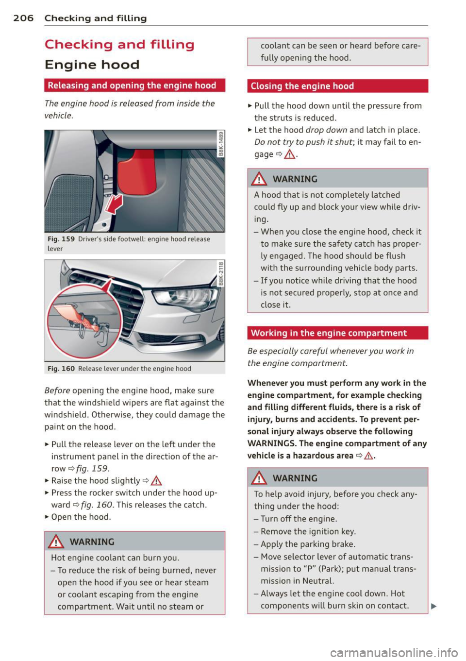
Fig . 159 D river' s side footwe ll: e ngin e hood re lease
lever
F ig. 160 Re lease lever u nde r the eng ine hood
Before openin g the engine hood, ma ke s ure
that the windshie ld w ipers are flat against the
windshield. Otherwise, they co uld damage the
pa int on the hoo d.
... Pull the release lever on the left unde r the
inst rument panel in the direction of the ar
row
c;, fig . 159.
... Raise the hood slightly r::;, .&,
... Press the rocke r swi tch u nder the hood up
ward
c;, fig . 160 . Th is re leases the catch .
... Ope n t he hood.
A WARNING
Hot engi ne co olan t ca n bur n you.
- T o redu ce the r is k o f being burned, never
op en t he ho od if yo u see or hea r steam
or cool an t esc aping from the en gine
c ompartment. Wait unti l no steam or co
olant can be seen or heard before care
fu lly opening the hood.
Closing the engine hood
... Pull the hood down until the pressure from
the struts is reduced .
... Le t the hood
drop down and latch in p lace.
Do not try to push it shut; it may fail to en
gage
r::;, .&, .
A WARNING
-
A ho od th at is not co mpletely latched
could fly u p an d block your view while driv
in g.
- Wh en you close the engi ne ho od, ch ec k it
t o make sure the sa fe ty ca tch has pro pe r
ly engaged . The hood s hould be flush
wit h the surroun ding vehicle body pa rts .
-If you notice while driv in g that t he hood
is not secured prope rly, sto p at once and
close it.
Working in the engine compartment
Be especially ca reful whenever you work in
the engine compartment.
Whenever you must perform any work in the
engine compartment, for example checking
and filling different fluid s, there is a ri sk of
injury , burns and accidents . To prevent per
sonal injury always observe the following
WARNINGS. The engine compartment of any
vehicle is a hazardous area
r::;, ,&. .
A WARNING
-To help avo id injury, before yo u check any-
thing unde r the hoo d:
- Turn off the eng ine.
- Remove the ignition key.
- Ap ply the park ing brake .
- Move selector leve r of automatic t rans -
miss io n to "P" (Par k); pu t man ual trans
miss ion in Neu tral.
- Al ways let the eng ine cool down. Hot
components wi ll burn skin on contact .
Page 232 of 286
230 Tire s and wheel s
the function of the tire pressure monitor
ing system*.
- Always inflate tires to the recommended
and correct tire pressure before driving
off.
- Driv ing with under inflated tires bend
more, letting them get too hot resu lting
in tread separation, sudden t ire fail ure
and loss of control.
- Excess ive speed and/overloading can
cause heat bui ld-up, sudden t ire failure
and loss of control.
- If the t ire pressure is too low or too high,
the tires w ill wear prematurely and the
vehicle will not hand le we ll.
- If the t i re is not flat and you do not have
to change a wheel immed iate ly, dr ive at
reduced speed to the nearest service sta
t ion to check the tire pressure a nd add
air as required.
0 Note
Dr iving without va lve stem caps can cause
damage to the t ire va lves . To prevent this,
always ma ke sure that facto ry installed
valve stem caps on all wheels a re secu re ly
mou nte d on the valve.
@) For the sake of the environment
Unde rinflated tires will a lso inc reas e the
fue l cons umption .
Tires and vehicle load limits
There are limits to the amo unt of load or
weight that any vehicle and any t ire can carry .
A vehicle that is overloaded w ill not handle
well and is more difficult to stop. Overloading
can not only lead to loss of vehicle contro l,
but c an also damage import ant parts of the
vehicle and can lead to sudde n tire failure, in
cluding a blowout and sudden deflation that
can cause t he veh icle to crash .
Your safety and that of your passengers a lso
depends on making sure that load limits are
not exceeded . Vehicle load includes everybody
and everyth ing in and on the vehicle. These load lim
its are technically referred to as the
vehicle's
Gro ss Vehicle Weight R ating
("GVWR").
T he "GVWR" includes t he weight of the basic
vehicle , a ll f actory installed accessories, a f ull
tank of fuel, oi l, coo lant and other f luids plus
maximum load. The max imum load incl udes
the number of passengers that the vehicle is
intended to carry ("seat ing capac ity ") wi th an
assumed we ight of 150 lbs . (68 kg) for each
passenger at a designated seating posit ion
and the total weight of a ny luggage in the ve
hicle. If you tow a trai le r, the we ight of the
t ra ile r hi tc h and the tongue we ight of the
l oaded tra iler mus t be include d as part of the
vehicle load .
T he
Gro ss Ax le Weight Rating ("GAWR ") is
the max imum load that can be applied a t each
of the veh icle's two axles .
T he Gross Vehicle Weight Rat ing and the
G ross Ax le Weig ht Ra ting are listed on the
sa fety comp lian ce s ticke r label loca ted on the
driver's side B-pillar. Yo ur Audi has 4 seat ing
pos itions , 2 in the front and 2 in the rea r fo r
total seati ng capacity of 4. Each seating posi
t ion has a seat belt c:>
page 129, Safety belts.
T he fact that there is an upper limit to yo ur
vehicle's Gross Vehicle Weight Rating means
t h at the total weight of whatever is being car
ried in the vehicle ( includ ing the weight of a
trailer hitch and the tongue weight of the
loaded tra iler) is lim ited. The more passen
gers in the vehicle or passengers who are
heavier tha n the sta ndard we igh ts assumed
mean that less we ight can be carried as lug
gage.
The tire pressure label o n your Aud i also lists
the max imum combi ned weig ht of all of the
occupants and luggage or other cargo that
t h e vehi cle can carry . Fo r th e lo ca tion of the
l a bel c:>page 226,
fig.168.
8_ WARNING
<=
Over loading a vehicle can cause loss o f ve -
hicl e co ntro l, a c rash or other accident, se-
rious personal injury, and even death. .,.
Page 241 of 286
driving a few yards and correct if neces
sary . Follow the instructions from the
snow cha in manufacturer when doing so.
(D Tips
Where snow chains are mandatory oncer
tain roads, this norma lly also applies to
veh icles with all wheel drive .
Wheel bolts
Wheel bolts must always be tightened to the
correct torque.
The design o f whee l bolts is matched to the
factory insta lled r ims . If different rims are fit
ted, the correct wheel bo lts wit h the right
l ength and correctly shaped bolt heads must
be used. This ensures that wheels are f itted
securely and that the brake system functions
correctly .
In certain circumstances, you may not use
wheel bo lts from a different vehicle -even if it
is the same model<=>
page 266.
A WARNING
Improperly tightened or maintained wheel
bolts can become loose caus ing loss of
cont ro l, a co llision and serious persona l in
Jury .
- Always keep the w heel bolts and the
threads in the wheel hubs clea n so the
w hee l bolts can t urn easily and be p rop
erly t igh tened.
- Never grease or oil the wheel bolts and
the threads in the wheel h ubs. They can
become loose wh ile d riving if greased or
oiled, even if tightened to the specified
torq ue.
- Only use whee l bo lts that belong to the
rim being installed .
- Never use different whee ls bolts on your
vehicle.
- Alw ays m ain ta in the co rrec t tig hten ing
torq ue fo r the wheel bo lts to reduce the
risk of a wheel loss . If the tightening tor
que of the wheel bo lts is too low, they
can loosen and come out when the vehi-
Tire s an d wheel s 239
cle is mov ing. If the tightening torq ue is
too high, the wheel bolts and threads
can be damaged and the whee l can be
come loose.
@ Note
The specified torque for the whee l bolts is
90 ft lbs . (120 Nm) w ith a tolerance of
± 7,4 ft lbs. (± 10 Nm). Torque whee l bolts
diagonally . After changi ng a wheel, the
torque m ust be checked as soon as poss i
ble with a to rque wrench -preferably by an
a uthorized Aud i dea le r or qualified wor k
shop .
Low aspect ratio tires
Your A udi is fac tory -eq uipped w ith low aspect
ratio tires . These tires have been tho ro ughly
tested and been se lected specifically for your
model for their superb performance, road fee l
and handling under a variety of driving condi
tions . Ask your authorized Aud i dealer for
more details .
The low aspect ratio of these t ires is ind icated
by a numeral of
55 or less in the tire's size
designation. The numera l represents the ratio
of the tire's sidewa ll height in relation to its
tread width exp ressed in percentage. Conven
tiona l tires have a he ight/w idth ratio of 60 or
more.
The performance of low-a spect-r atio tire s is
particularly sensit ive to improper inflation
pre ssure. It is therefor e important that low
a spect ratio tire s are inflated to the specified
pres sure and that th e inflation pr essure i s
regularly checked and maintained. Tire pre s
sure s should be chec ked at lea st once a
month and always before a long trip
<=> page 228 , Checking tire pressure.
What you can do to avo id tire and rim
damage
Low aspect ratio tires can be damaged mo re
easily by impact w ith potholes, curbs, gull ies
or ridges on the road, particularly if the tire is
under inflated . ..,.
•
•
Page 245 of 286
What do I do now?
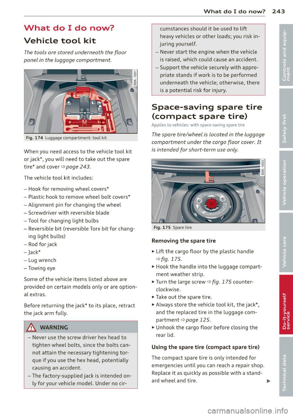
Vehicle tool kit
The tools ore stored underneath the floor
panel in the luggage comportment.
Fig. 174 Luggage compartment: tool kit
When you need access to the veh icle tool kit
or jack*, you will need to take o ut the spare
tire* and cover¢
page 243.
The vehicle tool kit includes:
- Hook for removing wheel covers*
- Plastic hook to remove wheel bolt covers*
- Alignmen t pin for ch anging the whee l
- Screwdriver w ith reversible blade
- Too l for chang ing light bulbs
- Reversible bit (reversible Torx bit for chang -
ing light bulbs)
- Rod for jack
- Jack*
- Lug wrench
- Towing eye
Some of the vehi cle items listed above are
p rov ided o n certain models o nly or are opt io n
al extras .
Before returning the jack* to its place, retract
the jack arm fully.
.&, WARNING
-
-Never use the screw d river hex head to
tighten whee l bolts, since the bolts can
not attain the necessary tightening tor
que if yo u use the hex head, potentially
caus ing an accident.
- The factory-supplied jac k is intended on
ly for your vehicle model. Unde r no cir-
What do I d o now ? 243
cumstances should it be used to lift
heavy veh icles or other loads; you risk in
juring yourself.
- Never start the engine when the vehicle
is raised, wh ich could cause an acc ident.
- Support the vehicle securely w it h appro
priate stands if work is to be performed
underneath the vehicle; otherwise , there
is a pote ntia l risk for injury .
Space-saving spare tire
(compact spare tire)
App lies to vehicles: wit h space -saving spare t ire
The spore tire/wheel is located in the luggage
comportment under the cargo floor cover. It
is intended for short-term use only .
Fig. 175 Spa re tir e
Remo ving th e spare tire
.. Lift the cargo floor by the p lastic handle
¢ fig. 175 .
.. Hook the handle into the luggage compart
ment wea ther strip .
.,. Turn the large screw <=>
fig. 175 counter
clockw ise.
.,. Take out the spa re tire .
.,. Always s tore the vehicle tool kit, the jack*,
and the rep laced tire in the luggage com
partment
¢ page 125 .
.. Unhook the cargo floor before closing the
rear lid .
Using th e spare tire (compact spar e tire )
The compact spare t ire is only intended fo r
eme rgencies unt il you can reach a repa ir sh op.
Rep lace it as qu ickly as possible with a stand -
ard whee l and tire.
Ill-
Page 249 of 286
@ Tips
-Never use the hexagonal socket in the
handle of the screwdriver to loosen or
tighten the wheel bolts.
- If a whee l bolt is very tight, you may find
it easier to loosen by carefully pushing
down on the end of the wheel bolt
wrench w ith
one foot only. As you do so,
hold on to the car to keep your ba lance
and take ca re not to slip.
Raising the vehicle
The vehicle must be li~ed with the jack first
before the wheel can be removed .
*- '*
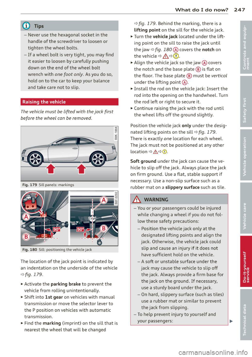
Fig. 1 79 Sill pane ls: ma rk ings
Fi g. 180 Sill: posit ion ing the ve hicle
jack
The location of the jack point is indica ted by
a n in den ta ti on on the underside of the vehicle
¢ fig . 179.
"'Activate the parking b rake to prevent the
vehicle from ro lling u ninten tionally.
"' Shift in to
1st gear on vehicles with manua l
transmission or move the se lector lever to
the P position on vehicles with automatic
transmission.
"' Find the
marking (imprint) on the sill that is
nearest the wheel that w ill be changed
What do I d o now ? 24 7
¢ fig. 179. Behind the marking, there is a
lifting point on the sill for the vehicle jack.
"' Turn the
vehicle ja ck located under the lift
ing point on the sill to ra ise the jack until
the jaw ¢
fig. 180 @ covers the notch on
the vehicle
¢ & ¢ (D .
"'Align the vehicle jack so the jaw@ covers
th e notch and the base plate @ is flat on
the floor. The base plate @ must be
vertical
unde r th e lift ing po in t @ .
"'I nsta ll the rod on the vehicle jack : Inser t the
rod into the opening on the handwheel. T urn
the rod left or right to secure it.
"' Continue raising the jack w ith the rod unt il
the wheel lifts off the ground slightly.
Position the veh icle jack
only under the desig
nated lifting points on the sill ¢
fig. 179 .
There is exactly one locat ion for each wheel.
The jack must not be positioned at any other location c> &, c>(D.
Soft ground under the jack can cause the ve
hicle to slip off the jack. Always place the jack
on f irm ground. Use a f lat, stab le support if
necessary . Use a non-slip surface such as a
rubber mat on a
s lipp ery surface such as tile .
A WARNING
-You or your passengers co uld be in ju red
while changing a wheel if you do no t fo l
low these safety p re ca utions:
- Position t he veh icle jack on ly at the
designated lifting poi nts and align the
jack. Otherw ise, the vehicle jack could
slip a nd cause an injury if it does not
have sufficie nt hold o n the vehicle.
- A soft or unstable surface under the
jac k may cause the ve hicle to slip off
the jack . A lways prov ide a fi rm base for
the jack o n the ground. If necessa ry,
u se a st ur dy boa rd under the jack .
- On hard, sl ippery su rface (such as t iles)
u se a rubber mat or simi lar to prevent
the j ack from slipping.
- T o help preve nt injury to yo urself and
your pas sengers:
Page 250 of 286
248 What do I do now?
-Do not raise the vehicle unti l you are
sure the jack is securely engaged.
- Passengers must not remain in the ve
hicle when it is jacked up.
- Make sure that passengers wait in a
safe p lace away from the vehicle and
well away from the road and traffic.
- Make sure jack position is correct, ad
just as necessary and then continue to ra ise the jack.
CD Note
Do not lift the vehicle by the sill. Position
the vehicle jack only at the designated lift
ing points on the sill. Otherwise, your vehi
cle will be damaged.
Taking the wheel off/installing the spare
tire
Follow these instructions step-by-step for
changing the wheel .
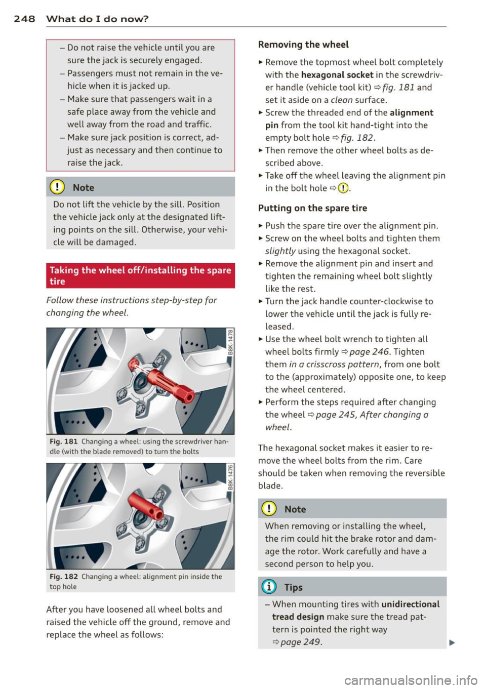
Fig. 181 Changing a w hee l: usi ng the screwdriver han ·
dle (with the blade r~mo ved) to turn th e bo lts
Fig. 182 C hangin g a w hee l: alig nmen t pin inside the
to p hole
After you have loosened a ll wheel bolts and
ra ised the veh icle off the ground, remove and
replace the wheel as follows:
Removing the wheel
"' Remove the topmost wheel bolt comp letely
with the
hexagonal socket in the screwdriv
er handle (vehicle tool kit)¢
fig. 181 and
set it aside on a
clean surface.
"' Screw the threaded end of the
alignment
pin
from the tool kit hand-tight into the
empty bolt hole¢
fig. 182.
"' Then remove the other wheel bolts as de
scribed above.
"' Take off the whee l leaving the alignment pin
in the bolt hole ¢(D .
Putting on the spare tire
"' Push the spare tire over the alignment p in.
"' Screw on the wheel bolts and tighten them
slightly using the hexagonal socket .
"' Remove the alignment pin and insert and
tighten the remain ing wheel bolt slightly
like the rest.
"' Turn the jack handle counter-clockwise to
lower the veh icle until the jack is fully re
leased.
"' Use the wheel bo lt wrench to tighten all
wheel bolts firmly¢
page 246 . Tighten
them
in a crisscross pattern, from one bolt
to the (approximately) opposite one, to keep
the wheel centered.
"' Perform the steps required after changing
the wheel
c::> page 245, After changing a
wheel.
T he hexagonal socket ma kes it easier to re
move the wheel bolts from the rim. Care
sho uld be taken when removing the reversible
blade .
CD Note
When removing or installing the wheel,
the rim could hit the brake rotor and dam
age the rotor. Work carefu lly and have a
second person to help you.
(D Tips
-When mount ing tires with unidirectional
tread design
make sure the tread pat
tern is po inted the right way
c::> page 249. Iii>
Page 251 of 286

-The wheel bol ts should be clean and easy
to tu rn. Check for d irt and corrosion on
t h e mat ing s urfaces of both the whee l
and t he hu b. Remove a ll dirt from these
su rfaces before remo unt ing t he wheel.
- Do n ot use the hexagonal socket in the
screwdriver ha ndle to loosen or tig hten
t h e wheel bo lts .
Tires with unidirectional tread design
Tires with unidirectional tread design must be
mounted with their tread pattern pointed in the right direction.
Using a spare tire with a tread pattern
intended for use in a specific direction
When using a spare tire w ith a t read patte rn
i ntended for use in a specific direction, please
n ot e th e follow ing:
- The direction of rotation is ma rked by an
ar
row on the s ide of the t ire .
-If the spare t i re has to be installed in the in
correct di rection, use the spare tire only
temporar ily since the t ire will not be able to
achieve its optimum perfo rma nce character
ist ics with r ega rd to aquaplani ng, noise and
wea r.
- We recommend that you pay particular at
tent io n t o this fact du ring wet weathe r and
t h at you adjus t your spee d to matc h road
cond itio ns.
- Replace th e flat tire w ith a n ew one and
have it ins talled o n your ve hicle as soon as
poss ible to re st ore the hand ling advant ages
of a uni direct io na l t ire .
Notes on wheel changing
Please rea d the information ¢ page 233, New
tires and replacing tires and wheels
if you are
going to use a spare t ire which is different
from the tires on your ve hicle.
Afte r you change a tire :
-Check the tire pressure on the spare imme
diately after installation . What do I do now? 249
- Have the wheel bolt tightening torque
checked with a torque wrench as soon a s
possible by your authorized Audi dealer or
qualified workshop.
- With steel and alloy wheel rims , the wheel
bolts are cor rectly tightened at a torque of
90 ft lbs. (120 Nm ).
- If you notice that the wheel bolts are cor·
roded and difficult to turn while changing
a tire, they should be replaced before you
check the tightening torque .
- Replace the flat tire with a new one and
have it installed on your veh icle as soon as
possible. Remount the wheel cover.
Until then , drive with extra care and at re·
duced speeds.
A WARNING
-
- If you are going to equ ip your ve hicle
w it h tires o r rims which differ from those
which w ere fac to ry installed, t hen be
s ure to re ad the information ¢
page 233,
N ew tire s and re pla cing tires and
whee ls.
- Always make s ure th e da maged wheel o r
eve n a flat t ire and t he j ack and to ol ki t
a re p roperly secu red in the lugg age com
pa rtment an d are no t loose in the pas
sen ger compartment.
- In an accident or sud den maneuver they
co uld f ly forwa rd, in ju ring a nyo ne in the
ve hicle .
-A lways s to re damage d wheel, jack and
too ls sec urely in the luggage compa rt
ment . Othe rwise, in a n accident o r su d
den maneuver they co uld f ly forwa rd,
causing inju ry to passengers in the ve hi·
cle.
~ Note
Do not use comme rcially ava ilab le tire
sea lants. Ot herwise, t he e lectr ica l comp o
n ents of t he tire pressu re monitoring sys
t em * w ill no longe r work pr operly and the
senso r fo r th e tire pressure moni tor ing
syst em* will have to be replac ed by quali
fied wor ksh op. •
•
Page 259 of 286
-Jumper cables must be long enough so
that the vehicles do not t ouch.
- W hen connecting jumper ca bles, make
sure that they cannot get caught in any
moving parts in the eng ine compart
ment.
- Do not bend over the batteries - danger
of chemical burns!
- The battery ce ll locking screws must be
t ightened securely .
- Before you check anything in the engine
compartment, always read and heed all
WARNINGS ¢
page 206.
Improper hook-up of jumper cables can ru
in the generator.
- Always connect POSITIVE( +) to POSI
TIVE(+), and NEGATIVE( -) to NEGATIVE
( - ) ground post of the battery manager
control unit.
- Check that all screw plugs on the battery
ce lls are screwed in firmly . If not, tighten
plugs p rior to connecting clamp on nega
tive battery terminal.
- Please note that the procedure for con
necting a jumper cable as described
above applies spec ifically to the case of
your vehicle be ing jump started. When
you are givi ng a jump start to another ve
hicle, do
not connect the negat ive( -) ca
ble to the negat ive( -) term inal on the
discharged battery @¢
fig. 188. In
stead, securely connect the negative(- )
cable to e ither a solid metal component
that is firmly bolted to the engine block
or to the engine block itse lf. If the bat
tery that is being charged does not vent
to the outside, escaping battery gas
could ignite and explode!
Em erg en cy si tuation s 257
Emergency towing
with commercial tow
truck
General hints
Your Audi requires special handling for tow
ing.
T he following information is to be used by
commercial tow t ruck operators who know
how to operate their equipment safely.
- Never tow your Audi , towing will cause
damage to the engine a nd transmi ssion.
- Never wrap th e safet y chain s or winch c a
ble s around th e brak e lin es.
- To prevent unne ce ss ary dam age, your Aud i
mu st be t ransp orted with a flat bed truck .
- To load th e vehi cle on to the fl at bed , use
the t owing loop found in the vehicle t ool s
and atta ch to the front or rear anch o rage
r=:> page 258 and ¢page 258 .
A WARNING
A vehicle being towed is not safe for pas
sengers. Never allow anyone to ride in a
vehicle being towed, for any reason.
-
•
•
Page 261 of 286
Loading the vehicle onto a flat bed truck
Fig. 193 Ve hicle on fla t bed tr uck
Front hook up
.. Align the vehicle with the centerline of the
car carr ier ramp.
.. Attach the winch hook to the front towline
eye previously installed .
Rear hook up
.. Align the vehicle w ith the centerline of the
car carrier ramp.
.. Attach the winch hook to the rear towline
eye previously installed.
(D} Tips
Check carefully to make sure the hook- up
is secure before moving the car up the flat
bed truck ramp .
Lifting vehicle
Lifting with workshop hoist and with
floor jack
The vehicle may only be li~ed at the lifting
points illustrated .
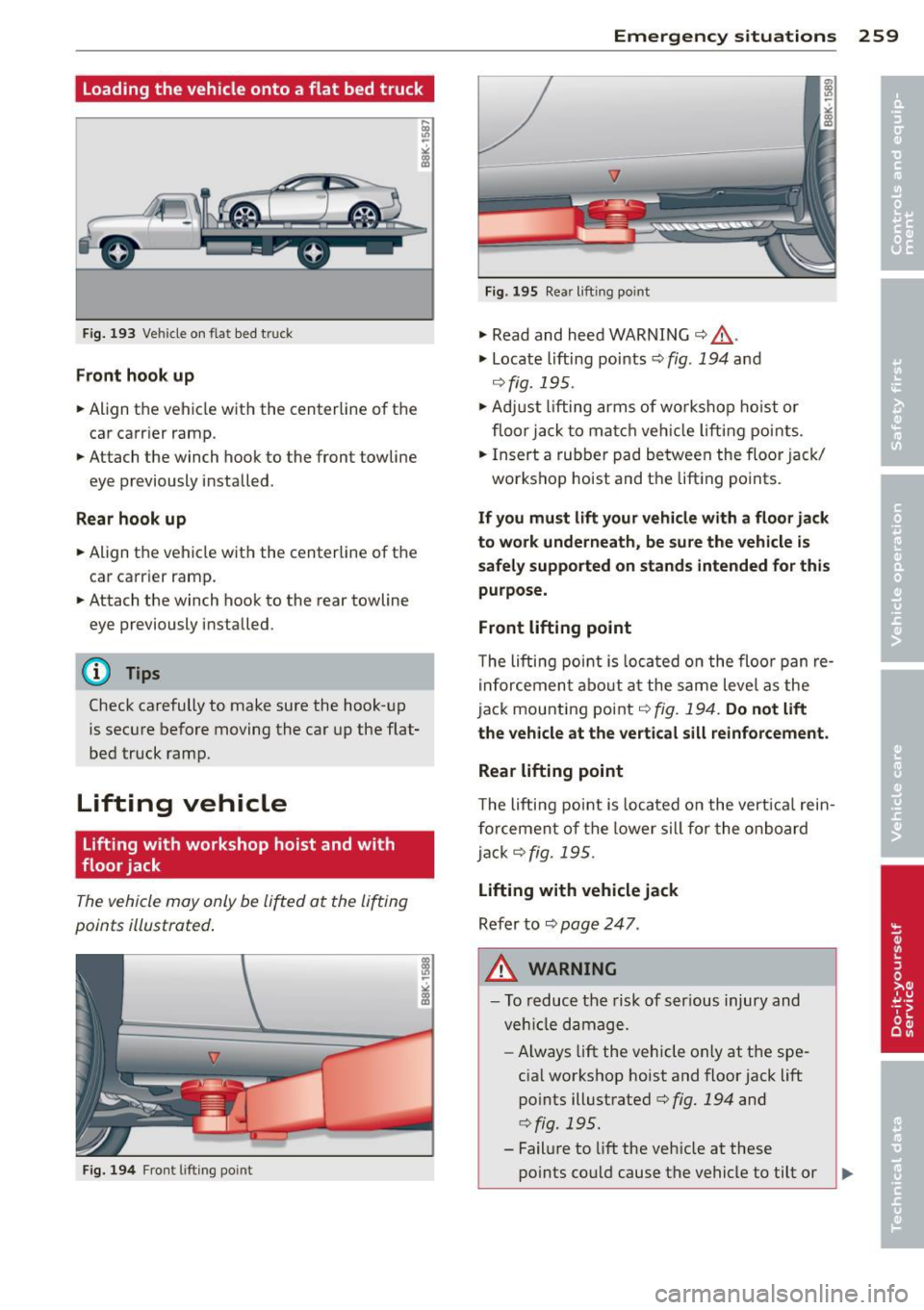
Fig. 194 Fro nt l ift ing po int
Emergenc y situ ation s 259
Fig. 1 9 5 Rea r liftin g po int
.,. Read and heed WARNING c::> .&, .
.,. Locate lifting points c::> fig. 194 and
¢ fig. 195 .
.,. Adju st lifting arms of wo rkshop ho ist o r
floor jack to ma tch veh icle lifting points.
.. Insert a rubbe r pad be tween the floor jack/
workshop hoist and the lift ing points.
If y ou mu st lift your veh icl e with a fl oor jack
to w ork und erneath , be sure the vehicle is
safel y supported on stand s intended for thi s
purpo se .
Front lifting point
T he lifti ng point is loca ted o n the floo r pan re
i nforcemen t abo ut a t the same level as the
jack mounting point
c::> fig. 194. Do not lift
the vehicle at the vertic al sill reinforcement.
Rear lifting point
T he lifting point is located o n the vert ica l rein
f o rcement of the lower s ill for the on board
jack
c::> fig. 195 .
Lifting with vehicle jack
Refer to c:;, page 247 .
A WARNING
-To reduce the risk of ser ious injury and
veh icle damage.
- Always lift the vehicle only at the spe
cia l workshop hoist and floor jack lift
points illustrated
c:;, fig. 194 and
c:;, fig. 195.
- Fail ure to lift the veh icle at these
-
po ints could cause the vehicle to tilt or ..,.
Page 267 of 286
complexity of today's automobi les, have
steadi ly reduced the scope of maintenance
and repairs which can be carried out by vehicle
owners.
Also, safe ty and e nvir onm en tal con
cerns place very strict limits on the nature of
repairs and adjustments to engine and trans
miss io n pa rts which an owner can perform .
Maintenance, adjustments and repairs usua lly
require special tools, testing devices and oth
er equipment avai lab le to specially trained
workshop personnel in order to assure prope r
performance, reliab ility and safety of the vehi
cle and its many systems .
Improper ma intenance, adjustments and re
pa irs can impair the operation and reliability
of your vehicle and even void your vehicle war ranty. The refo re, p roof of servic ing in accord
ance w ith the maintenance sched ule may be a
condition for upholding a poss ible war ranty
claim made within the warranty period.
Above all, operational safety can be adversely
affected, crea ting unnecessary risks for you
and your passengers.
If in doubt about any servicing, have it done
by your authorized Audi dealer or any properly
equ ipped and qua lified workshop. We st rong
l y urge you to g ive your authorized Audi dea ler
the opportunity to perform all scheduled
maintenance and necessary repairs . Your dea l
er has the facilities, original parts and trained
specialists to keep your veh icle running prop
erly.
Performing limit ed m aintenance you rself
The following pages describe a limited num
ber of procedures which can be performed on
your vehicle with ordinary too ls, should the
need arise and trained personnel be unavaila
ble. Before performing any of these proce
dures, always thoroughly read all of the appli
cable text and carefully follow the instruc
tions given. Always rigorously obse rve the
WARNINGS provided.
B efore you check anything in th e engine
compartment, a lways re ad and heed all
Con sumer In formation 265
WARNINGS ¢ & and ¢ & in Working in the
engine comportment on page 206 .
A WARNING
-Ser ious personal injury may occur as a re
sult of improperly performed mainte
nance, adjustments or repa irs.
-Always be extremely careful when work
ing on the vehicle. Always follow com
mon ly accepted safety practices and gen
eral common sense. Never r isk personal
lnJUry.
- Do not attempt any of the ma intenance,
checks or repairs descr ibed on the fol
lowing pages if you are not fully fam iliar
wit h these or othe r pro cedures with re
spect to t he veh icle, or are uncerta in how
to p roceed .
- Do not do any work without the proper
too ls and equipment. Have the necessary
work done by your authorized A udi deal
er or any properly equipped and qualified
wo rkshop.
- The engine compartment o f any motor
veh icle is a potentially hazardous area.
Never reach into the area around or
touch the radiator fan. It is temperature
contro lled and can switch on suddenly -
even when the engine is off and the igni
tion key has been removed. The rad iator
fan switches on automat ica lly when the
coo lant reaches a certai n temperatu re
and will cont inue to run until the coo lan t
tempera ture drops .
- Always remove the ign itio n key befo re
anyone gets under the vehicle.
- Always support your veh icle with safety
s tands i f it is necessary to work under
neath the vehicle. The jack s upplied with
the vehicle is not adequate for this pur
pose and cou ld collapse causing serio us
personal injury.
- If you must work underneath the vehicle
with the wheels on the ground, a lways
make sure the vehicle is on leve l ground,
that the wheels are a lways securely
blocked a nd that the engine cannot be
started.
•
•