heater AUDI A6 1995 C5 / 2.G ATQ Engine Motronic Injection System Servicing Workshop Manual
[x] Cancel search | Manufacturer: AUDI, Model Year: 1995, Model line: A6, Model: AUDI A6 1995 C5 / 2.GPages: 78, PDF Size: 1 MB
Page 7 of 78
24-5
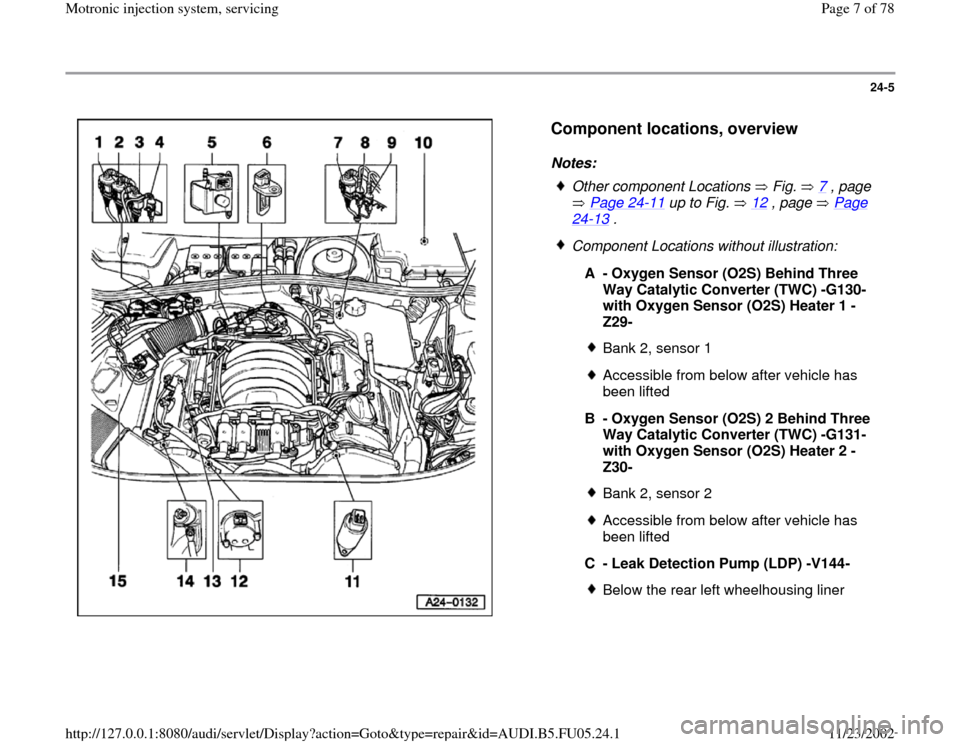
Component locations, overview
Notes:
Other component Locations Fig. 7
, page
Page 24
-11
up to Fig. 12
, page Page
24
-13
.
Component Locations without illustration:
A - Oxygen Sensor (O2S) Behind Three
Way Catalytic Converter (TWC) -G130-
with Oxygen Sensor (O2S) Heater 1 -
Z29-
Bank 2, sensor 1Accessible from below after vehicle has
been lifted
B - Oxygen Sensor (O2S) 2 Behind Three
Way Catalytic Converter (TWC) -G131-
with Oxygen Sensor (O2S) Heater 2 -
Z30- Bank 2, sensor 2Accessible from below after vehicle has
been lifted
C - Leak Detection Pump (LDP) -V144-Below the rear left wheelhousing liner
Pa
ge 7 of 78 Motronic in
jection s
ystem, servicin
g
11/23/2002 htt
p://127.0.0.1:8080/audi/servlet/Dis
play?action=Goto&t
yp
e=re
pair&id=AUDI.B5.FU05.24.1
Page 8 of 78
24-6
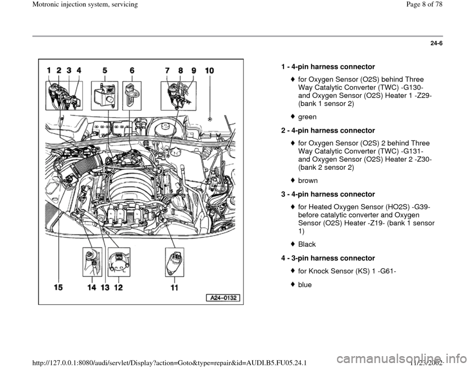
1 -
4-pin harness connector
for Oxygen Sensor (O2S) behind Three
Way Catalytic Converter (TWC) -G130-
and Oxygen Sensor (O2S) Heater 1 -Z29-
(bank 1 sensor 2) green
2 -
4-pin harness connector for Oxygen Sensor (O2S) 2 behind Three
Way Catalytic Converter (TWC) -G131-
and Oxygen Sensor (O2S) Heater 2 -Z30-
(bank 2 sensor 2) brown
3 -
4-pin harness connector for Heated Oxygen Sensor (HO2S) -G39-
before catalytic converter and Oxygen
Sensor (O2S) Heater -Z19- (bank 1 sensor
1) Black
4 -
3-pin harness connector for Knock Sensor (KS) 1 -G61-blue
Pa
ge 8 of 78 Motronic in
jection s
ystem, servicin
g
11/23/2002 htt
p://127.0.0.1:8080/audi/servlet/Dis
play?action=Goto&t
yp
e=re
pair&id=AUDI.B5.FU05.24.1
Page 9 of 78
24-7
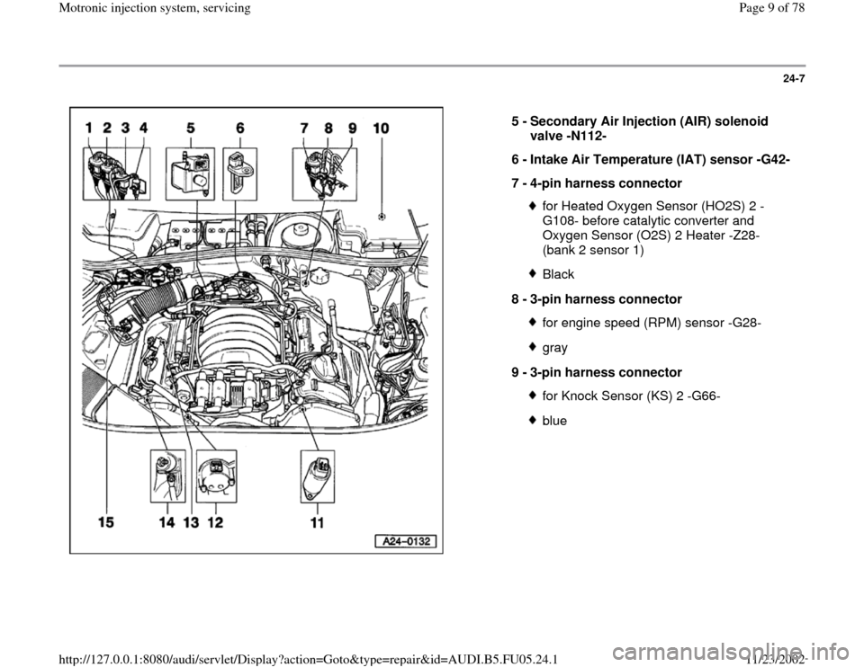
5 -
Secondary Air Injection (AIR) solenoid
valve -N112-
6 -
Intake Air Temperature (IAT) sensor -G42-
7 -
4-pin harness connector
for Heated Oxygen Sensor (HO2S) 2 -
G108- before catalytic converter and
Oxygen Sensor (O2S) 2 Heater -Z28-
(bank 2 sensor 1) Black
8 -
3-pin harness connector for engine speed (RPM) sensor -G28-gray
9 -
3-pin harness connector for Knock Sensor (KS) 2 -G66-blue
Pa
ge 9 of 78 Motronic in
jection s
ystem, servicin
g
11/23/2002 htt
p://127.0.0.1:8080/audi/servlet/Dis
play?action=Goto&t
yp
e=re
pair&id=AUDI.B5.FU05.24.1
Page 10 of 78
24-8
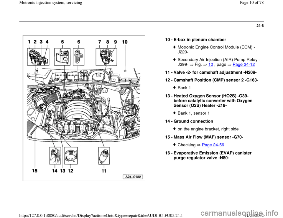
10 -
E-box in plenum chamber
Motronic Engine Control Module (ECM) -
J220- Secondary Air Injection (AIR) Pump Relay -
J299- Fig. 10
, page Page 24
-12
11 -
Valve -2- for camshaft adjustment -N208-
12 -
Camshaft Position (CMP) sensor 2 -G163-
Bank 1
13 -
Heated Oxygen Sensor (HO2S) -G39-
before catalytic converter with Oxygen
Sensor (O2S) Heater -Z19- Bank 1, sensor 1
14 -
Ground connection on the engine bracket, right side
15 -
Mass Air Flow (MAF) sensor -G70- Checking Page 24
-56
16 -
Evaporative Emission (EVAP) canister
purge regulator valve -N80-
Pa
ge 10 of 78 Motronic in
jection s
ystem, servicin
g
11/23/2002 htt
p://127.0.0.1:8080/audi/servlet/Dis
play?action=Goto&t
yp
e=re
pair&id=AUDI.B5.FU05.24.1
Page 12 of 78
24-10
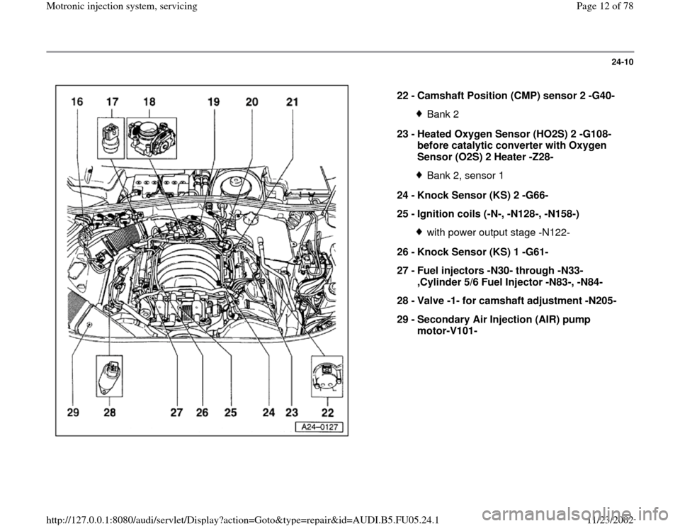
22 -
Camshaft Position (CMP) sensor 2 -G40-
Bank 2
23 -
Heated Oxygen Sensor (HO2S) 2 -G108-
before catalytic converter with Oxygen
Sensor (O2S) 2 Heater -Z28- Bank 2, sensor 1
24 -
Knock Sensor (KS) 2 -G66-
25 -
Ignition coils (-N-, -N128-, -N158-) with power output stage -N122-
26 -
Knock Sensor (KS) 1 -G61-
27 -
Fuel injectors -N30- through -N33-
,Cylinder 5/6 Fuel Injector -N83-, -N84-
28 -
Valve -1- for camshaft adjustment -N205-
29 -
Secondary Air Injection (AIR) pump
motor-V101-
Pa
ge 12 of 78 Motronic in
jection s
ystem, servicin
g
11/23/2002 htt
p://127.0.0.1:8080/audi/servlet/Dis
play?action=Goto&t
yp
e=re
pair&id=AUDI.B5.FU05.24.1
Page 21 of 78
24-19
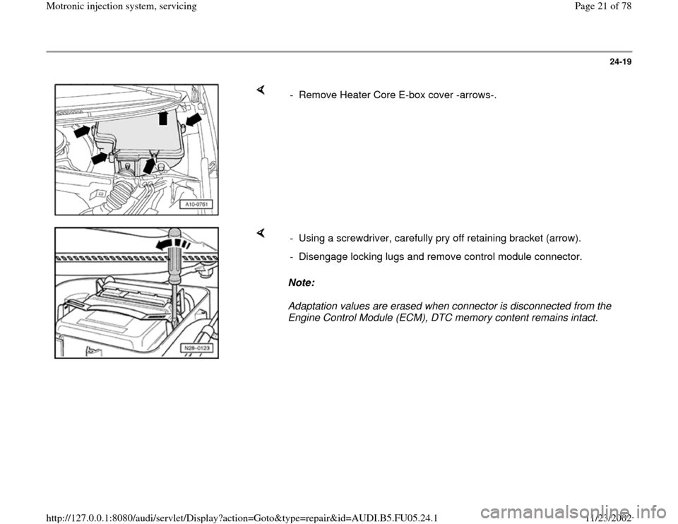
- Remove Heater Core E-box cover -arrows-.
Note:
Adaptation values are erased when connector is disconnected from the
Engine Control Module (ECM), DTC memory content remains intact. - Using a screwdriver, carefully pry off retaining bracket (arrow).
- Disengage locking lugs and remove control module connector.
Pa
ge 21 of 78 Motronic in
jection s
ystem, servicin
g
11/23/2002 htt
p://127.0.0.1:8080/audi/servlet/Dis
play?action=Goto&t
yp
e=re
pair&id=AUDI.B5.FU05.24.1
Page 24 of 78
24-22
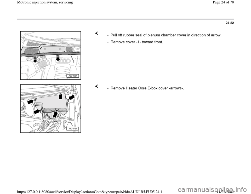
- Pull off rubber seal of plenum chamber cover in direction of arrow.
- Remove cover -1- toward front.
- Remove Heater Core E-box cover -arrows-.
Pa
ge 24 of 78 Motronic in
jection s
ystem, servicin
g
11/23/2002 htt
p://127.0.0.1:8080/audi/servlet/Dis
play?action=Goto&t
yp
e=re
pair&id=AUDI.B5.FU05.24.1