wiring AUDI A6 1995 C5 / 2.G ATQ Engine Oxygen Sensor Control Checking
[x] Cancel search | Manufacturer: AUDI, Model Year: 1995, Model line: A6, Model: AUDI A6 1995 C5 / 2.GPages: 63, PDF Size: 0.31 MB
Page 2 of 63
24-77
If voltage change does not occur or occurs only
slowly, the following malfunctions could be
present:
Slits or holes in sensor head clogged.
Sensors suffered thermal overload.
Transition resistance in signal wire or Ground
(GND) wire.
Sensor too cold, sensor heating not
functioning.
Sensor damaged by contact spray or similar
substance (contact spray is drawn through the
fine hollow interiors by thermal fluctuations and
capillary action into the electrical wiring in
sensor).
Sensor damaged by silicon vapors (the use of
sealants containing silicon leads to trace
elements of silicon being taken in by the
engine. These silicon elements are not
combusted and damage the oxygen sensor).
Pa
ge 2 of 63 Ox
yg
en sensor control, checkin
g
11/23/2002 htt
p://127.0.0.1:8080/audi/servlet/Dis
play?action=Goto&t
yp
e=re
pair&id=AUDI.B5.FU05.24.3
Page 17 of 63
24-90
Check oxygen sensor wires bank 1 for Heated
Oxygen Sensor (HO2S) 2 -G39-.
Component location of harness connectors
Overview of component locations, page Page
24
-5
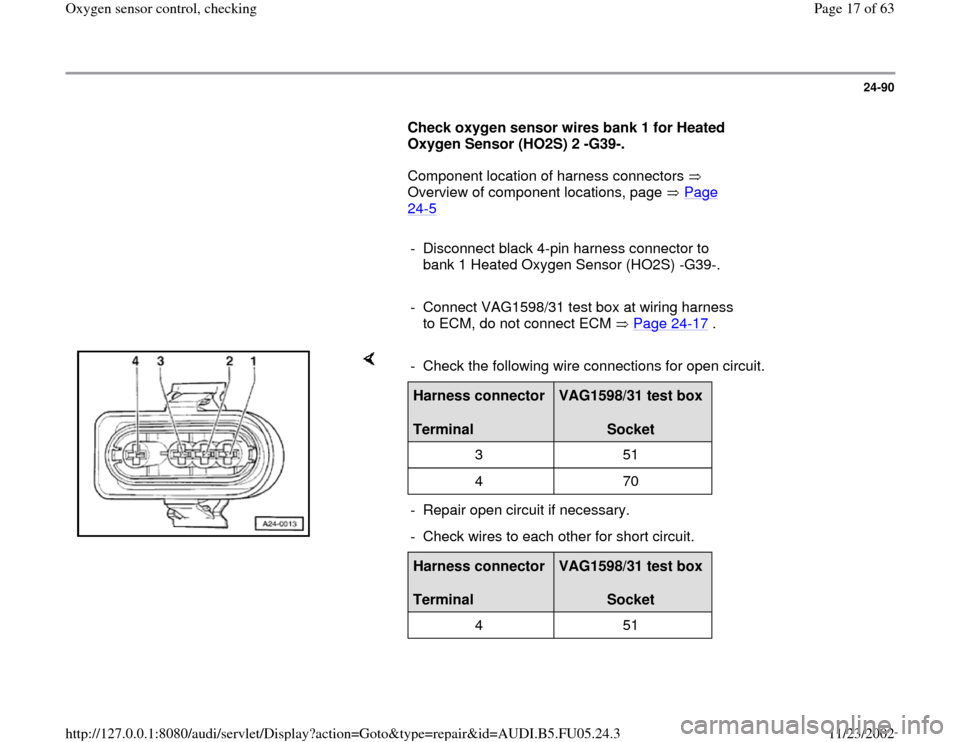
- Disconnect black 4-pin harness connector to
bank 1 Heated Oxygen Sensor (HO2S) -G39-.
- Connect VAG1598/31 test box at wiring harness
to ECM, do not connect ECM Page 24
-17
.
- Check the following wire connections for open circuit.Harness connector
Terminal
VAG1598/31 test box
Socket
3 51
4 70
- Repair open circuit if necessary.
- Check wires to each other for short circuit.Harness connector
Terminal
VAG1598/31 test box
Socket
4 51
Pa
ge 17 of 63 Ox
yg
en sensor control, checkin
g
11/23/2002 htt
p://127.0.0.1:8080/audi/servlet/Dis
play?action=Goto&t
yp
e=re
pair&id=AUDI.B5.FU05.24.3
Page 18 of 63
24-91
If no malfunctions are found in wires:
Check oxygen sensor wires bank 2 for Heated Oxygen Sensor
(HO2S) 2 -G108-.
Component location of harness connectors Overview of component
locations, page Page 24
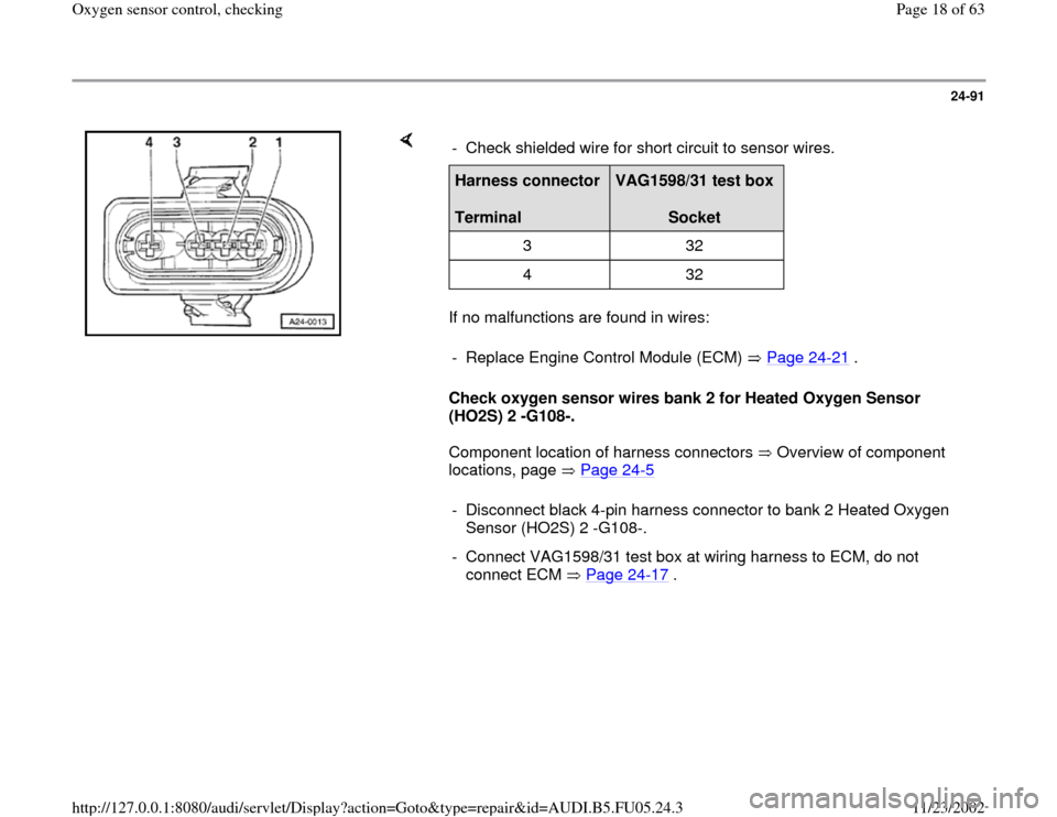
-5 - Check shielded wire for short circuit to sensor wires.
Harness connector
Terminal
VAG1598/31 test box
Socket
3 32
4 32
- Replace Engine Control Module (ECM) Page 24
-21
.
- Disconnect black 4-pin harness connector to bank 2 Heated Oxygen
Sensor (HO2S) 2 -G108-.
- Connect VAG1598/31 test box at wiring harness to ECM, do not
connect ECM Page 24
-17
.
Pa
ge 18 of 63 Ox
yg
en sensor control, checkin
g
11/23/2002 htt
p://127.0.0.1:8080/audi/servlet/Dis
play?action=Goto&t
yp
e=re
pair&id=AUDI.B5.FU05.24.3
Page 41 of 63
24-109
Evaluation of display group 037 and 038 Display field: 2
Possible cause
Corrective action
constant
about 0.450 V
Open circuit in wire 4 between oxygen sensor
and control module - Check primary voltage Page 24
-111
Open circuit in wire 3 between oxygen sensor
and control module
larger than
1.000 V Short circuit to B+ in wire 4 between oxygen
sensor and control module - Check oxygen sensor wiring and oxygen sensor
behind catalytic converter Page 24
-112
smaller than
0.150 V
Short circuit to Ground (GND) in wire 4 between
oxygen sensor and control module
Pa
ge 41 of 63 Ox
yg
en sensor control, checkin
g
11/23/2002 htt
p://127.0.0.1:8080/audi/servlet/Dis
play?action=Goto&t
yp
e=re
pair&id=AUDI.B5.FU05.24.3
Page 44 of 63
24-112
Testing Oxygen Sensor Wires
Component location of harness connectors
Overview of component locations, page Page
24
-5
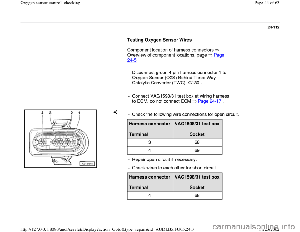
- Disconnect green 4-pin harness connector 1 to
Oxygen Sensor (O2S) Behind Three Way
Catalytic Converter (TWC) -G130-.
- Connect VAG1598/31 test box at wiring harness
to ECM, do not connect ECM Page 24
-17
.
- Check the following wire connections for open circuit.Harness connector
Terminal
VAG1598/31 test box
Socket
3 68
4 69
- Repair open circuit if necessary.
- Check wires to each other for short circuit.Harness connector
Terminal
VAG1598/31 test box
Socket
4 68
Pa
ge 44 of 63 Ox
yg
en sensor control, checkin
g
11/23/2002 htt
p://127.0.0.1:8080/audi/servlet/Dis
play?action=Goto&t
yp
e=re
pair&id=AUDI.B5.FU05.24.3
Page 46 of 63
24-114
Check oxygen sensor wires for Oxygen
Sensor (O2S) 2 Behind Three Way Catalytic
Converter (TWC) -G131-.
Component location of harness connectors
Overview of component locations, page Page
24
-5
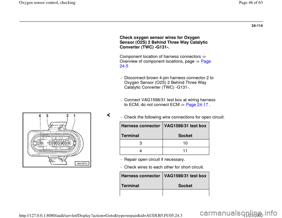
- Disconnect brown 4-pin harness connector 2 to
Oxygen Sensor (O2S) 2 Behind Three Way
Catalytic Converter (TWC) -G131-.
- Connect VAG1598/31 test box at wiring harness
to ECM, do not connect ECM Page 24
-17
.
- Check the following wire connections for open circuit.Harness connector
Terminal
VAG1598/31 test box
Socket
3 10
4 11
- Repair open circuit if necessary.
- Check wires to each other for short circuit.Harness connector
Terminal
VAG1598/31 test box
Socket
Pa
ge 46 of 63 Ox
yg
en sensor control, checkin
g
11/23/2002 htt
p://127.0.0.1:8080/audi/servlet/Dis
play?action=Goto&t
yp
e=re
pair&id=AUDI.B5.FU05.24.3
Page 56 of 63
24-121
Checking voltage supply for oxygen sensor
heating
Test requirement:
Fuse for oxygen sensor heating OK
Electrical Wiring Diagrams, Troubleshooting &
Component Locations binder
Fuel Pump (FP) OK, checking Page 24
-
49
.
Component location of harness connectors
Overview of component locations, page Page
24
-5
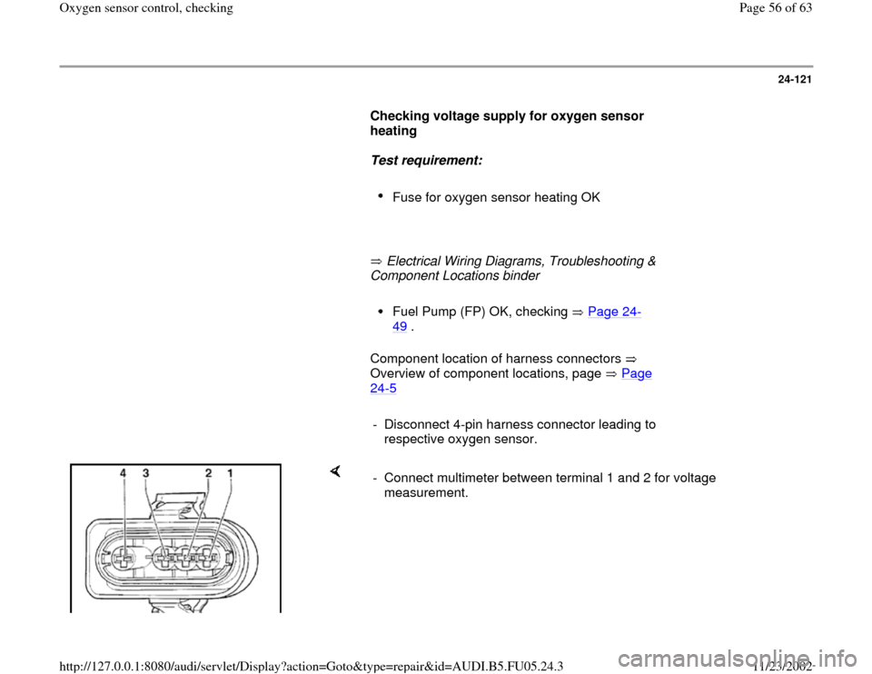
- Disconnect 4-pin harness connector leading to
respective oxygen sensor.
- Connect multimeter between terminal 1 and 2 for voltage
measurement.
Pa
ge 56 of 63 Ox
yg
en sensor control, checkin
g
11/23/2002 htt
p://127.0.0.1:8080/audi/servlet/Dis
play?action=Goto&t
yp
e=re
pair&id=AUDI.B5.FU05.24.3
Page 59 of 63
24-123
If there is no voltage again:
- Check wire connection from terminal 1 to Fuel
Pump (FP) relay via fuse for open circuit.
Electrical Wiring Diagrams, Troubleshooting &
Component Locations binder If voltage supply is OK:
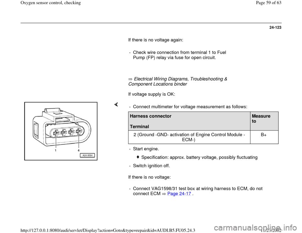
If there is no voltage: - Connect multimeter for voltage measurement as follows:Harness connector
Terminal
Measure
to
2 (Ground -GND- activation of Engine Control Module -
ECM-) B+
- Start engine.
Specification: approx. battery voltage, possibly fluctuating
- Switch ignition off.
- Connect VAG1598/31 test box at wiring harness to ECM, do not
connect ECM Page 24
-17
.
Pa
ge 59 of 63 Ox
yg
en sensor control, checkin
g
11/23/2002 htt
p://127.0.0.1:8080/audi/servlet/Dis
play?action=Goto&t
yp
e=re
pair&id=AUDI.B5.FU05.24.3