tow AUDI A6 1996 C5 / 2.G AEB ATW Engines Exhaust System Components Workshop Manual
[x] Cancel search | Manufacturer: AUDI, Model Year: 1996, Model line: A6, Model: AUDI A6 1996 C5 / 2.GPages: 35, PDF Size: 0.46 MB
Page 3 of 35
26-2
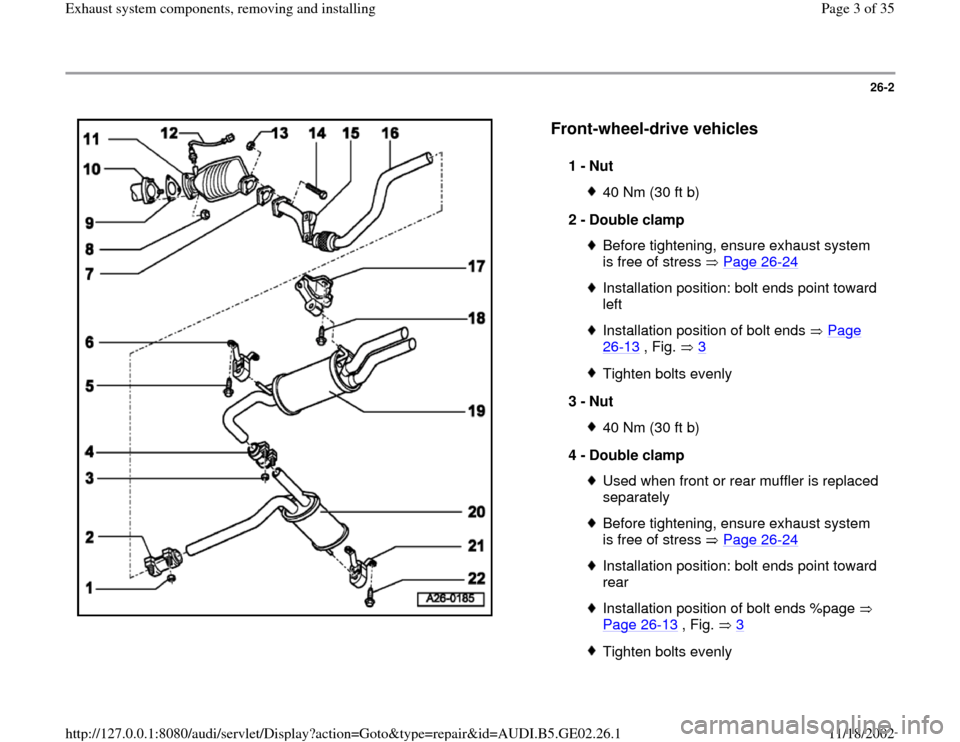
Front-wheel-drive vehicles
1 -
Nut
40 Nm (30 ft b)
2 -
Double clamp Before tightening, ensure exhaust system
is free of stress Page 26
-24
Installation position: bolt ends point toward
left Installation position of bolt ends Page 26
-13
, Fig. 3
Tighten bolts evenly
3 -
Nut 40 Nm (30 ft b)
4 -
Double clamp Used when front or rear muffler is replaced
separately Before tightening, ensure exhaust system
is free of stress Page 26
-24
Installation position: bolt ends point toward
rear Installation position of bolt ends %page
Page 26
-13
, Fig. 3
Tighten bolts evenly
Pa
ge 3 of 35 Exhaust s
ystem com
ponents, removin
g and installin
g
11/18/2002 htt
p://127.0.0.1:8080/audi/servlet/Dis
play?action=Goto&t
yp
e=re
pair&id=AUDI.B5.GE02.26.1
Page 12 of 35
26-9
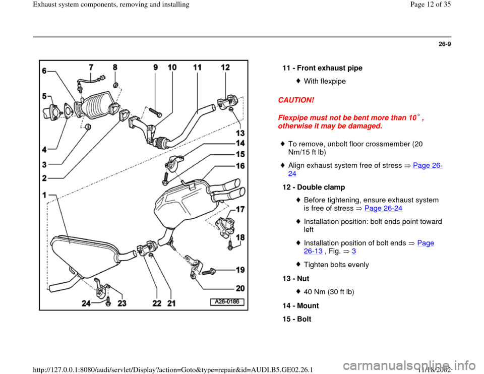
CAUTION!
Flexpipe must not be bent more than 10 ,
otherwise it may be damaged. 11 -
Front exhaust pipe
With flexpipe
To remove, unbolt floor crossmember (20
Nm/15 ft lb)
Align exhaust system free of stress Page 26
-
24
12 -
Double clamp
Before tightening, ensure exhaust system
is free of stress Page 26
-24
Installation position: bolt ends point toward
left Installation position of bolt ends Page 26
-13
, Fig. 3
Tighten bolts evenly
13 -
Nut 40 Nm (30 ft lb)
14 -
Mount
15 -
Bolt
Pa
ge 12 of 35 Exhaust s
ystem com
ponents, removin
g and installin
g
11/18/2002 htt
p://127.0.0.1:8080/audi/servlet/Dis
play?action=Goto&t
yp
e=re
pair&id=AUDI.B5.GE02.26.1
Page 14 of 35
26-10
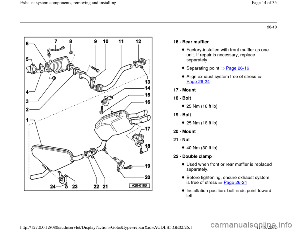
16 -
Rear muffler
Factory-installed with front muffler as one
unit. If repair is necessary, replace
separately Separating point Page 26
-16
Align exhaust system free of stress
Page 26
-24
17 -
Mount
18 -
Bolt
25 Nm (18 ft lb)
19 -
Bolt 25 Nm (18 ft lb)
20 -
Mount
21 -
Nut 40 Nm (30 ft lb)
22 -
Double clamp Used when front or rear muffler is replaced
separately. Before tightening, ensure exhaust system
is free of stress Page 26
-24
Installation position: bolt ends point toward
left
Pa
ge 14 of 35 Exhaust s
ystem com
ponents, removin
g and installin
g
11/18/2002 htt
p://127.0.0.1:8080/audi/servlet/Dis
play?action=Goto&t
yp
e=re
pair&id=AUDI.B5.GE02.26.1
Page 21 of 35
26-16
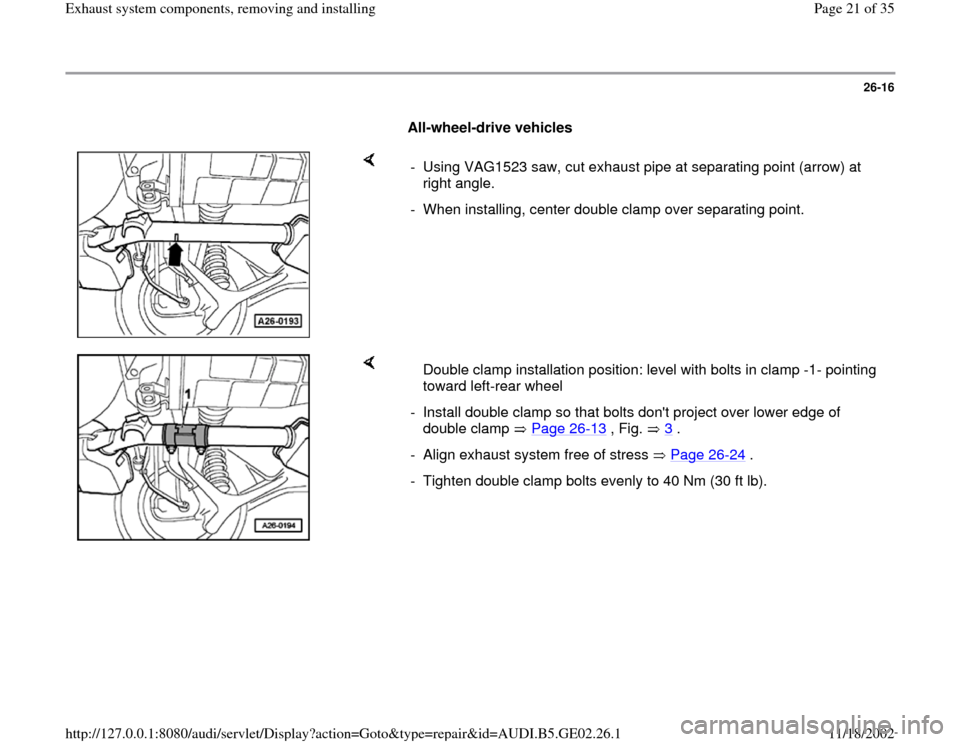
All-wheel-drive vehicles
- Using VAG1523 saw, cut exhaust pipe at separating point (arrow) at
right angle.
- When installing, center double clamp over separating point.
Double clamp installation position: level with bolts in clamp -1- pointing
toward left-rear wheel
- Install double clamp so that bolts don't project over lower edge of
double clamp Page 26
-13
, Fig. 3
.
- Align exhaust system free of stress Page 26
-24
.
- Tighten double clamp bolts evenly to 40 Nm (30 ft lb).
Pa
ge 21 of 35 Exhaust s
ystem com
ponents, removin
g and installin
g
11/18/2002 htt
p://127.0.0.1:8080/audi/servlet/Dis
play?action=Goto&t
yp
e=re
pair&id=AUDI.B5.GE02.26.1
Page 29 of 35
26-22
- Remove air guide duct between cowl and air
cleaner housing.
- Remove air cleaner housing cover.
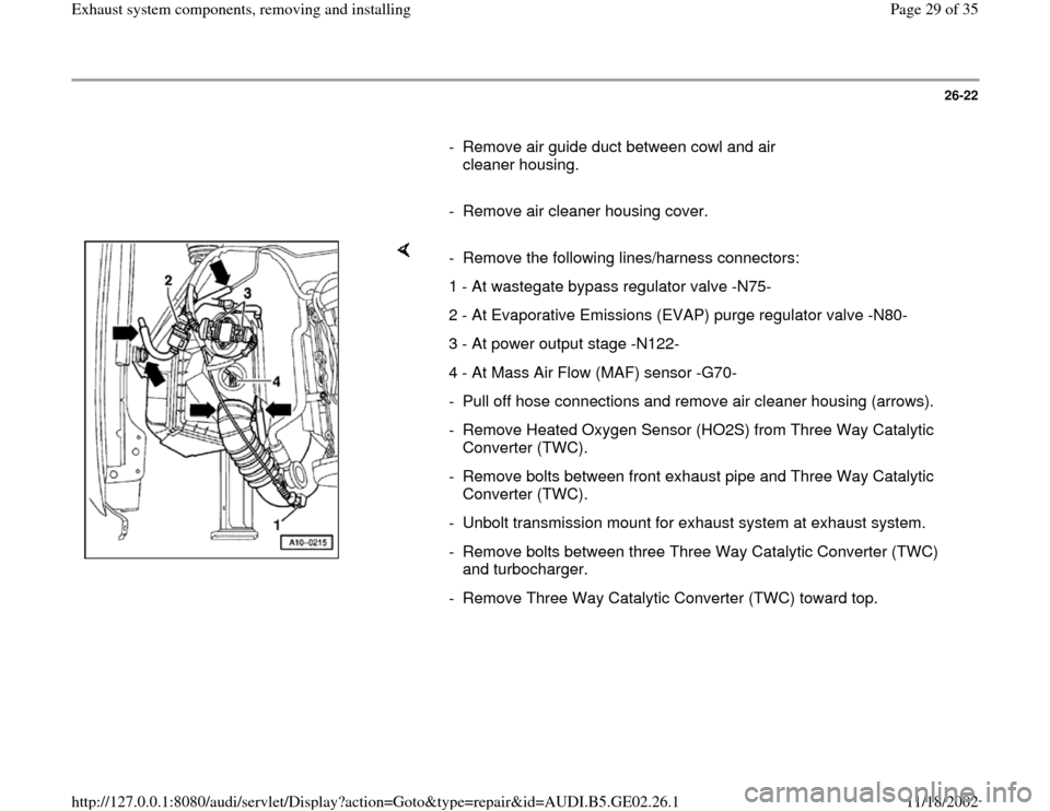
- Remove the following lines/harness connectors:
1 - At wastegate bypass regulator valve -N75-
2 - At Evaporative Emissions (EVAP) purge regulator valve -N80-
3 - At power output stage -N122-
4 - At Mass Air Flow (MAF) sensor -G70-
- Pull off hose connections and remove air cleaner housing (arrows).
- Remove Heated Oxygen Sensor (HO2S) from Three Way Catalytic
Converter (TWC).
- Remove bolts between front exhaust pipe and Three Way Catalytic
Converter (TWC).
- Unbolt transmission mount for exhaust system at exhaust system.
- Remove bolts between three Three Way Catalytic Converter (TWC)
and turbocharger.
- Remove Three Way Catalytic Converter (TWC) toward top.
Pa
ge 29 of 35 Exhaust s
ystem com
ponents, removin
g and installin
g
11/18/2002 htt
p://127.0.0.1:8080/audi/servlet/Dis
play?action=Goto&t
yp
e=re
pair&id=AUDI.B5.GE02.26.1