engine AUDI A6 1997 C5 / 2.G AHA ATQ Engines Secondary Air System Workshop Manual
[x] Cancel search | Manufacturer: AUDI, Model Year: 1997, Model line: A6, Model: AUDI A6 1997 C5 / 2.GPages: 10, PDF Size: 0.17 MB
Page 2 of 10
& Ignition, Repair Group 01
Notes:
The secondary air injection system injects air
behind the exhaust valves during a cold start.
Cold start means engine coolant temperature
between 8-65 C (46-149 F). The amount of
air injected is temperature dependent.
The need for secondary air is triggered by the
Motronic Engine Control Module (ECM) -J220-
via the Secondary Air Injection (AIR) Injection
pump relay -J299- to the Secondary Air
Injection (AIR) solenoid valve -N112- and the
two combination valves.
When "Basic Setting" (scan tool function 04) is
initiated, a diagnosis for the secondary air
injection system can be carried out. The
diagnostics consists of a flow test and a leak
test.
Pa
ge 2 of 10 Secondar
y Air In
jection
(AIR
) system
11/21/2002 htt
p://127.0.0.1:8080/audi/servlet/Dis
play?action=Goto&t
yp
e=re
pair&id=AUDI.B5.GE03.26.2
Page 3 of 10
26-13
Flow test
During the flow test, the oxygen sensor control is
switched off (engine runs rich at that time). At the
same time the secondary air injection pump is
switched on, injecting fresh air into the exhaust
manifold which increases the oxygen content in
the exhaust gas. The oxygen sensor now
measures a lean mixture. To pass the diagnostic
test, the oxygen sensor must measure a lean
mixture for a certain time. Passing the test
means that the secondary air injection system
delivers enough air and the secondary air
injection system is OK.
Leak test
Flow test must check out OK
Engine at operating temperature
The secondary air injection pump is switched on
during idle. Since the combination valves are not
triggered by the secondary air injection solenoid
valve, they remain closed. When the secondary
air injection pump is switched on, the oxygen
sensor system is monitored by the ECM. If the
system does not leak, fresh air cannot enter the
exhaust manifold. If the system is leaking, the
oxygen sensor signal will respond to the leaner
mixture (caused by the secondary air getting into
the exhaust manifold) and cause a noticeable
Pa
ge 3 of 10 Secondar
y Air In
jection
(AIR
) system
11/21/2002 htt
p://127.0.0.1:8080/audi/servlet/Dis
play?action=Goto&t
yp
e=re
pair&id=AUDI.B5.GE03.26.2
Page 5 of 10
26-14
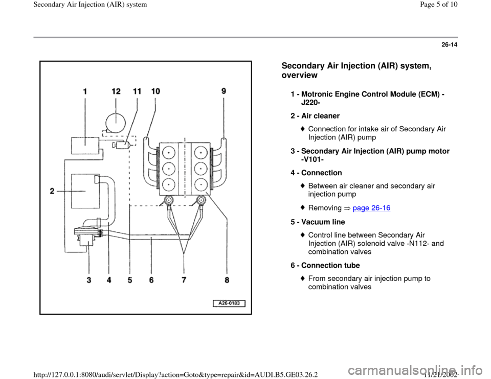
Secondary Air Injection (AIR) system,
overview
1 -
Motronic Engine Control Module (ECM) -
J220-
2 -
Air cleaner
Connection for intake air of Secondary Air
Injection (AIR) pump
3 -
Secondary Air Injection (AIR) pump motor
-V101-
4 -
Connection Between air cleaner and secondary air
injection pump Removing page 26
-16
5 -
Vacuum line
Control line between Secondary Air
Injection (AIR) solenoid valve -N112- and
combination valves
6 -
Connection tube From secondary air injection pump to
combination valves
Pa
ge 5 of 10 Secondar
y Air In
jection
(AIR
) system
11/21/2002 htt
p://127.0.0.1:8080/audi/servlet/Dis
play?action=Goto&t
yp
e=re
pair&id=AUDI.B5.GE03.26.2
Page 6 of 10
26-15
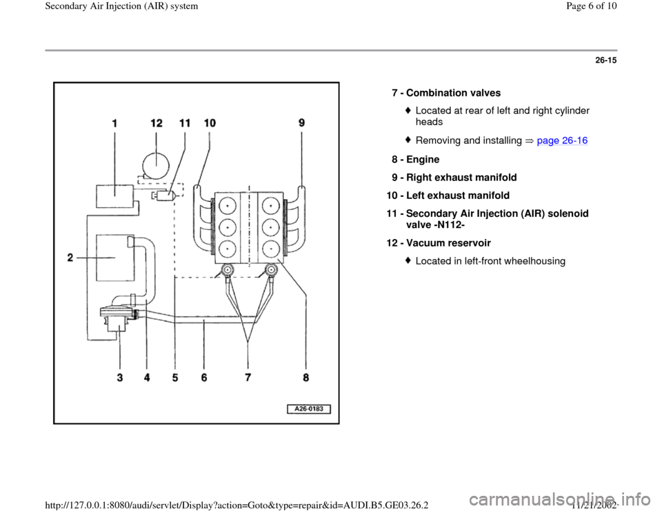
7 -
Combination valves
Located at rear of left and right cylinder
heads Removing and installing page 26
-16
8 -
Engine
9 -
Right exhaust manifold
10 -
Left exhaust manifold
11 -
Secondary Air Injection (AIR) solenoid
valve -N112-
12 -
Vacuum reservoir
Located in left-front wheelhousing
Pa
ge 6 of 10 Secondar
y Air In
jection
(AIR
) system
11/21/2002 htt
p://127.0.0.1:8080/audi/servlet/Dis
play?action=Goto&t
yp
e=re
pair&id=AUDI.B5.GE03.26.2
Page 7 of 10
26-16
Secondary Air Injection (AIR) system
components, removing and installing
Component locations page 26
-14
.
Fuel injection and ignition components.
Repair Manual, 2.8 Liter V6 5V Fuel Injection
& Ignition, Repair Group 24
Note:
Always replace gaskets and seals.
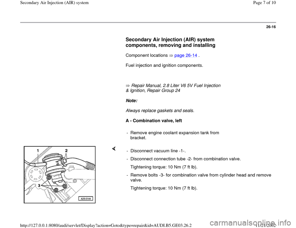
A - Combination valve, left
- Remove engine coolant expansion tank from
bracket.
- Disconnect vacuum line -1-.
- Disconnect connection tube -2- from combination valve.
Tightening torque: 10 Nm (7 ft lb).
- Remove bolts -3- for combination valve from cylinder head and remove
valve.
Tightening torque: 10 Nm (7 ft lb).
Pa
ge 7 of 10 Secondar
y Air In
jection
(AIR
) system
11/21/2002 htt
p://127.0.0.1:8080/audi/servlet/Dis
play?action=Goto&t
yp
e=re
pair&id=AUDI.B5.GE03.26.2