engine AUDI A6 1997 C5 / 2.G ATQ Engine Motronic Injection System Servicing Owner's Guide
[x] Cancel search | Manufacturer: AUDI, Model Year: 1997, Model line: A6, Model: AUDI A6 1997 C5 / 2.GPages: 78, PDF Size: 1 MB
Page 56 of 78
24-47
Checking Proper Seal
- Check proper seal of fuel injectors (visual
inspection). With Fuel Pump (FP) running, only 1
to 2 drops per minute may drip out per injector.
- If fuel loss is greater, stop Fuel Pump (FP) from
running (disconnect cable bridge) and replace
faulty fuel injector Page 24
-43
.
Checking Injection Quantity
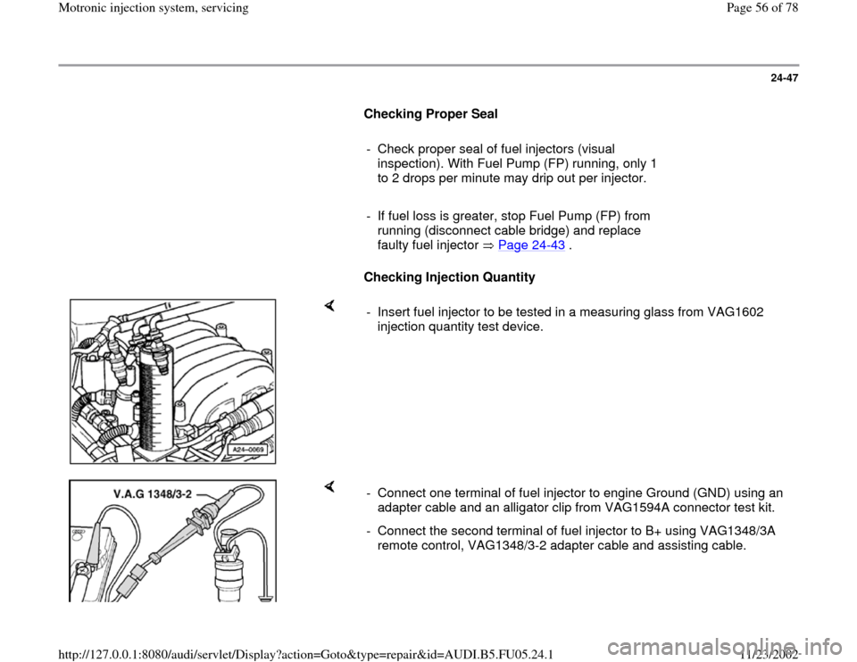
- Insert fuel injector to be tested in a measuring glass from VAG1602
injection quantity test device.
- Connect one terminal of fuel injector to engine Ground (GND) using an
adapter cable and an alligator clip from VAG1594A connector test kit.
- Connect the second terminal of fuel injector to B+ using VAG1348/3A
remote control, VAG1348/3-2 adapter cable and assisting cable.
Pa
ge 56 of 78 Motronic in
jection s
ystem, servicin
g
11/23/2002 htt
p://127.0.0.1:8080/audi/servlet/Dis
play?action=Goto&t
yp
e=re
pair&id=AUDI.B5.FU05.24.1
Page 60 of 78
24-50
Voltage is supplied to the Fuel Pump (FP) and
several components of the injection system via
the Fuel Pump (FP) relay -J17-.
Engine must be turning for Fuel Pump (FP) relay
-J17- to close. This means that the relay does
not receive Ground (GND) (via ECM) until the
ECM recognizes RPM signals.
Note:
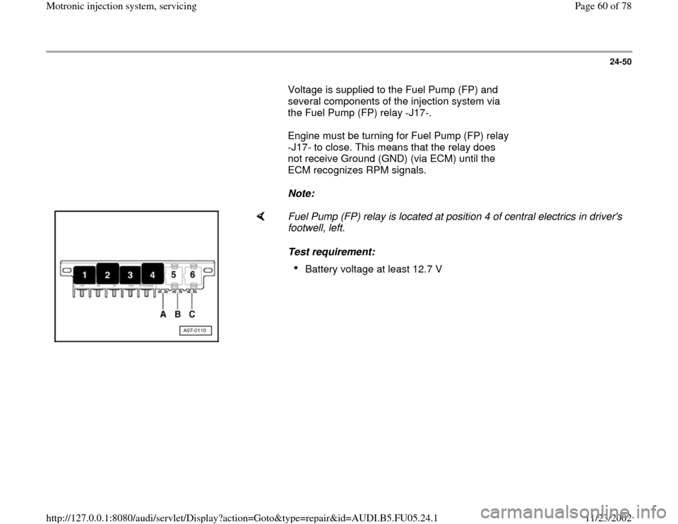
Fuel Pump (FP) relay is located at position 4 of central electrics in driver's
footwell, left.
Test requirement:
Battery voltage at least 12.7 V
Pa
ge 60 of 78 Motronic in
jection s
ystem, servicin
g
11/23/2002 htt
p://127.0.0.1:8080/audi/servlet/Dis
play?action=Goto&t
yp
e=re
pair&id=AUDI.B5.FU05.24.1
Page 61 of 78
24-51
Function test of Fuel Pump (FP) relay
- Remove driver-side storage compartment.
Repair Manual, Body
-Interior, Repair Group
68; Instrument Panel; Removing Driver
-Side
Storage Compartment
- Connect VAS5051 tester or VAG1551 scan tool
and select the control module for engine
electronics using "address word" 01 Page 01
-
9 .
Ignition must remain switched on for this.
- Initiate output Diagnostic Test Mode Page 01
-
56
and activate Evaporative Emission (EVAP)
canister purge regulator valve -N80-.
A - If relay does not trigger:
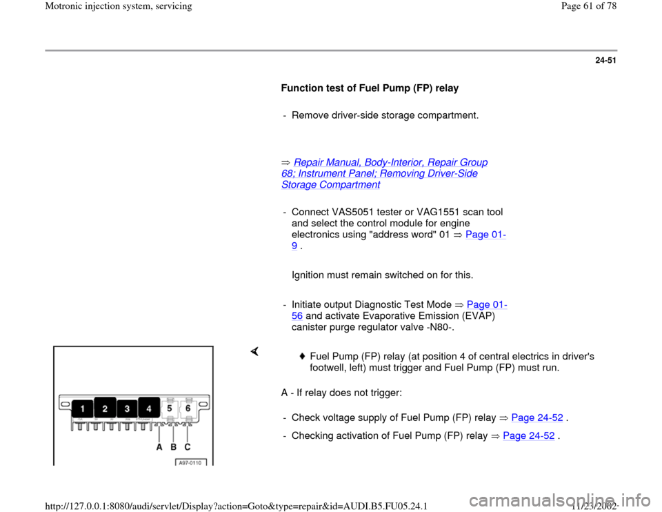
Fuel Pump (FP) relay (at position 4 of central electrics in driver's
footwell, left) must trigger and Fuel Pump (FP) must run.
- Check voltage supply of Fuel Pump (FP) relay Page 24
-52
.
- Checking activation of Fuel Pump (FP) relay Page 24
-52
.Pa
ge 61 of 78 Motronic in
jection s
ystem, servicin
g
11/23/2002 htt
p://127.0.0.1:8080/audi/servlet/Dis
play?action=Goto&t
yp
e=re
pair&id=AUDI.B5.FU05.24.1
Page 63 of 78
24-53
If relay triggers now, but didn't during output DTM:
If relay does not trigger:
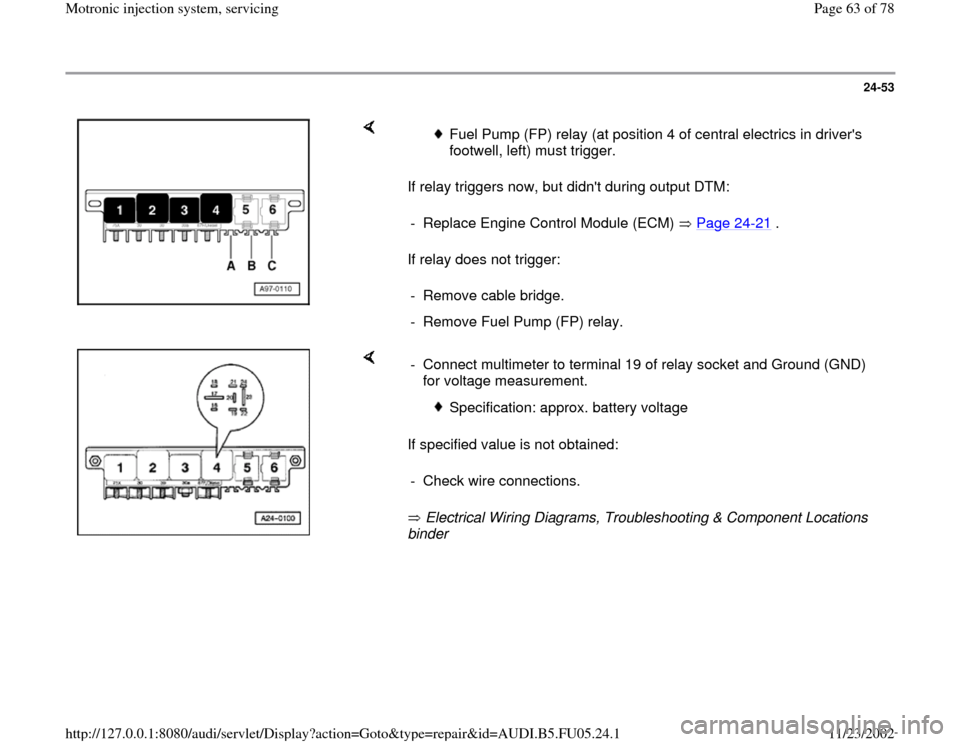
Fuel Pump (FP) relay (at position 4 of central electrics in driver's
footwell, left) must trigger.
- Replace Engine Control Module (ECM) Page 24
-21
.
- Remove cable bridge.
- Remove Fuel Pump (FP) relay.
If specified value is not obtained:
Electrical Wiring Diagrams, Troubleshooting & Component Locations
binder - Connect multimeter to terminal 19 of relay socket and Ground (GND)
for voltage measurement.
Specification: approx. battery voltage
- Check wire connections.
Pa
ge 63 of 78 Motronic in
jection s
ystem, servicin
g
11/23/2002 htt
p://127.0.0.1:8080/audi/servlet/Dis
play?action=Goto&t
yp
e=re
pair&id=AUDI.B5.FU05.24.1
Page 64 of 78
24-54
If specified value is obtained:
If no malfunctions are detected:
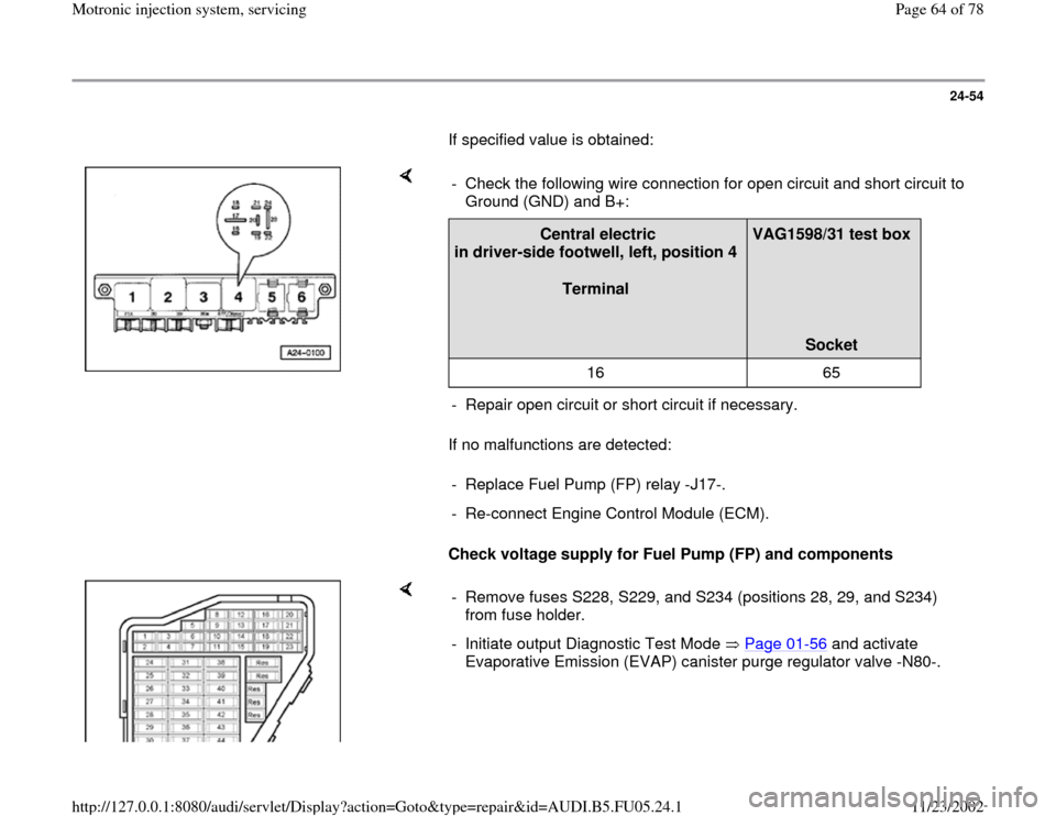
Check voltage supply for Fuel Pump (FP) and components - Check the following wire connection for open circuit and short circuit to
Ground (GND) and B+:
Central electric
in driver-side footwell, left, position 4
Terminal
VAG1598/31 test box
Socket
16 65
- Repair open circuit or short circuit if necessary.
- Replace Fuel Pump (FP) relay -J17-.
- Re-connect Engine Control Module (ECM).
- Remove fuses S228, S229, and S234 (positions 28, 29, and S234)
from fuse holder.
- Initiate output Diagnostic Test Mode Page 01
-56
and activate
Evaporative Emission (EVAP) canister purge regulator valve -N80-.
Pa
ge 64 of 78 Motronic in
jection s
ystem, servicin
g
11/23/2002 htt
p://127.0.0.1:8080/audi/servlet/Dis
play?action=Goto&t
yp
e=re
pair&id=AUDI.B5.FU05.24.1
Page 67 of 78
24-57
Test requirements:
Coolant Temperature at least 80 C.
Electrical consumers switched off (radiator
fan must NOT run during test).
A/C switched off.
Fuse for Mass Air Flow (MAF) sensor OK
Electrical Wiring Diagrams, Troubleshooting &
Component Locations binder
Checking function
- Connect VAS5051 tester or VAG1551 scan tool
and select the control module for engine
electronics using "address word" 01 Page 01
-
9 .
Engine must run at idle for this.Rapid data transfer
HELP
Select function XX
When indicated on display:
-
Press buttons -0- and -4- to select "Initiate basic setting" and press -Q-
Pa
ge 67 of 78 Motronic in
jection s
ystem, servicin
g
11/23/2002 htt
p://127.0.0.1:8080/audi/servlet/Dis
play?action=Goto&t
yp
e=re
pair&id=AUDI.B5.FU05.24.1
Page 69 of 78
24-58
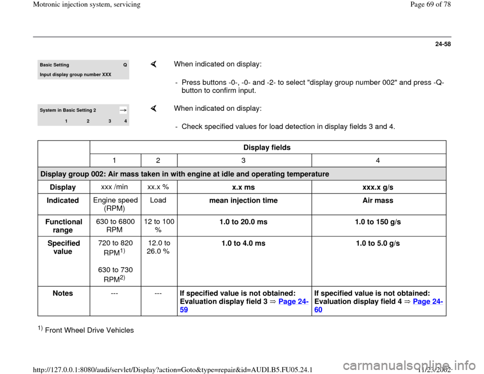
Basic Settin
g
Q
Input display group number XXX
When indicated on display:
- Press buttons -0-, -0- and -2- to select "display group number 002" and press -Q-
button to confirm input.
System in Basic Setting 2
1
2
3
4
When indicated on display:
- Check specified values for load detection in display fields 3 and 4.
Display fields
1 2 3 4
Display group 002: Air mass taken in with engine at idle and operating temperature
Display xxx /min xx.x %
x.x ms
xxx.x g/s
Indicated Engine speed
(RPM) Load
mean injection time
Air mass
Functional
range 630 to 6800
RPM 12 to 100
% 1.0 to 20.0 ms
1.0 to 150 g/s
Specified
value 720 to 820
RPM
1)
630 to 730
RPM2) 12.0 to
26.0 % 1.0 to 4.0 ms
1.0 to 5.0 g/s
Notes --- ---
If specified value is not obtained:
Evaluation display field 3 Page 24
-
59
If specified value is not obtained:
Evaluation display field 4 Page 24
-
60
1) Front Wheel Drive Vehicles
Pa
ge 69 of 78 Motronic in
jection s
ystem, servicin
g
11/23/2002 htt
p://127.0.0.1:8080/audi/servlet/Dis
play?action=Goto&t
yp
e=re
pair&id=AUDI.B5.FU05.24.1
Page 71 of 78
24-59
If specified values are obtained:
-
Press button.Rapid data transfer
HELP
Select function XX
Indicated on display (function selection):
Evaluation display group 002
Display field: 3
Possible cause
Corrective action
less than 1.0
ms
Smaller values are only possible when driving in
deceleration mode
larger than 4.0
ms Engine under load due to power accessories.- Reduce load (A/C system/power
steering/generator)
Poor idle (does not run on all cylinders)- Check spark plugs.
- Check fuel injectors Page 24
-36
Throttle valve control module - J338- faulty- Check throttle valve control module Page
24
-141
Pa
ge 71 of 78 Motronic in
jection s
ystem, servicin
g
11/23/2002 htt
p://127.0.0.1:8080/audi/servlet/Dis
play?action=Goto&t
yp
e=re
pair&id=AUDI.B5.FU05.24.1
Page 72 of 78
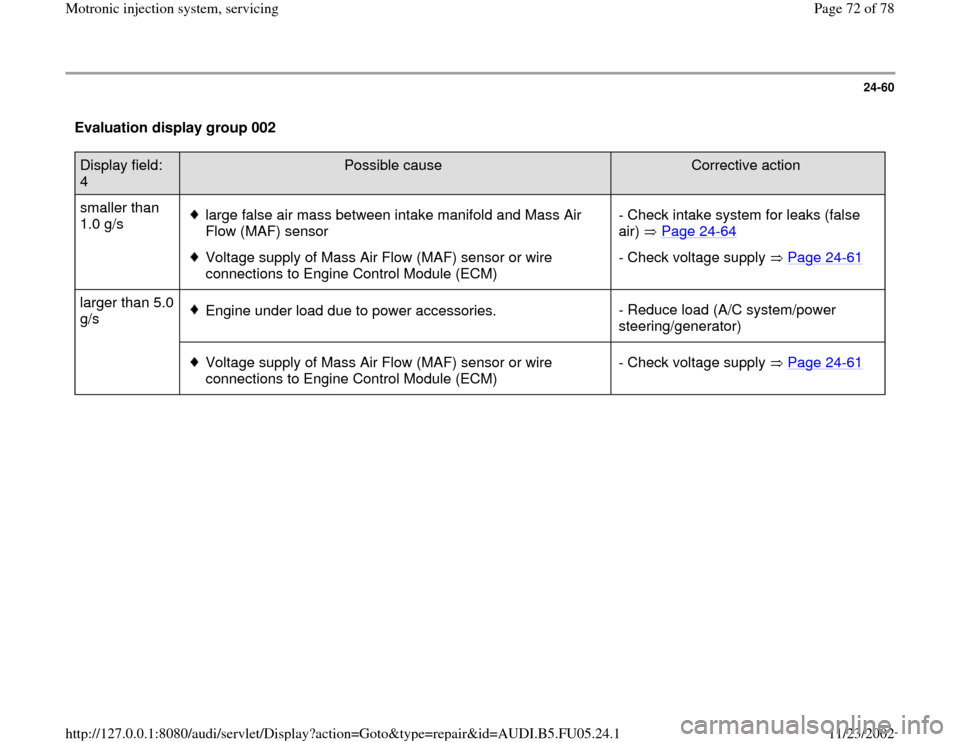
24-60
Evaluation display group 002 Display field:
4
Possible cause
Corrective action
smaller than
1.0 g/s
large false air mass between intake manifold and Mass Air
Flow (MAF) sensor
Voltage supply of Mass Air Flow (MAF) sensor or wire
connections to Engine Control Module (ECM) - Check intake system for leaks (false
air) Page 24
-64
- Check voltage supply Page 24
-61
larger than 5.0
g/s
Engine under load due to power accessories.- Reduce load (A/C system/power
steering/generator)
Voltage supply of Mass Air Flow (MAF) sensor or wire
connections to Engine Control Module (ECM) - Check voltage supply Page 24
-61
Pa
ge 72 of 78 Motronic in
jection s
ystem, servicin
g
11/23/2002 htt
p://127.0.0.1:8080/audi/servlet/Dis
play?action=Goto&t
yp
e=re
pair&id=AUDI.B5.FU05.24.1
Page 73 of 78
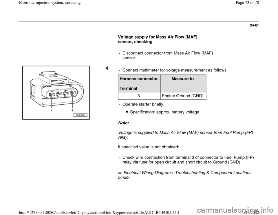
24-61
Voltage supply for Mass Air Flow (MAF)
sensor, checking
- Disconnect connector from Mass Air Flow (MAF)
sensor.
Note:
Voltage is supplied to Mass Air Flow (MAF) sensor from Fuel Pump (FP)
relay.
If specified value is not obtained:
Electrical Wiring Diagrams, Troubleshooting & Component Locations
binder - Connect multimeter for voltage measurement as follows.Harness connector
Terminal
Measure to
3 Engine Ground (GND)
- Operate starter briefly.
Specification: approx. battery voltage
- Check wire connection from terminal 3 of connector to Fuel Pump (FP)
relay via fuse for open circuit and short circuit to Ground (GND):
Pa
ge 73 of 78 Motronic in
jection s
ystem, servicin
g
11/23/2002 htt
p://127.0.0.1:8080/audi/servlet/Dis
play?action=Goto&t
yp
e=re
pair&id=AUDI.B5.FU05.24.1