open AUDI A6 1997 C5 / 2.G ATW Engine Ignition System Workshop Manual
[x] Cancel search | Manufacturer: AUDI, Model Year: 1997, Model line: A6, Model: AUDI A6 1997 C5 / 2.GPages: 59, PDF Size: 0.53 MB
Page 13 of 59
28-12
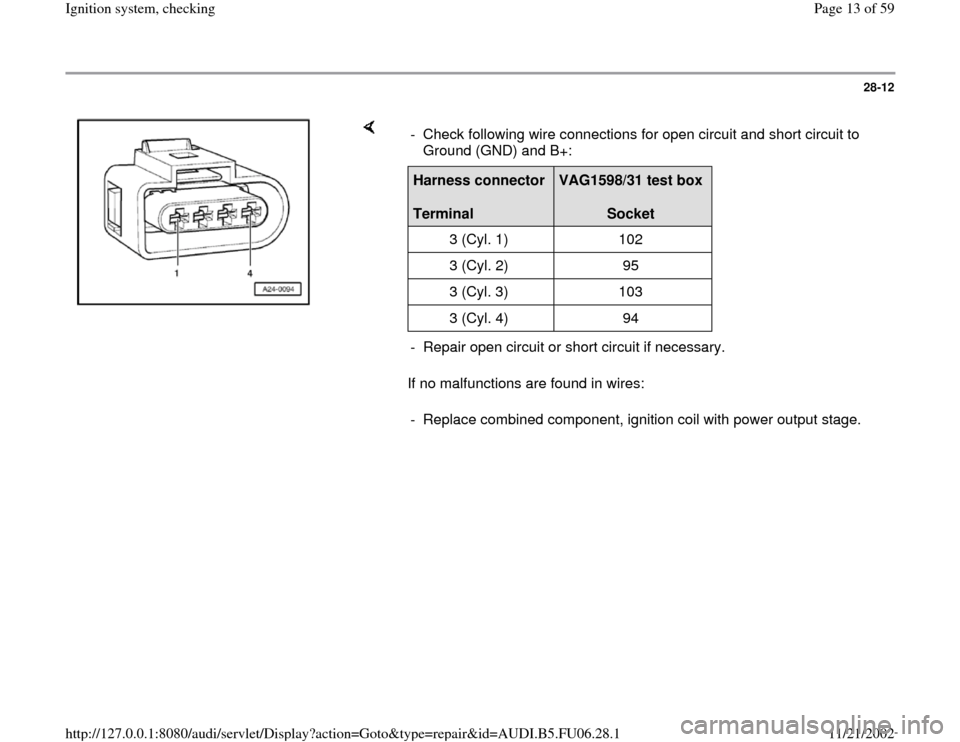
If no malfunctions are found in wires: - Check following wire connections for open circuit and short circuit to
Ground (GND) and B+: Harness connector
Terminal
VAG1598/31 test box
Socket
3 (Cyl. 1) 102
3 (Cyl. 2) 95
3 (Cyl. 3) 103
3 (Cyl. 4) 94
- Repair open circuit or short circuit if necessary.
- Replace combined component, ignition coil with power output stage.
Pa
ge 13 of 59 I
gnition s
ystem, checkin
g
11/21/2002 htt
p://127.0.0.1:8080/audi/servlet/Dis
play?action=Goto&t
yp
e=re
pair&id=AUDI.B5.FU06.28.1
Page 18 of 59
28-17
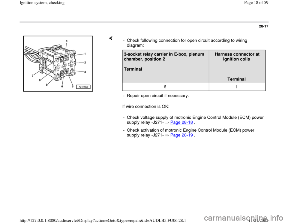
If wire connection is OK: - Check following connection for open circuit according to wiring
diagram: 3-socket relay carrier in E-box, plenum
chamber, position 2
Terminal
Harness connector at
ignition coils
Terminal
6 1
- Repair open circuit if necessary.
- Check voltage supply of motronic Engine Control Module (ECM) power
supply relay -J271- Page 28
-18
.
- Check activation of motronic Engine Control Module (ECM) power
supply relay -J271- Page 28
-19
.
Pa
ge 18 of 59 I
gnition s
ystem, checkin
g
11/21/2002 htt
p://127.0.0.1:8080/audi/servlet/Dis
play?action=Goto&t
yp
e=re
pair&id=AUDI.B5.FU06.28.1
Page 19 of 59
28-18
Checking voltage supply
If specified value is not obtained:
Electrical Wiring Diagrams, Troubleshooting & Component Locations
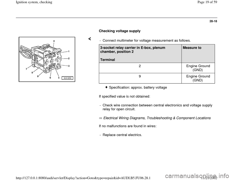
If no malfunctions are found in wires: - Connect multimeter for voltage measurement as follows.3-socket relay carrier in E-box, plenum
chamber, position 2
Terminal
Measure to
2 Engine Ground
(GND)
9 Engine Ground
(GND)
Specification: approx. battery voltage
- Check wire connection between central electronics and voltage supply
relay for open circuit.
- Replace central electrics.
Pa
ge 19 of 59 I
gnition s
ystem, checkin
g
11/21/2002 htt
p://127.0.0.1:8080/audi/servlet/Dis
play?action=Goto&t
yp
e=re
pair&id=AUDI.B5.FU06.28.1
Page 21 of 59
28-20
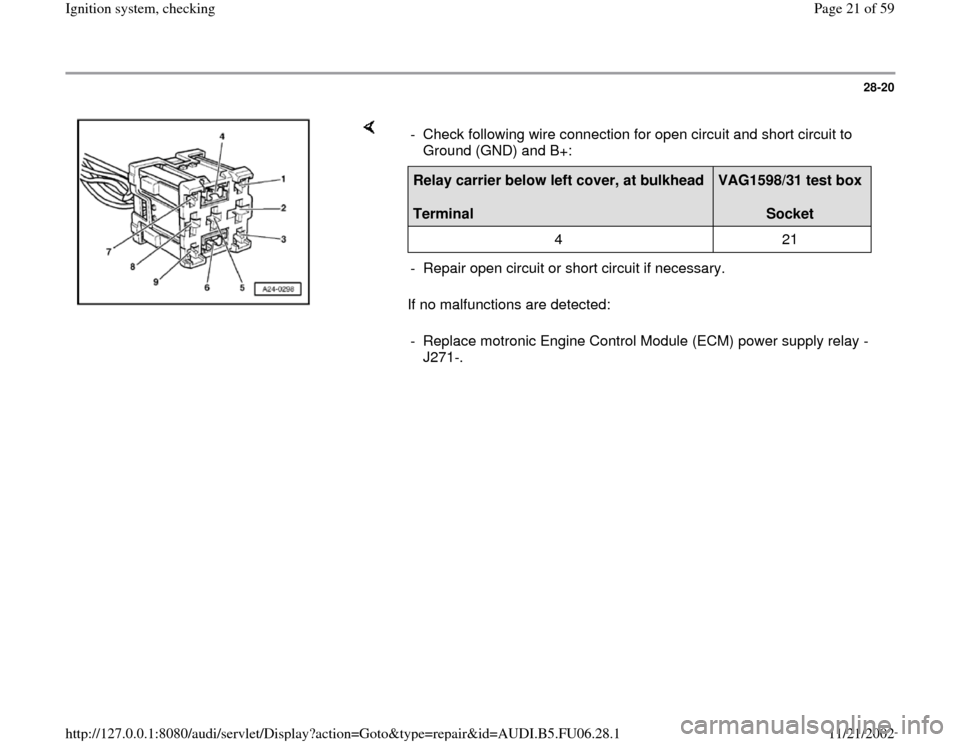
If no malfunctions are detected: - Check following wire connection for open circuit and short circuit to
Ground (GND) and B+: Relay carrier below left cover, at bulkhead
Terminal
VAG1598/31 test box
Socket
4 21
- Repair open circuit or short circuit if necessary.
- Replace motronic Engine Control Module (ECM) power supply relay -
J271-.
Pa
ge 21 of 59 I
gnition s
ystem, checkin
g
11/21/2002 htt
p://127.0.0.1:8080/audi/servlet/Dis
play?action=Goto&t
yp
e=re
pair&id=AUDI.B5.FU06.28.1
Page 24 of 59
28-23
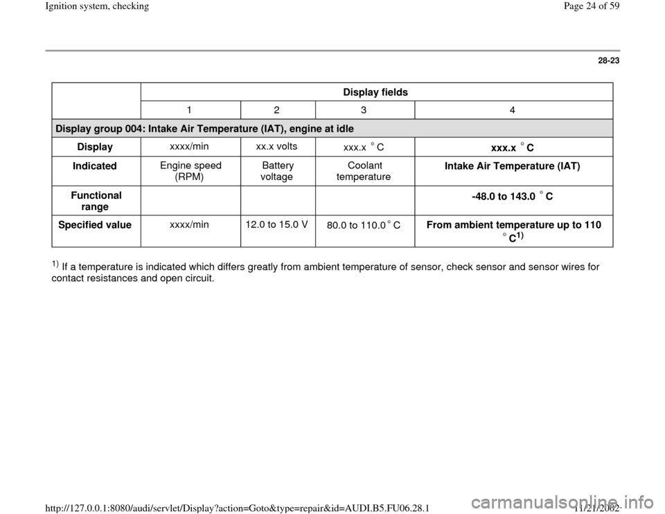
Display fields
1 2 3 4
Display group 004: Intake Air Temperature (IAT), engine at idle
Display xxxx/min xx.x volts
xxx.x C
xxx.x C
Indicated Engine speed
(RPM) Battery
voltage Coolant
temperature Intake Air Temperature (IAT)
Functional
range
-48.0 to 143.0 C
Specified value xxxx/min 12.0 to 15.0 V
80.0 to 110.0 C
From ambient temperature up to 110
C
1)
1) If a temperature is indicated which differs greatly from ambient temperature of sensor, check sensor and sensor wires for
contact resistances and open circuit.
Pa
ge 24 of 59 I
gnition s
ystem, checkin
g
11/21/2002 htt
p://127.0.0.1:8080/audi/servlet/Dis
play?action=Goto&t
yp
e=re
pair&id=AUDI.B5.FU06.28.1
Page 25 of 59
28-24
Checking wire connections
- Connect VAG1598/31 test box at wiring harness
to Engine Control Module (ECM), do not connect
ECM Page 24
-19
.
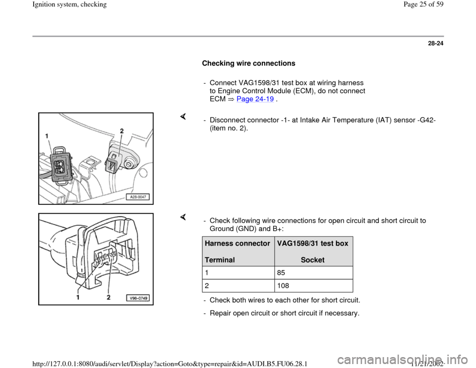
- Disconnect connector -1- at Intake Air Temperature (IAT) sensor -G42-
(item no. 2).
- Check following wire connections for open circuit and short circuit to
Ground (GND) and B+: Harness connector
Terminal
VAG1598/31 test box
Socket
1 85
2 108
- Check both wires to each other for short circuit.
- Repair open circuit or short circuit if necessary.
Pa
ge 25 of 59 I
gnition s
ystem, checkin
g
11/21/2002 htt
p://127.0.0.1:8080/audi/servlet/Dis
play?action=Goto&t
yp
e=re
pair&id=AUDI.B5.FU06.28.1
Page 30 of 59
28-29
If specified value is obtained:
- Connect VAG1598/31 test box at wiring harness
to Engine Control Module (ECM), do not connect
ECM Page 24
-19
.
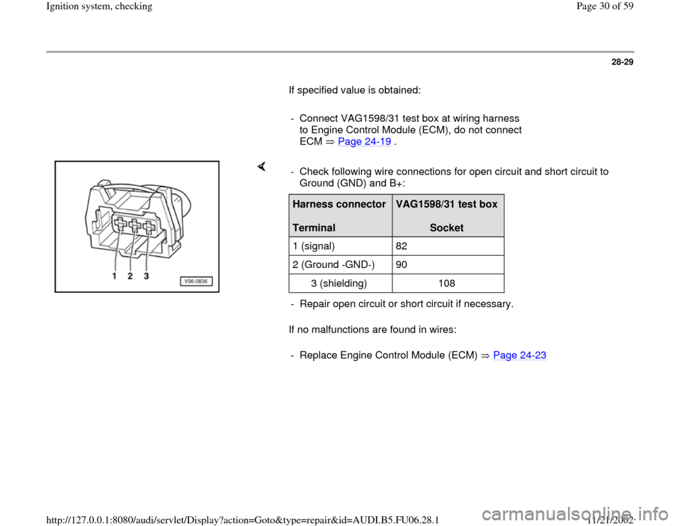
If no malfunctions are found in wires: - Check following wire connections for open circuit and short circuit to
Ground (GND) and B+: Harness connector
Terminal
VAG1598/31 test box
Socket
1 (signal) 82
2 (Ground -GND-) 90
3 (shielding) 108
- Repair open circuit or short circuit if necessary.
- Replace Engine Control Module (ECM) Page 24
-23
Pa
ge 30 of 59 I
gnition s
ystem, checkin
g
11/21/2002 htt
p://127.0.0.1:8080/audi/servlet/Dis
play?action=Goto&t
yp
e=re
pair&id=AUDI.B5.FU06.28.1
Page 35 of 59
28-34
If specified value is obtained:
- Connect VAG1598/31 test box at wiring harness
to Engine Control Module (ECM), do not connect
ECM Page 24
-19
.
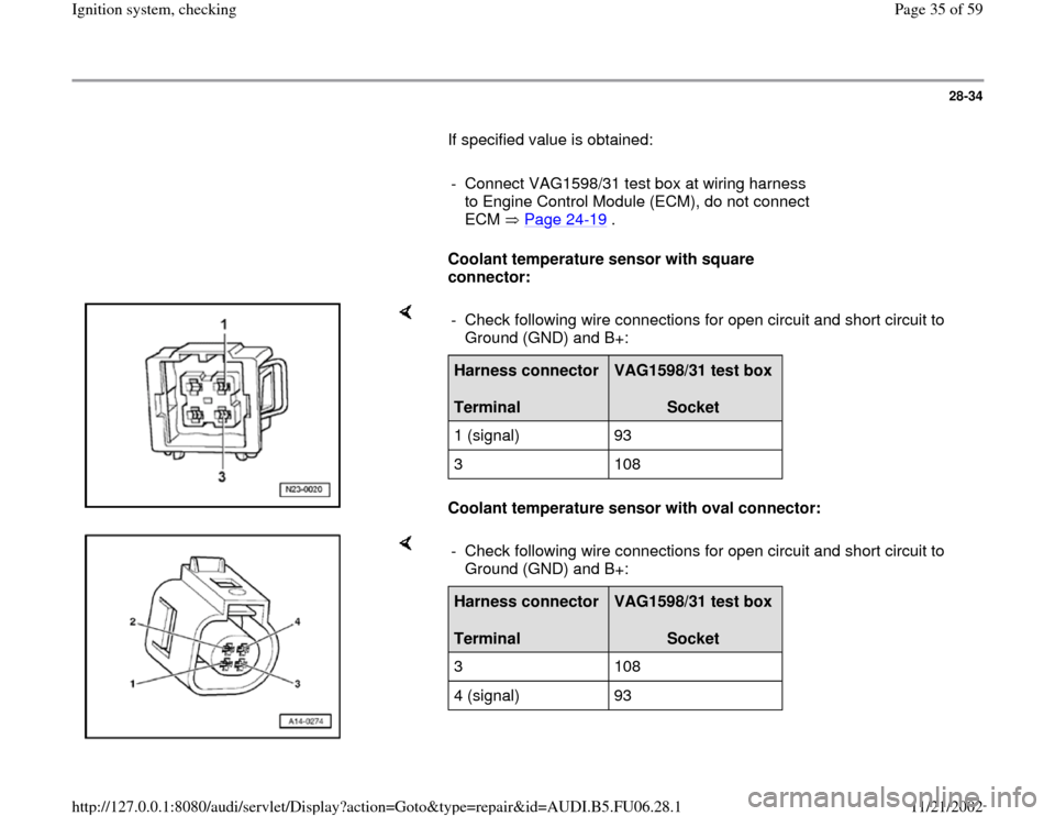
Coolant temperature sensor with square
connector:
Coolant temperature sensor with oval connector: - Check following wire connections for open circuit and short circuit to
Ground (GND) and B+: Harness connector
Terminal
VAG1598/31 test box
Socket
1 (signal) 93
3 108
- Check following wire connections for open circuit and short circuit to
Ground (GND) and B+: Harness connector
Terminal
VAG1598/31 test box
Socket
3 108
4 (signal) 93
Pa
ge 35 of 59 I
gnition s
ystem, checkin
g
11/21/2002 htt
p://127.0.0.1:8080/audi/servlet/Dis
play?action=Goto&t
yp
e=re
pair&id=AUDI.B5.FU06.28.1
Page 36 of 59

28-35
All models:
- Check both wires to each other for short
circuit.
- Repair open circuit or short circuit if
necessary.
If no malfunctions are found in wires:
- Replace Engine Control Module (ECM) Page
24
-23
Pa
ge 36 of 59 I
gnition s
ystem, checkin
g
11/21/2002 htt
p://127.0.0.1:8080/audi/servlet/Dis
play?action=Goto&t
yp
e=re
pair&id=AUDI.B5.FU06.28.1
Page 47 of 59
28-43
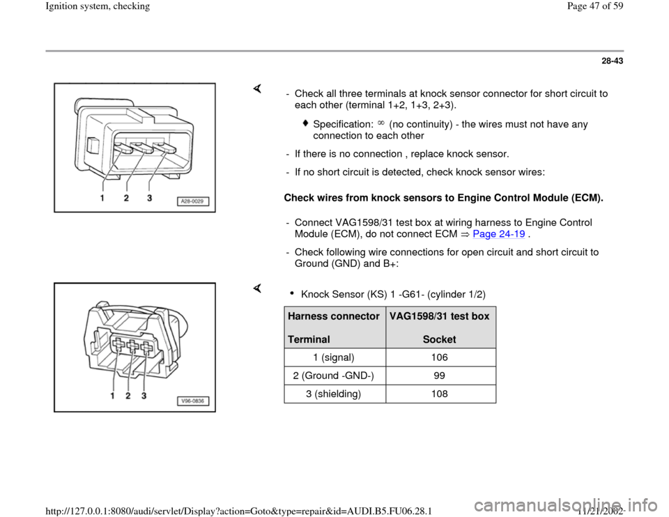
Check wires from knock sensors to Engine Control Module (ECM). - Check all three terminals at knock sensor connector for short circuit to
each other (terminal 1+2, 1+3, 2+3).
Specification: (no continuity) - the wires must not have any
connection to each other
- If there is no connection , replace knock sensor.
- If no short circuit is detected, check knock sensor wires:
- Connect VAG1598/31 test box at wiring harness to Engine Control
Module (ECM), do not connect ECM Page 24
-19
.
- Check following wire connections for open circuit and short circuit to
Ground (GND) and B+:
Knock Sensor (KS) 1 -G61- (cylinder 1/2)
Harness connector
Terminal
VAG1598/31 test box
Socket
1 (signal) 106
2 (Ground -GND-) 99
3 (shielding) 108
Pa
ge 47 of 59 I
gnition s
ystem, checkin
g
11/21/2002 htt
p://127.0.0.1:8080/audi/servlet/Dis
play?action=Goto&t
yp
e=re
pair&id=AUDI.B5.FU06.28.1