AUDI A6 1998 C5 / 2.G 01V Transmission Select Lever Mechanism Service Manual
Manufacturer: AUDI, Model Year: 1998, Model line: A6, Model: AUDI A6 1998 C5 / 2.GPages: 75, PDF Size: 0.76 MB
Page 41 of 75
37-36
Selector lever, disassembling and
assembling
- Remove selector lever page 37
-32
.
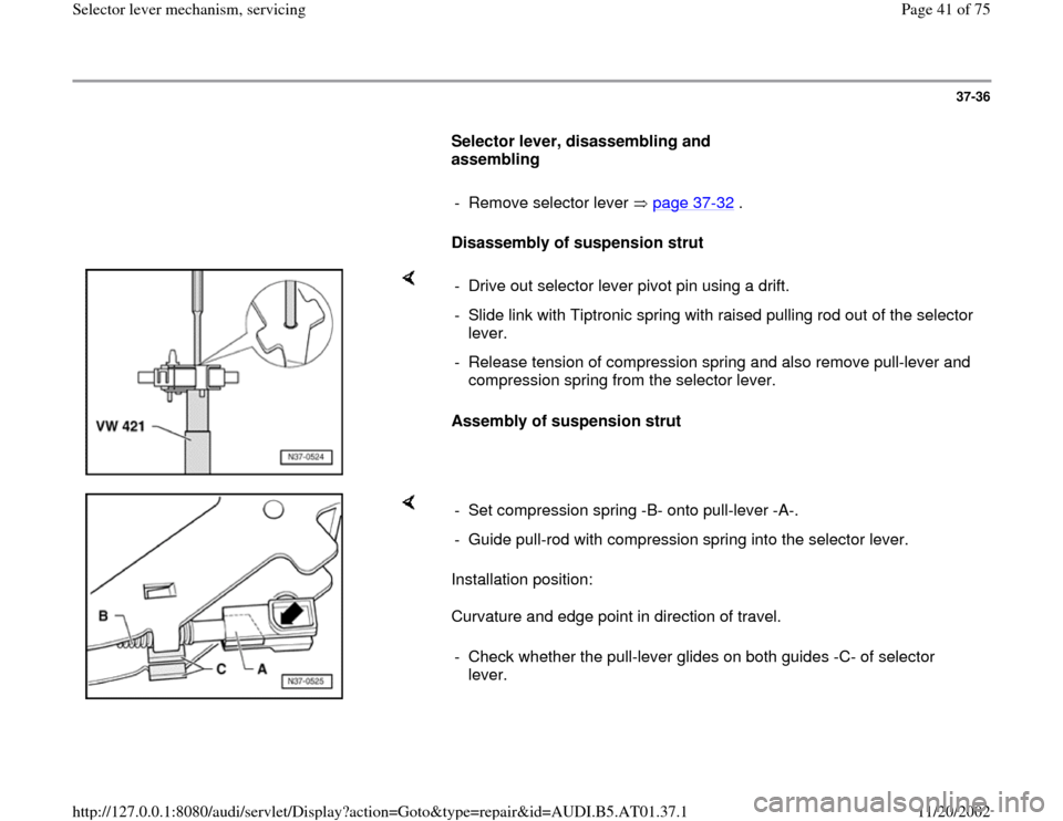
Disassembly of suspension strut
Assembly of suspension strut - Drive out selector lever pivot pin using a drift.
- Slide link with Tiptronic spring with raised pulling rod out of the selector
lever.
- Release tension of compression spring and also remove pull-lever and
compression spring from the selector lever.
Installation position:
Curvature and edge point in direction of travel. - Set compression spring -B- onto pull-lever -A-.
- Guide pull-rod with compression spring into the selector lever.
- Check whether the pull-lever glides on both guides -C- of selector
lever.
Pa
ge 41 of 75 Selector lever mechanism, servicin
g
11/20/2002 htt
p://127.0.0.1:8080/audi/servlet/Dis
play?action=Goto&t
yp
e=re
pair&id=AUDI.B5.AT01.37.1
Page 42 of 75
37-37
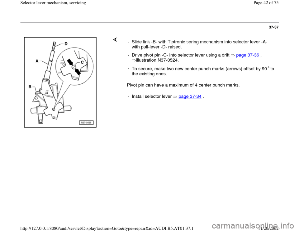
Pivot pin can have a maximum of 4 center punch marks. - Slide link -B- with Tiptronic spring mechanism into selector lever -A-
with pull-lever -D- raised.
- Drive pivot pin -C- into selector lever using a drift page 37
-36
,
illustration N37-0524.
-
To secure, make two new center punch marks (arrows) offset by 90 to
the existing ones. - Install selector lever page 37
-34
.
Pa
ge 42 of 75 Selector lever mechanism, servicin
g
11/20/2002 htt
p://127.0.0.1:8080/audi/servlet/Dis
play?action=Goto&t
yp
e=re
pair&id=AUDI.B5.AT01.37.1
Page 43 of 75
37-38
Shift lock solenoid, removing and installing
Removing
- Remove shift mechanism page 37
-6 .
- Remove stop buffer from cable lever.
- Shift selector lever into Tiptronic position and
then remove frame.
- Shift selector lever into position "2".
- Disengage lever for locking cable by lifting it out
of its bearing and remove from shift mechanism
housing.
- Press out pin for locking latch using a drift.
- Remove shift lock solenoid together with locking
latch upward.
Pa
ge 43 of 75 Selector lever mechanism, servicin
g
11/20/2002 htt
p://127.0.0.1:8080/audi/servlet/Dis
play?action=Goto&t
yp
e=re
pair&id=AUDI.B5.AT01.37.1
Page 44 of 75
37-39
Installing
- Shift selector lever into position "2".
- Shift lock solenoid together with locking latch
must be slid into the shift mechanism housing
from the top.
- Carefully drive in pin for locking latch.
- Using a screwdriver, mechanically check for
engagement of the locking latch in position "P"
and "N" of selector lever.
- Lay cable lever into shift mechanism housing
and engage it noticeably in both bearing areas.
- Check locking function of locking lever. In
selector lever position "P", it must engage in the
catch and lock the shift mechanism.
- Set frame onto shift mechanism housing (ribbing
points upward) and insert buffer stop into cable
lever.
- Install shift mechanism page 37
-6 .
Pa
ge 44 of 75 Selector lever mechanism, servicin
g
11/20/2002 htt
p://127.0.0.1:8080/audi/servlet/Dis
play?action=Goto&t
yp
e=re
pair&id=AUDI.B5.AT01.37.1
Page 45 of 75
37-40
Selector lever cable for Tiptronic shift
mechanism, removing and installing
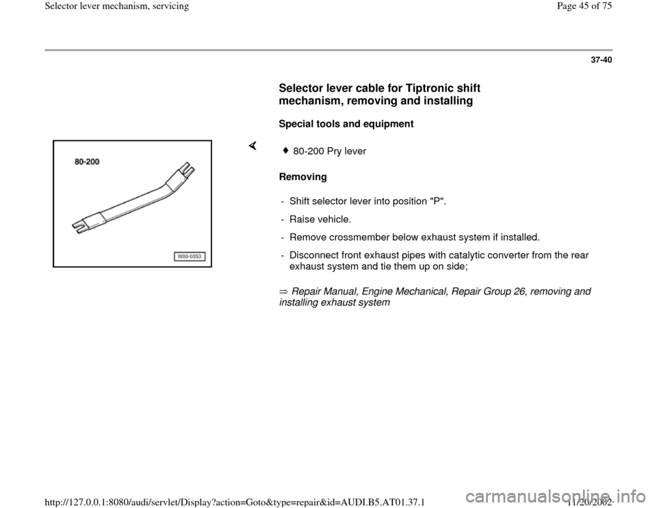
Special tools and equipment
Removing
Repair Manual, Engine Mechanical, Repair Group 26, removing and
installing exhaust system
80-200 Pry lever
- Shift selector lever into position "P".
- Raise vehicle.
- Remove crossmember below exhaust system if installed.
- Disconnect front exhaust pipes with catalytic converter from the rear
exhaust system and tie them up on side;
Pa
ge 45 of 75 Selector lever mechanism, servicin
g
11/20/2002 htt
p://127.0.0.1:8080/audi/servlet/Dis
play?action=Goto&t
yp
e=re
pair&id=AUDI.B5.AT01.37.1
Page 46 of 75
37-41
All-wheel-drive vehicles
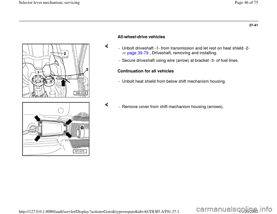
Continuation for all vehicles - Unbolt driveshaft -1- from transmission and let rest on heat shield -2-
page 39
-79
, Driveshaft, removing and installing.
- Secure driveshaft using wire (arrow) at bracket -3- of fuel lines.
- Unbolt heat shield from below shift mechanism housing.
- Remove cover from shift mechanism housing (arrows).
Pa
ge 46 of 75 Selector lever mechanism, servicin
g
11/20/2002 htt
p://127.0.0.1:8080/audi/servlet/Dis
play?action=Goto&t
yp
e=re
pair&id=AUDI.B5.AT01.37.1
Page 47 of 75
37-42
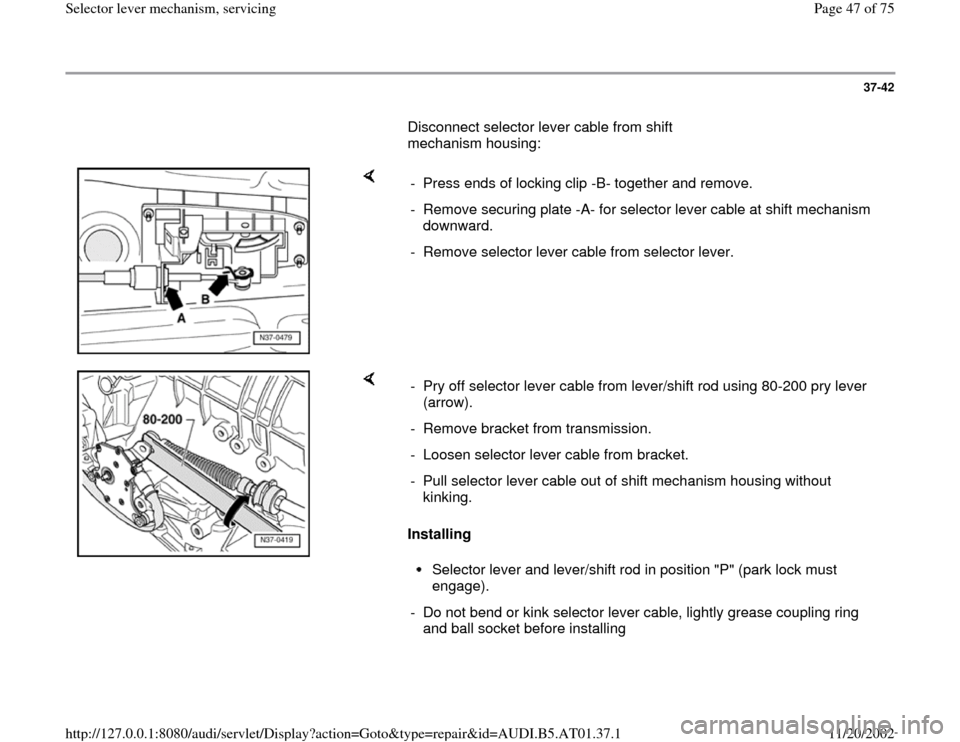
Disconnect selector lever cable from shift
mechanism housing:
- Press ends of locking clip -B- together and remove.
- Remove securing plate -A- for selector lever cable at shift mechanism
downward.
- Remove selector lever cable from selector lever.
Installing - Pry off selector lever cable from lever/shift rod using 80-200 pry lever
(arrow).
- Remove bracket from transmission.
- Loosen selector lever cable from bracket.
- Pull selector lever cable out of shift mechanism housing without
kinking.
Selector lever and lever/shift rod in position "P" (park lock must
engage).
- Do not bend or kink selector lever cable, lightly grease coupling ring
and ball socket before installing
Pa
ge 47 of 75 Selector lever mechanism, servicin
g
11/20/2002 htt
p://127.0.0.1:8080/audi/servlet/Dis
play?action=Goto&t
yp
e=re
pair&id=AUDI.B5.AT01.37.1
Page 48 of 75
37-43
- Guide selector lever cable into shift mechanism
housing.
- Connect selector lever cable to selector lever.
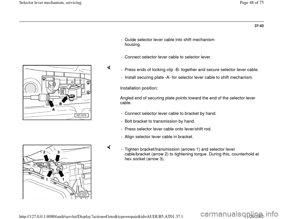
Installation position:
Angled end of securing plate points toward the end of the selector lever
cable. - Press ends of locking clip -B- together and secure selector lever cable.
- Install securing plate -A- for selector lever cable to shift mechanism.
- Connect selector lever cable to bracket by hand.
- Bolt bracket to transmission by hand.
- Press selector lever cable onto lever/shift rod.
- Align selector lever cable in bracket.
- Tighten bracket/transmission (arrows 1) and selector lever
cable/bracket (arrow 2) to tightening torque. During this, counterhold at
hex socket (arrow 3).
Pa
ge 48 of 75 Selector lever mechanism, servicin
g
11/20/2002 htt
p://127.0.0.1:8080/audi/servlet/Dis
play?action=Goto&t
yp
e=re
pair&id=AUDI.B5.AT01.37.1
Page 49 of 75
37-44
All-wheel-drive vehicles
Continuation for all vehicles
Repair Manual, Engine Mechanical, Repair Group 26, removing and
installing exhaust system.
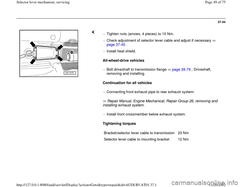
Tightening torques - Tighten nuts (arrows, 4 pieces) to 10 Nm.
- Check adjustment of selector lever cable and adjust if necessary
page 37
-45
.
- Install heat shield.
- Bolt driveshaft to transmission flange page 39
-79
, Driveshaft,
removing and installing.
- Connecting front exhaust pipe to rear exhaust system:- Install front crossmember below exhaust system.
Bracket/selector lever cable to transmission 23 Nm
Selector lever cable to mounting bracket 12 Nm
Pa
ge 49 of 75 Selector lever mechanism, servicin
g
11/20/2002 htt
p://127.0.0.1:8080/audi/servlet/Dis
play?action=Goto&t
yp
e=re
pair&id=AUDI.B5.AT01.37.1
Page 50 of 75
37-45
Selector lever cable for Tiptronic shift
mechanism, checking and adjusting
Checking
- Shift selector lever into position "P".
- Raise vehicle.
- Remove shielding plate/selector lever cable.
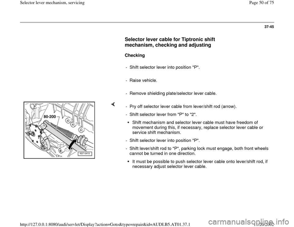
- Pry off selector lever cable from lever/shift rod (arrow).
- Shift selector lever from "P" to "2".
Shift mechanism and selector lever cable must have freedom of
movement during this, if necessary, replace selector lever cable or
service shift mechanism.
- Shift selector lever into position "P".
- Shift lever/shift rod to "P", parking lock must engage, both front wheels
cannot be turned in one direction. It must be possible to push selector lever cable onto lever/shift rod, if
necessary adjust selector lever cable.
Pa
ge 50 of 75 Selector lever mechanism, servicin
g
11/20/2002 htt
p://127.0.0.1:8080/audi/servlet/Dis
play?action=Goto&t
yp
e=re
pair&id=AUDI.B5.AT01.37.1