AUDI A6 1999 C5 / 2.G 01E Transmission Final Drive Pinion Assembly Workshop Manual
A6 1999 C5 / 2.G
AUDI
AUDI
https://www.carmanualsonline.info/img/6/1302/w960_1302-0.png
AUDI A6 1999 C5 / 2.G 01E Transmission Final Drive Pinion Assembly Workshop Manual
Page 3 of 13
39-135
Thrust pad 3062
Drift 3138
Fitting appliance 3253 with 3253/3 and
3253/4
Retainer 3304
Engine/transmission jack V.A.G 1383 A
Universal support V.A.G 1359/2
Separating tool Kukko 17/2
Two-arm puller Kukko 21/7
Counter-support Kukko 22/2
Torque gauge 0-600 Ncm
Socket attachment (long), 32 mm A/F
Pa
ge 3 of 13 Drive
pinion, removin
g, installin
g, disassemblin
g and assemblin
g
11/19/2002 htt
p://127.0.0.1:8080/audi/servlet/Dis
play?action=Goto&t
yp
e=re
pair&id=AUDI.B5.TM03.39.18
Page 4 of 13
39-136
Note:
General repair instructions Page 00
-11
.
Removing drive flange housing from rear final
drive with final drive installed Page 39
-82
.
Removing drive flange housing from rear final
drive with final drive removed Page 39
-111
.
Replace both tapered roller bearings together.
Use same make if possible.
Do not additionally oil new tapered roller
bearings for friction torque measurement. The
bearings have already been treated with a
special oil by the manufacturer.
Removing differential Page 39
-112
.
Adjustments are required when replacing
components marked with a 1) Page 39
-150
,
Adjustment overview
Pa
ge 4 of 13 Drive
pinion, removin
g, installin
g, disassemblin
g and assemblin
g
11/19/2002 htt
p://127.0.0.1:8080/audi/servlet/Dis
play?action=Goto&t
yp
e=re
pair&id=AUDI.B5.TM03.39.18
Page 5 of 13
39-137
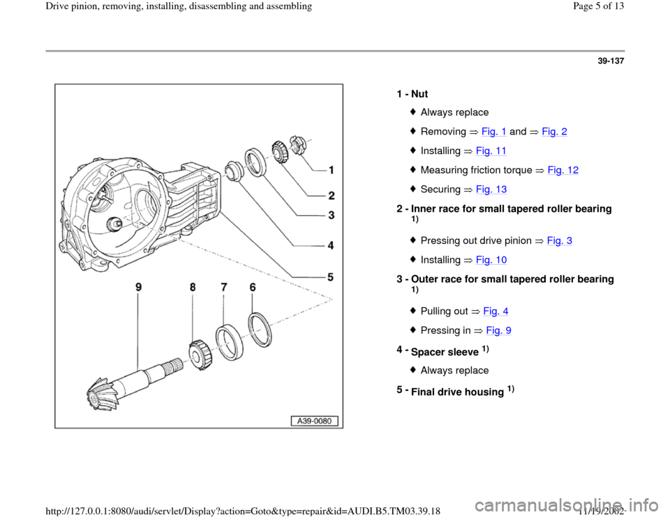
1 -
Nut
Always replaceRemoving Fig. 1
and Fig. 2
Installing Fig. 11Measuring friction torque Fig. 12Securing Fig. 13
2 -
Inner race for small tapered roller bearing
1) Pressing out drive pinion Fig. 3Installing Fig. 10
3 -
Outer race for small tapered roller bearing
1) Pulling out Fig. 4Pressing in Fig. 9
4 -
Spacer sleeve
1)
Always replace
5 -
Final drive housing
1)
Pa
ge 5 of 13 Drive
pinion, removin
g, installin
g, disassemblin
g and assemblin
g
11/19/2002 htt
p://127.0.0.1:8080/audi/servlet/Dis
play?action=Goto&t
yp
e=re
pair&id=AUDI.B5.TM03.39.18
Page 12 of 13
39-144
Note:
If the specified friction torque is exceeded, the spacer sleeve must be
replaced and the adjustment repeated. A spacer sleeve which has been
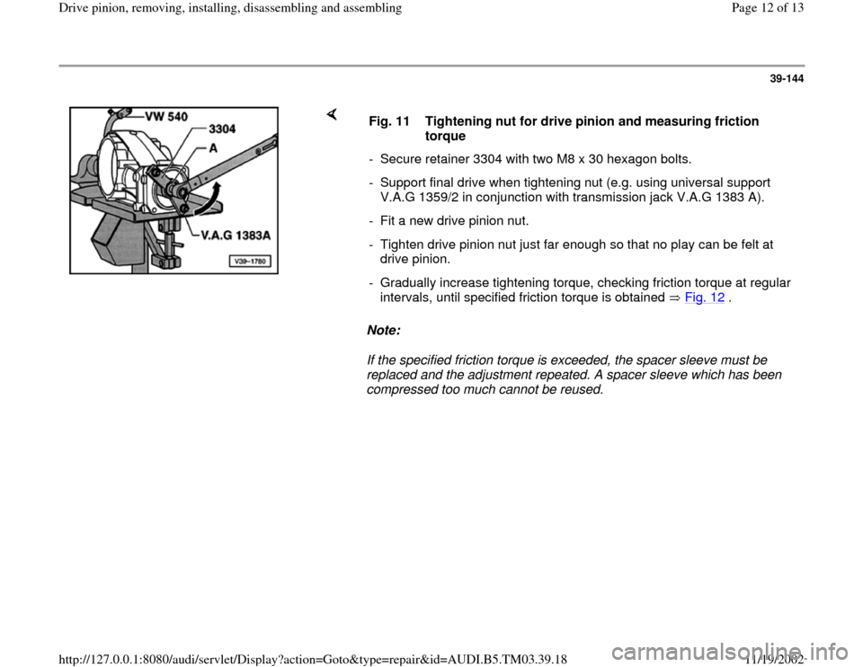
compressed too much cannot be reused. Fig. 11 Tightening nut for drive pinion and measuring friction
torque
- Secure retainer 3304 with two M8 x 30 hexagon bolts.
- Support final drive when tightening nut (e.g. using universal support
V.A.G 1359/2 in conjunction with transmission jack V.A.G 1383 A).
- Fit a new drive pinion nut.
- Tighten drive pinion nut just far enough so that no play can be felt at
drive pinion.
- Gradually increase tightening torque, checking friction torque at regular
intervals, until specified friction torque is obtained Fig. 12
. Pa
ge 12 of 13 Drive
pinion, removin
g, installin
g, disassemblin
g and assemblin
g
11/19/2002 htt
p://127.0.0.1:8080/audi/servlet/Dis
play?action=Goto&t
yp
e=re
pair&id=AUDI.B5.TM03.39.18
Page 13 of 13
39-145
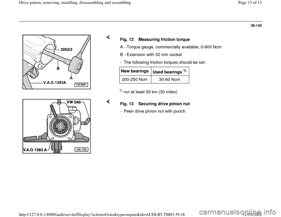
1) run at least 50 km (30 miles) Fig. 12 Measuring friction torque
A - Torque gauge, commercially available, 0-600 Ncm
B - Extension with 32 mm socket
- The following friction torques should be set:New bearings
Used bearings
1)
200-250 Ncm 30-60 Ncm
Fig. 13 Securing drive pinion nut
- Peen drive pinion nut with punch.
Pa
ge 13 of 13 Drive
pinion, removin
g, installin
g, disassemblin
g and assemblin
g
11/19/2002 htt
p://127.0.0.1:8080/audi/servlet/Dis
play?action=Goto&t
yp
e=re
pair&id=AUDI.B5.TM03.39.18
