display AUDI A6 1999 C5 / 2.G 01V Transmission Read Measuring Value Block E18/2 User Guide
[x] Cancel search | Manufacturer: AUDI, Model Year: 1999, Model line: A6, Model: AUDI A6 1999 C5 / 2.GPages: 42, PDF Size: 0.14 MB
Page 15 of 42
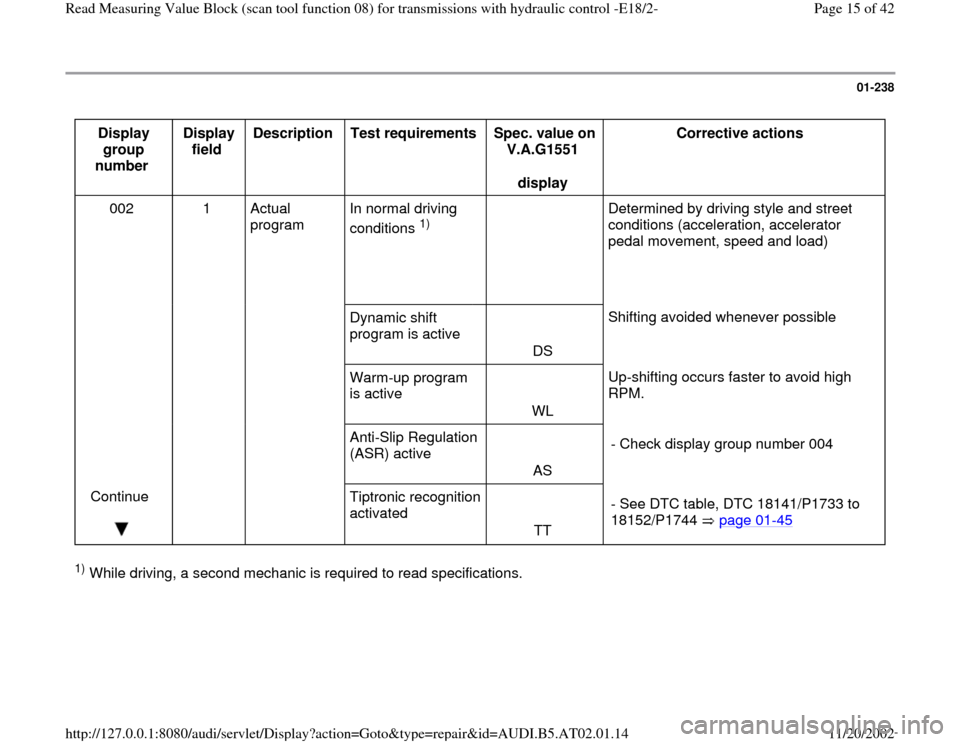
01-238
Display
group
number Display
field Description
Test requirements
Spec. value on
V.A.G1551
display Corrective actions
002 1 Actual
program
In normal driving
conditions
1)
Determined by driving style and street
conditions (acceleration, accelerator
pedal movement, speed and load)
Dynamic shift
program is active
DS Shifting avoided whenever possible
Warm-up program
is active
WL Up-shifting occurs faster to avoid high
RPM.
Anti-Slip Regulation
(ASR) active
AS - Check display group number 004
Continue
Tiptronic recognition
activated
TT - See DTC table, DTC 18141/P1733 to
18152/P1744 page 01
-45
1) While driving, a second mechanic is required to read specifications.
Pa
ge 15 of 42 Read Measurin
g Value Block
(scan tool function 08
) for transmissions with h
ydraulic control -E18/2-
11/20/2002 htt
p://127.0.0.1:8080/audi/servlet/Dis
play?action=Goto&t
yp
e=re
pair&id=AUDI.B5.AT02.01.14
Page 16 of 42
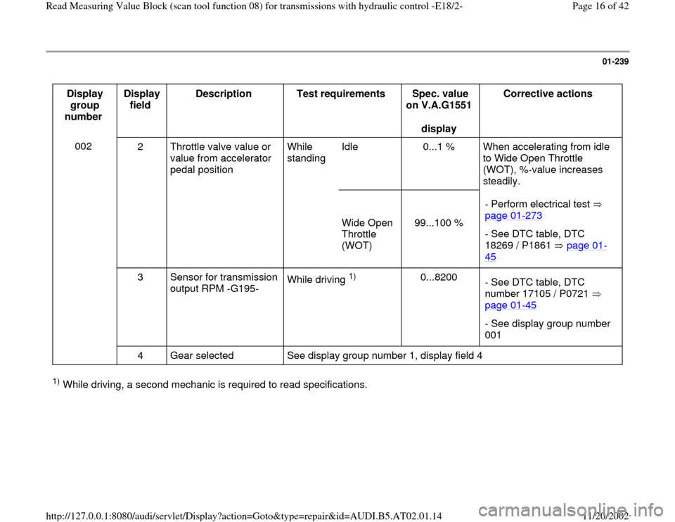
01-239
Display
group
number Display
field Description
Test requirements
Spec. value
on V.A.G1551
display Corrective actions
002
2 Throttle valve value or
value from accelerator
pedal position While
standing Idle 0...1 % When accelerating from idle
to Wide Open Throttle
(WOT), %-value increases
steadily.
Wide Open
Throttle
(WOT)
99...100 % - Perform electrical test
page 01
-273
- See DTC table, DTC
18269 / P1861 page 01
-
45
3 Sensor for transmission
output RPM -G195- While driving
1)
0...8200
- See DTC table, DTC
number 17105 / P0721
page 01
-45
- See display group number
001
4 Gear selected See display group number 1, display field 4
1) While driving, a second mechanic is required to read specifications.
Pa
ge 16 of 42 Read Measurin
g Value Block
(scan tool function 08
) for transmissions with h
ydraulic control -E18/2-
11/20/2002 htt
p://127.0.0.1:8080/audi/servlet/Dis
play?action=Goto&t
yp
e=re
pair&id=AUDI.B5.AT02.01.14
Page 17 of 42
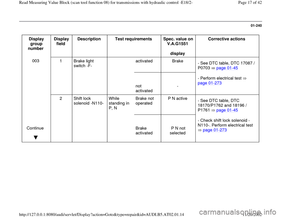
01-240
Display
group
number Display
field Description
Test requirements
Spec. value on
V.A.G1551
display Corrective actions
003
1 Brake light
switch -F- activated Brake
- See DTC table, DTC 17087 /
P0703 page 01
-45
not
activated
- - Perform electrical test
page 01
-273
2 Shift lock
solenoid -N110- While
standing in
P, N Brake not
operated P N active
- See DTC table, DTC
18170/P1762 and 18196 /
P1761 page 01
-45
Continue
Brake
activated
P N not
selected - Check shift lock solenoid -
N110-. Perform electrical test
page 01
-273
Pa
ge 17 of 42 Read Measurin
g Value Block
(scan tool function 08
) for transmissions with h
ydraulic control -E18/2-
11/20/2002 htt
p://127.0.0.1:8080/audi/servlet/Dis
play?action=Goto&t
yp
e=re
pair&id=AUDI.B5.AT02.01.14
Page 18 of 42
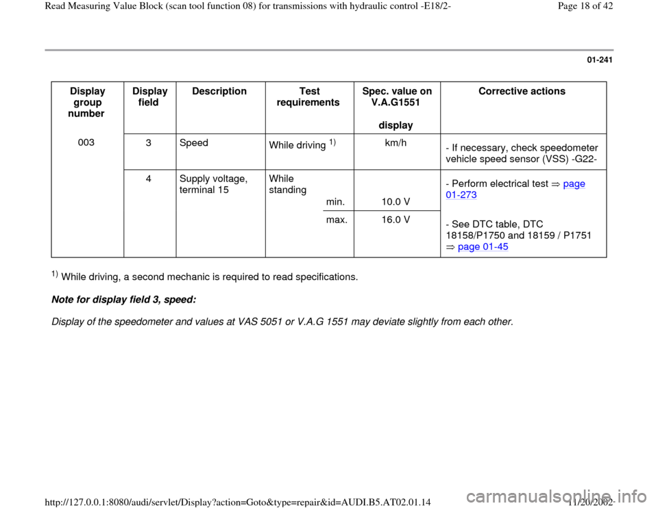
01-241
Display
group
number Display
field Description
Test
requirements Spec. value on
V.A.G1551
display Corrective actions
003
3 Speed
While driving
1)
km/h
- If necessary, check speedometer
vehicle speed sensor (VSS) -G22-
4 Supply voltage,
terminal 15 While
standing
min.
10.0 V - Perform electrical test page
01
-273
max. 16.0 V
- See DTC table, DTC
18158/P1750 and 18159 / P1751
page 01
-45
1) While driving, a second mechanic is required to read specifications.
Note for display field 3, speed:
Display of the speedometer and values at VAS 5051 or V.A.G 1551 may deviate slightly from each other.
Pa
ge 18 of 42 Read Measurin
g Value Block
(scan tool function 08
) for transmissions with h
ydraulic control -E18/2-
11/20/2002 htt
p://127.0.0.1:8080/audi/servlet/Dis
play?action=Goto&t
yp
e=re
pair&id=AUDI.B5.AT02.01.14
Page 19 of 42
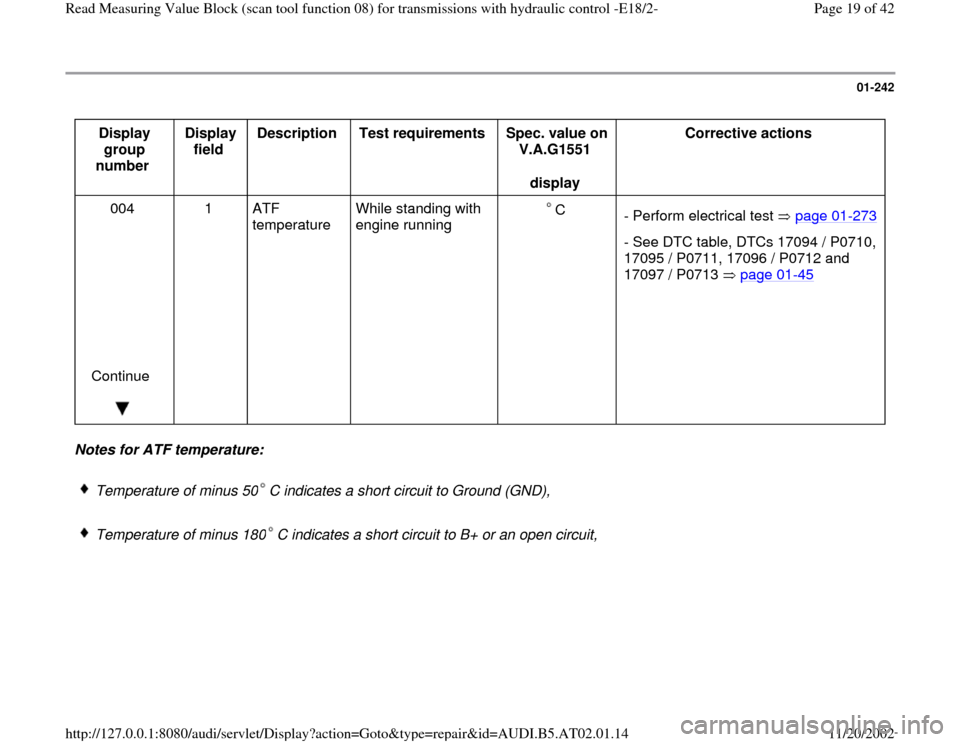
01-242
Display
group
number Display
field Description
Test requirements
Spec. value on
V.A.G1551
display Corrective actions
004
Continue
1 ATF
temperature
While standing with
engine running C
- Perform electrical test page 01
-273
- See DTC table, DTCs 17094 / P0710,
17095 / P0711, 17096 / P0712 and
17097 / P0713 page 01
-45
Notes for ATF temperature:
Temperature of minus 50 C indicates a short circuit to Ground (GND), Temperature of minus 180 C indicates a short circuit to B+ or an open circuit,
Pa
ge 19 of 42 Read Measurin
g Value Block
(scan tool function 08
) for transmissions with h
ydraulic control -E18/2-
11/20/2002 htt
p://127.0.0.1:8080/audi/servlet/Dis
play?action=Goto&t
yp
e=re
pair&id=AUDI.B5.AT02.01.14
Page 20 of 42
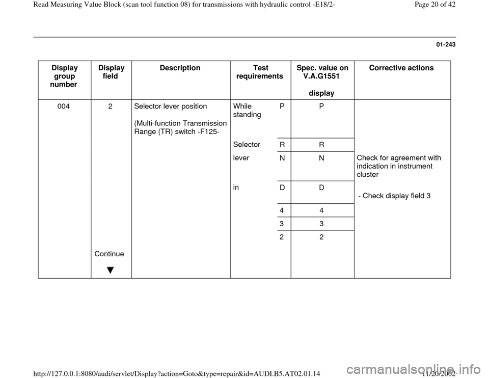
01-243
Display
group
number Display
field Description
Test
requirements Spec. value on
V.A.G1551
display Corrective actions
004 2 Selector lever position
(Multi-function Transmission
Range (TR) switch -F125- While
standing P P
Selector
R R
lever
N N Check for agreement with
indication in instrument
cluster
in
D D
- Check display field 3
4 4
3 3
Continue
2 2
Pa
ge 20 of 42 Read Measurin
g Value Block
(scan tool function 08
) for transmissions with h
ydraulic control -E18/2-
11/20/2002 htt
p://127.0.0.1:8080/audi/servlet/Dis
play?action=Goto&t
yp
e=re
pair&id=AUDI.B5.AT02.01.14
Page 21 of 42
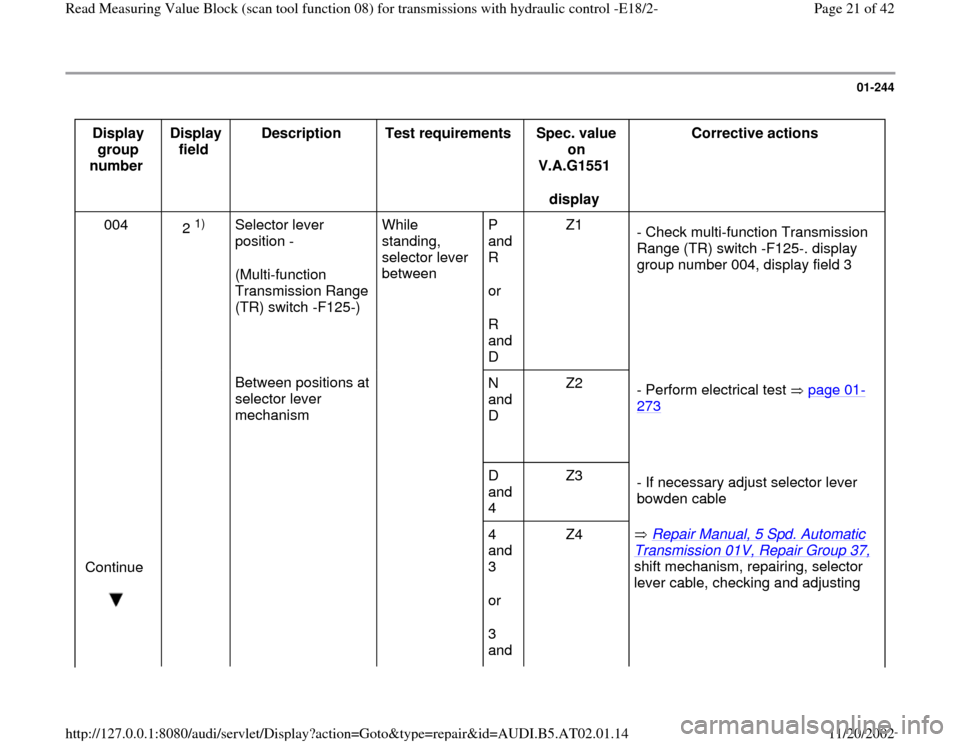
01-244
Display
group
number Display
field Description
Test requirements
Spec. value
on
V.A.G1551
display Corrective actions
004
2
1)
Selector lever
position -
(Multi-function
Transmission Range
(TR) switch -F125-) While
standing,
selector lever
between P
and
R
or
R
and
D Z1
- Check multi-function Transmission
Range (TR) switch -F125-. display
group number 004, display field 3
Between positions at
selector lever
mechanism
N
and
D Z2
- Perform electrical test page 01
-
273
D
and
4 Z3
- If necessary adjust selector lever
bowden cable
Continue
4
and
3
or
3
and Z4 Repair Manual, 5 Spd. Automatic
Transmission 01V, Repair Group 37, shift mechanism, repairing, selector
lever cable, checking and adjusting
Pa
ge 21 of 42 Read Measurin
g Value Block
(scan tool function 08
) for transmissions with h
ydraulic control -E18/2-
11/20/2002 htt
p://127.0.0.1:8080/audi/servlet/Dis
play?action=Goto&t
yp
e=re
pair&id=AUDI.B5.AT02.01.14
Page 22 of 42
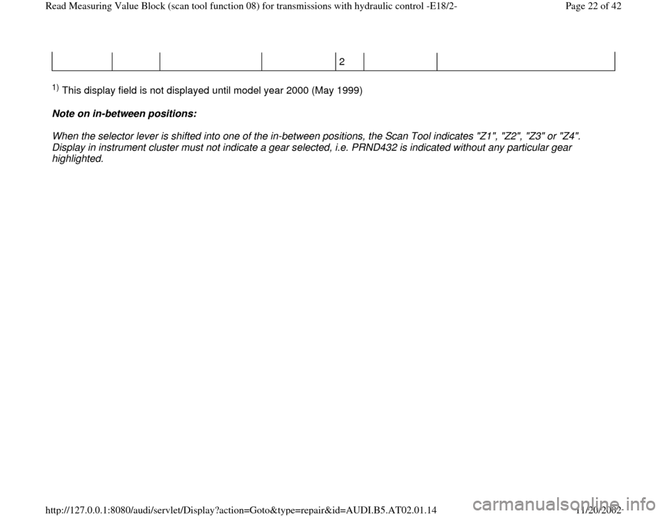
2
1) This display field is not displayed until model year 2000 (May 1999)
Note on in-between positions:
When the selector lever is shifted into one of the in-between positions, the Scan Tool indicates "Z1", "Z2", "Z3" or "Z4".
Display in instrument cluster must not indicate a gear selected, i.e. PRND432 is indicated without any particular gear
highlighted.
Pa
ge 22 of 42 Read Measurin
g Value Block
(scan tool function 08
) for transmissions with h
ydraulic control -E18/2-
11/20/2002 htt
p://127.0.0.1:8080/audi/servlet/Dis
play?action=Goto&t
yp
e=re
pair&id=AUDI.B5.AT02.01.14
Page 23 of 42
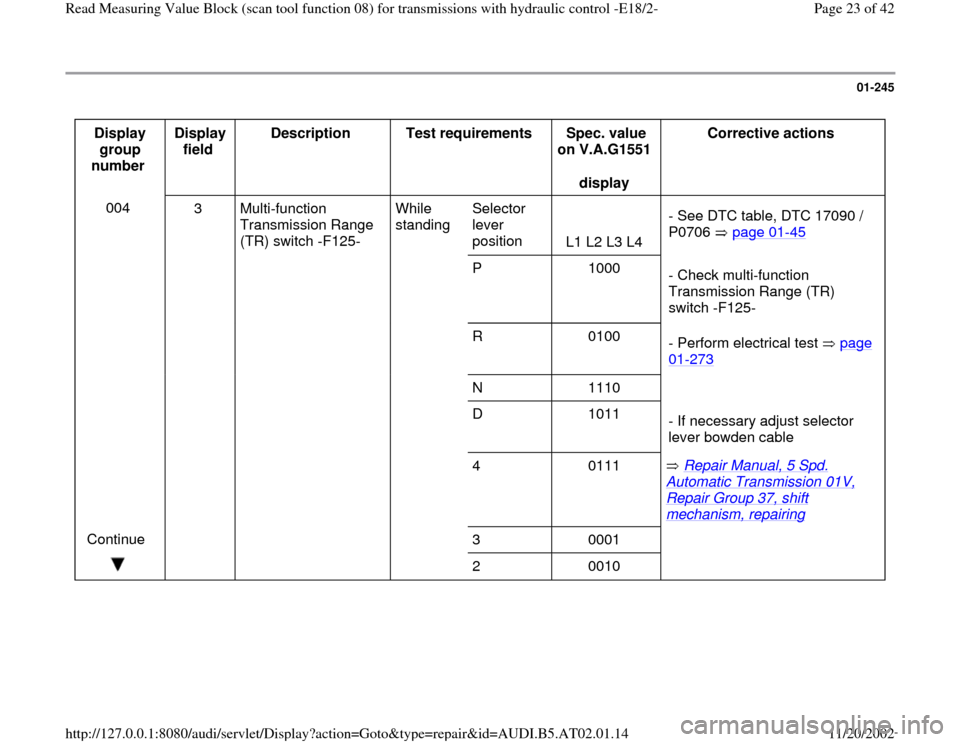
01-245
Display
group
number Display
field Description
Test requirements
Spec. value
on V.A.G1551
display Corrective actions
004
3 Multi-function
Transmission Range
(TR) switch -F125- While
standing Selector
lever
position
L1 L2 L3 L4 - See DTC table, DTC 17090 /
P0706 page 01
-45
P 1000
- Check multi-function
Transmission Range (TR)
switch -F125-
R 0100
- Perform electrical test page
01
-273
N 1110
D 1011
- If necessary adjust selector
lever bowden cable
4 0111 Repair Manual, 5 Spd.
Automatic Transmission 01V, Repair Group 37, shift mechanism, repairing
Continue
3 0001
2 0010
Pa
ge 23 of 42 Read Measurin
g Value Block
(scan tool function 08
) for transmissions with h
ydraulic control -E18/2-
11/20/2002 htt
p://127.0.0.1:8080/audi/servlet/Dis
play?action=Goto&t
yp
e=re
pair&id=AUDI.B5.AT02.01.14
Page 24 of 42
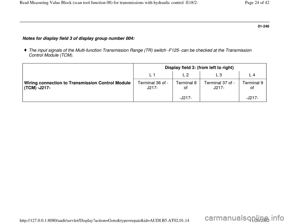
01-246
Notes for display field 3 of display group number 004:
The input signals of the Multi-function Transmission Range (TR) switch -F125- can be checked at the Transmission
Control Module (TCM).
Display field 3: (from left to right)
L 1 L 2 L 3 L 4
Wiring connection to Transmission Control Module
(TCM) -J217- Terminal 36 of -
J217- Terminal 8
of
-J217- Terminal 37 of -
J217- Terminal 9
of
-J217-
Pa
ge 24 of 42 Read Measurin
g Value Block
(scan tool function 08
) for transmissions with h
ydraulic control -E18/2-
11/20/2002 htt
p://127.0.0.1:8080/audi/servlet/Dis
play?action=Goto&t
yp
e=re
pair&id=AUDI.B5.AT02.01.14