AUDI A6 1999 C5 / 2.G ATQ Engine Motronic Injection System Servicing Workshop Manual
Manufacturer: AUDI, Model Year: 1999, Model line: A6, Model: AUDI A6 1999 C5 / 2.GPages: 78, PDF Size: 1 MB
Page 1 of 78
24-1
Motronic injection system,
servicing
Safety precautions
If special testing equipment is required during
road test, note the following:
WARNING!
Scan tools and testing devices must always
be secured on the rear seat and operated
from there by a second person.
If a scan tool or testing device were to be
operated from the passenger seat and there
were an accident involving activation of the
passenger-side airbag, the person seated
there could be seriously injured.
To reduce the risk of personal injury and/or
damage to the fuel injection and ignition system,
always observe the following:
Only disconnect and reconnect wires for
injection and ignition system, including test
leads, when ignition is turned off.
If engine is to be cranked at starting RPM
without starting (e.g. for compression testing),
Pa
ge 1 of 78 Motronic in
jection s
ystem, servicin
g
11/23/2002 htt
p://127.0.0.1:8080/audi/servlet/Dis
play?action=Goto&t
yp
e=re
pair&id=AUDI.B5.FU05.24.1
Page 2 of 78
disconnect connector from ignition coils and
from fuel injectors.
Pa
ge 2 of 78 Motronic in
jection s
ystem, servicin
g
11/23/2002 htt
p://127.0.0.1:8080/audi/servlet/Dis
play?action=Goto&t
yp
e=re
pair&id=AUDI.B5.FU05.24.1
Page 3 of 78
24-2
It is possible that the control module will
recognize a malfunction and store a DTC during
some tests. After completing all tests and
repairs, DTC memory should therefore be
checked and erased if necessary. Readiness
code must be generated after DTC memory is
erased Page 01
-82
.
Always switch ignition off before cleaning
engine.
The battery should only be disconnected and
reconnected when the ignition is turned off,
since otherwise the Engine Control Module
(ECM) can be damaged.
WARNING!
Fuel system is under pressure! Place a cloth
around the connection point before opening
system. Then release pressure by carefully
loosening connection point.
Pa
ge 3 of 78 Motronic in
jection s
ystem, servicin
g
11/23/2002 htt
p://127.0.0.1:8080/audi/servlet/Dis
play?action=Goto&t
yp
e=re
pair&id=AUDI.B5.FU05.24.1
Page 4 of 78
24-3
Rules of cleanliness
When working on the fuel supply or fuel injection
systems, the following "6 rules of cleanliness"
should be carefully observed:
Thoroughly clean all connections and the
surrounding area before disconnecting.
Place parts that have been removed on a clean
surface and cover. Use lint-free cloths only!
Carefully cover opened components or seal
them if repairs are not carried out immediately.
Only install clean components: Only unpack
replacement parts immediately prior to
installation. Do not use parts that have been
stored loose (in tool boxes etc.)
When the system is open: Do not work with
compressed air if it can be avoided. Do not
move vehicle unless absolutely necessary.
Disconnected electrical harness connectors:
Protect from dirt and moisture. Be sure harness
connector is dry before connecting.
Pa
ge 4 of 78 Motronic in
jection s
ystem, servicin
g
11/23/2002 htt
p://127.0.0.1:8080/audi/servlet/Dis
play?action=Goto&t
yp
e=re
pair&id=AUDI.B5.FU05.24.1
Page 5 of 78
24-4
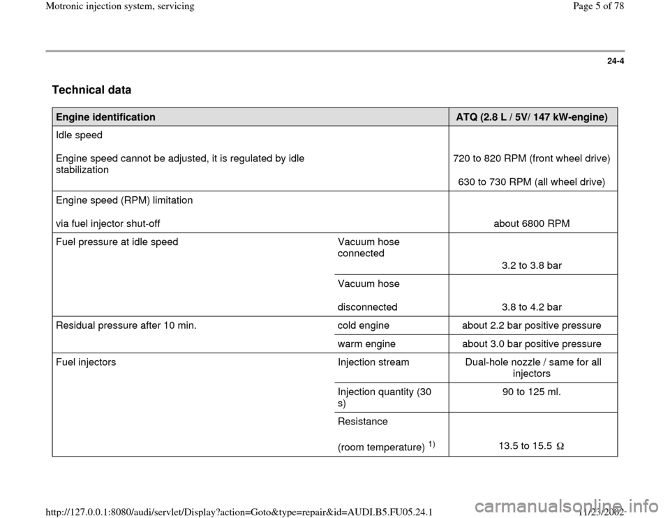
Technical data
Engine identification
ATQ (2.8 L / 5V/ 147 kW-engine)
Idle speed
Engine speed cannot be adjusted, it is regulated by idle
stabilization
720 to 820 RPM (front wheel drive)
630 to 730 RPM (all wheel drive)
Engine speed (RPM) limitation
via fuel injector shut-off
about 6800 RPM
Fuel pressure at idle speed Vacuum hose
connected
3.2 to 3.8 bar
Vacuum hose
disconnected
3.8 to 4.2 bar
Residual pressure after 10 min. cold engine about 2.2 bar positive pressure
warm engine about 3.0 bar positive pressure
Fuel injectors Injection stream Dual-hole nozzle / same for all
injectors
Injection quantity (30
s) 90 to 125 ml.
Resistance
(room temperature)
1)
13.5 to 15.5
Pa
ge 5 of 78 Motronic in
jection s
ystem, servicin
g
11/23/2002 htt
p://127.0.0.1:8080/audi/servlet/Dis
play?action=Goto&t
yp
e=re
pair&id=AUDI.B5.FU05.24.1
Page 6 of 78
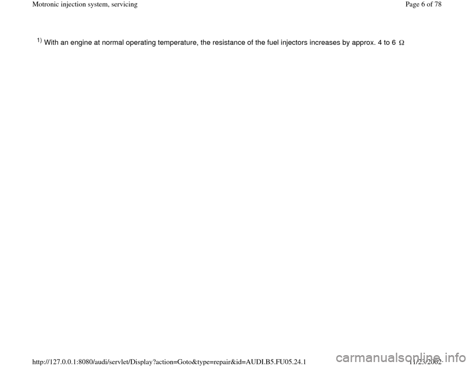
1) With an engine at normal operating temperature, the resistance of the fuel injectors increases by approx. 4 to 6
Pa
ge 6 of 78 Motronic in
jection s
ystem, servicin
g
11/23/2002 htt
p://127.0.0.1:8080/audi/servlet/Dis
play?action=Goto&t
yp
e=re
pair&id=AUDI.B5.FU05.24.1
Page 7 of 78
24-5
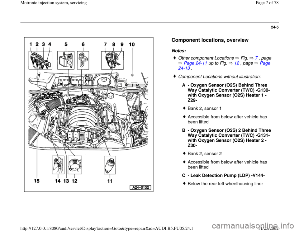
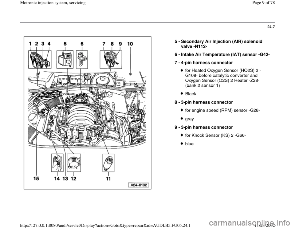
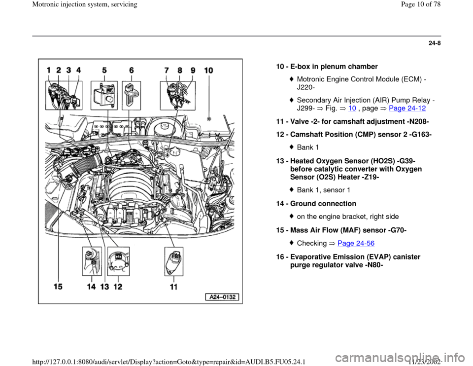
Component locations, overview
Notes:
Other component Locations Fig. 7
, page
Page 24
-11
up to Fig. 12
, page Page
24
-13
.
Component Locations without illustration:
A - Oxygen Sensor (O2S) Behind Three
Way Catalytic Converter (TWC) -G130-
with Oxygen Sensor (O2S) Heater 1 -
Z29-
Bank 2, sensor 1Accessible from below after vehicle has
been lifted
B - Oxygen Sensor (O2S) 2 Behind Three
Way Catalytic Converter (TWC) -G131-
with Oxygen Sensor (O2S) Heater 2 -
Z30- Bank 2, sensor 2Accessible from below after vehicle has
been lifted
C - Leak Detection Pump (LDP) -V144-Below the rear left wheelhousing liner
Pa
ge 7 of 78 Motronic in
jection s
ystem, servicin
g
11/23/2002 htt
p://127.0.0.1:8080/audi/servlet/Dis
play?action=Goto&t
yp
e=re
pair&id=AUDI.B5.FU05.24.1
Page 8 of 78
24-6
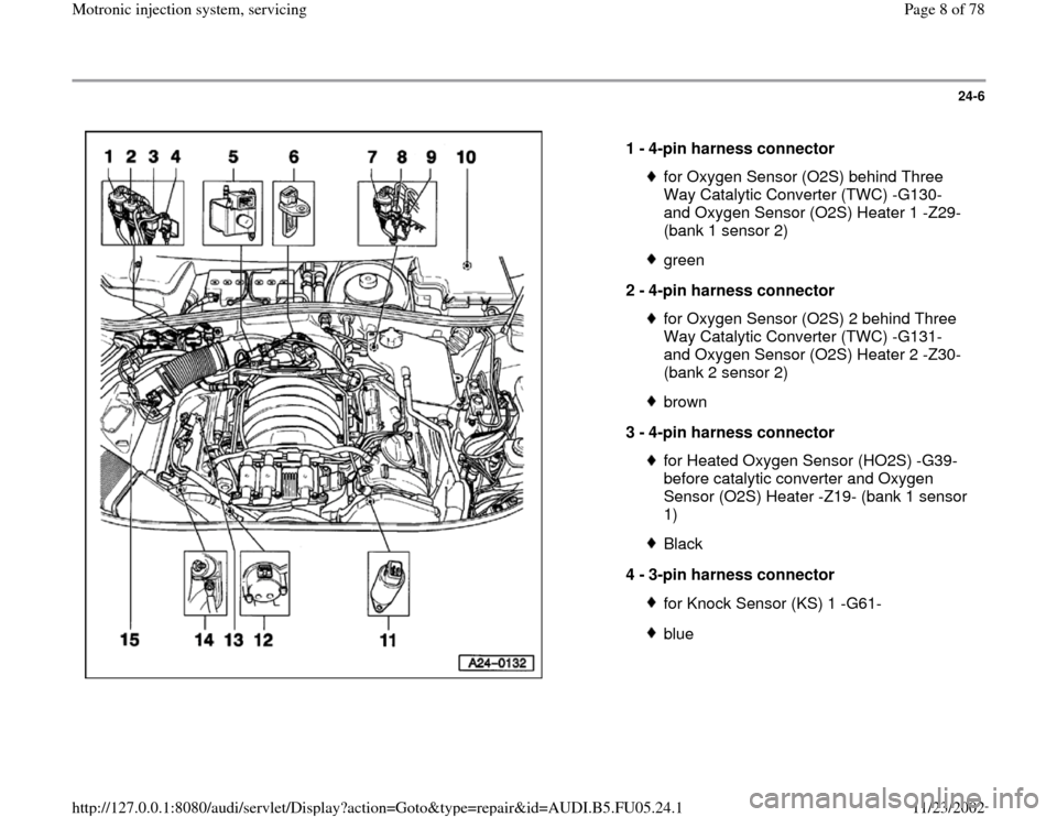
1 -
4-pin harness connector
for Oxygen Sensor (O2S) behind Three
Way Catalytic Converter (TWC) -G130-
and Oxygen Sensor (O2S) Heater 1 -Z29-
(bank 1 sensor 2) green
2 -
4-pin harness connector for Oxygen Sensor (O2S) 2 behind Three
Way Catalytic Converter (TWC) -G131-
and Oxygen Sensor (O2S) Heater 2 -Z30-
(bank 2 sensor 2) brown
3 -
4-pin harness connector for Heated Oxygen Sensor (HO2S) -G39-
before catalytic converter and Oxygen
Sensor (O2S) Heater -Z19- (bank 1 sensor
1) Black
4 -
3-pin harness connector for Knock Sensor (KS) 1 -G61-blue
Pa
ge 8 of 78 Motronic in
jection s
ystem, servicin
g
11/23/2002 htt
p://127.0.0.1:8080/audi/servlet/Dis
play?action=Goto&t
yp
e=re
pair&id=AUDI.B5.FU05.24.1
Page 9 of 78
24-7
5 -
Secondary Air Injection (AIR) solenoid
valve -N112-
6 -
Intake Air Temperature (IAT) sensor -G42-
7 -
4-pin harness connector
for Heated Oxygen Sensor (HO2S) 2 -
G108- before catalytic converter and
Oxygen Sensor (O2S) 2 Heater -Z28-
(bank 2 sensor 1) Black
8 -
3-pin harness connector for engine speed (RPM) sensor -G28-gray
9 -
3-pin harness connector for Knock Sensor (KS) 2 -G66-blue
Pa
ge 9 of 78 Motronic in
jection s
ystem, servicin
g
11/23/2002 htt
p://127.0.0.1:8080/audi/servlet/Dis
play?action=Goto&t
yp
e=re
pair&id=AUDI.B5.FU05.24.1
Page 10 of 78
24-8
10 -
E-box in plenum chamber
Motronic Engine Control Module (ECM) -
J220- Secondary Air Injection (AIR) Pump Relay -
J299- Fig. 10
, page Page 24
-12
11 -
Valve -2- for camshaft adjustment -N208-
12 -
Camshaft Position (CMP) sensor 2 -G163-
Bank 1
13 -
Heated Oxygen Sensor (HO2S) -G39-
before catalytic converter with Oxygen
Sensor (O2S) Heater -Z19- Bank 1, sensor 1
14 -
Ground connection on the engine bracket, right side
15 -
Mass Air Flow (MAF) sensor -G70- Checking Page 24
-56
16 -
Evaporative Emission (EVAP) canister
purge regulator valve -N80-
Pa
ge 10 of 78 Motronic in
jection s
ystem, servicin
g
11/23/2002 htt
p://127.0.0.1:8080/audi/servlet/Dis
play?action=Goto&t
yp
e=re
pair&id=AUDI.B5.FU05.24.1