AUDI A6 2000 C5 / 2.G 01E Transmission Clutch Mechanism Service Workshop Manual
Manufacturer: AUDI, Model Year: 2000,
Model line: A6,
Model: AUDI A6 2000 C5 / 2.G
Pages: 27, PDF Size: 0.6 MB
AUDI A6 2000 C5 / 2.G 01E Transmission Clutch Mechanism Service Workshop Manual
A6 2000 C5 / 2.G
AUDI
AUDI
https://www.carmanualsonline.info/img/6/1287/w960_1287-0.png
AUDI A6 2000 C5 / 2.G 01E Transmission Clutch Mechanism Service Workshop Manual
Trending: auxiliary battery, ignition, brake fluid, battery, air bleeding, engine, light
Page 1 of 27
30-1
Clutch mechanism, servicing
Note:
For vehicles with coded radio, obtain and note
the radio code.
Disconnect battery Ground strap with the
ignition switched off.
Lubricate all bearings and contact surfaces with
G 052 142 A 2 polycarbamide grease.
Before working on pedal cluster, remove cover
below dash panel:
Repair Manual, Body Interior, Repair Group
68
Make sure that no brake fluid escapes into the
footwell, the plenum chamber or onto the
transmission below. If this does happen, clean
the affected areas thoroughly.
When performing work in the footwell, put
cloths on the carpet to protect it from possible
brake fluid spills.
Pa
ge 1 of 27 Clutch mechanism, servicin
g
11/19/2002 htt
p://127.0.0.1:8080/audi/servlet/Dis
play?action=Goto&t
yp
e=re
pair&id=AUDI.B5.TM03.30.1
Page 2 of 27
30-2
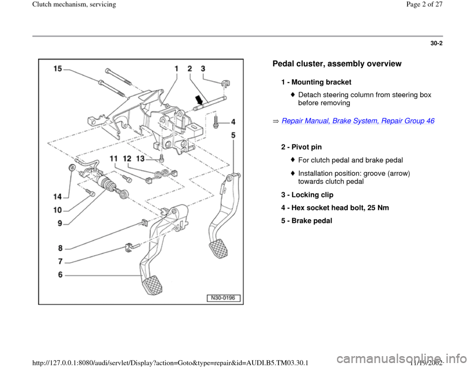
Pedal cluster, assembly overview
Repair Manual, Brake System, Repair Group 46
1 -
Mounting bracket
Detach steering column from steering box
before removing
2 -
Pivot pin
For clutch pedal and brake pedalInstallation position: groove (arrow)
towards clutch pedal
3 -
Locking clip
4 -
Hex socket head bolt, 25 Nm
5 -
Brake pedal
Pa
ge 2 of 27 Clutch mechanism, servicin
g
11/19/2002 htt
p://127.0.0.1:8080/audi/servlet/Dis
play?action=Goto&t
yp
e=re
pair&id=AUDI.B5.TM03.30.1
Page 3 of 27
30-3
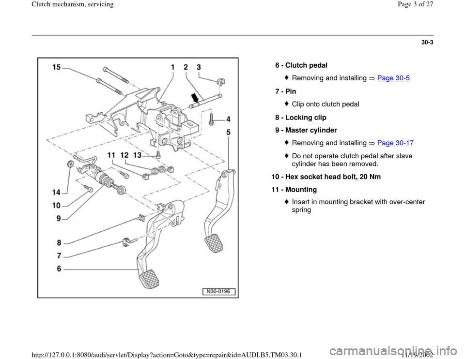
6 -
Clutch pedal
Removing and installing Page 30
-5
7 -
Pin
Clip onto clutch pedal
8 -
Locking clip
9 -
Master cylinder Removing and installing Page 30
-17
Do not operate clutch pedal after slave
cylinder has been removed.
10 -
Hex socket head bolt, 20 Nm
11 -
Mounting Insert in mounting bracket with over-center
spring
Pa
ge 3 of 27 Clutch mechanism, servicin
g
11/19/2002 htt
p://127.0.0.1:8080/audi/servlet/Dis
play?action=Goto&t
yp
e=re
pair&id=AUDI.B5.TM03.30.1
Page 4 of 27
30-4
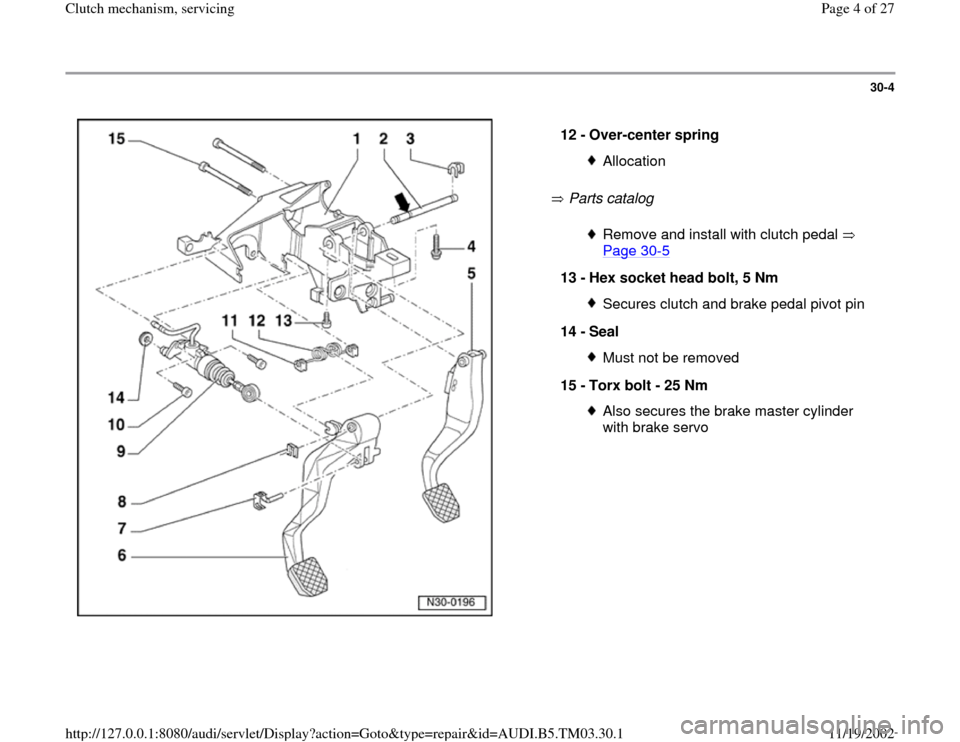
Parts catalog 12 -
Over-center spring
AllocationRemove and install with clutch pedal
Page 30
-5
13 -
Hex socket head bolt, 5 Nm
Secures clutch and brake pedal pivot pin
14 -
Seal Must not be removed
15 -
Torx bolt - 25 Nm Also secures the brake master cylinder
with brake servo
Pa
ge 4 of 27 Clutch mechanism, servicin
g
11/19/2002 htt
p://127.0.0.1:8080/audi/servlet/Dis
play?action=Goto&t
yp
e=re
pair&id=AUDI.B5.TM03.30.1
Page 5 of 27
30-5
Clutch pedal and over-center spring,
removing and installing
Removing
- Remove driver's side storage compartment:
Repair Manual, Body Interior, Repair Group
68
Note:
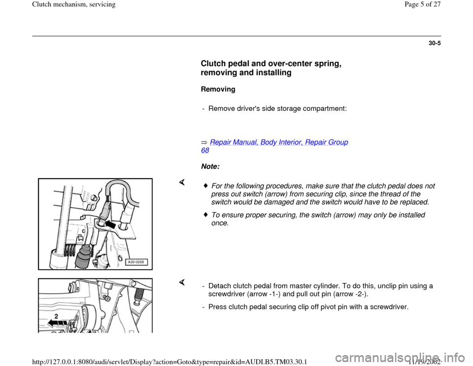
For the following procedures, make sure that the clutch pedal does not
press out switch (arrow) from securing clip, since the thread of the
switch would be damaged and the switch would have to be replaced. To ensure proper securing, the switch (arrow) may only be installed
once.
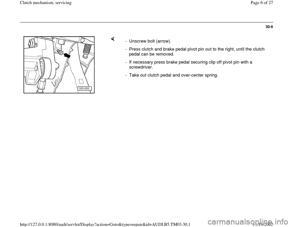
- Detach clutch pedal from master cylinder. To do this, unclip pin using a
screwdriver (arrow -1-) and pull out pin (arrow -2-).
- Press clutch pedal securing clip off pivot pin with a screwdriver.
Pa
ge 5 of 27 Clutch mechanism, servicin
g
11/19/2002 htt
p://127.0.0.1:8080/audi/servlet/Dis
play?action=Goto&t
yp
e=re
pair&id=AUDI.B5.TM03.30.1
Page 6 of 27
30-6
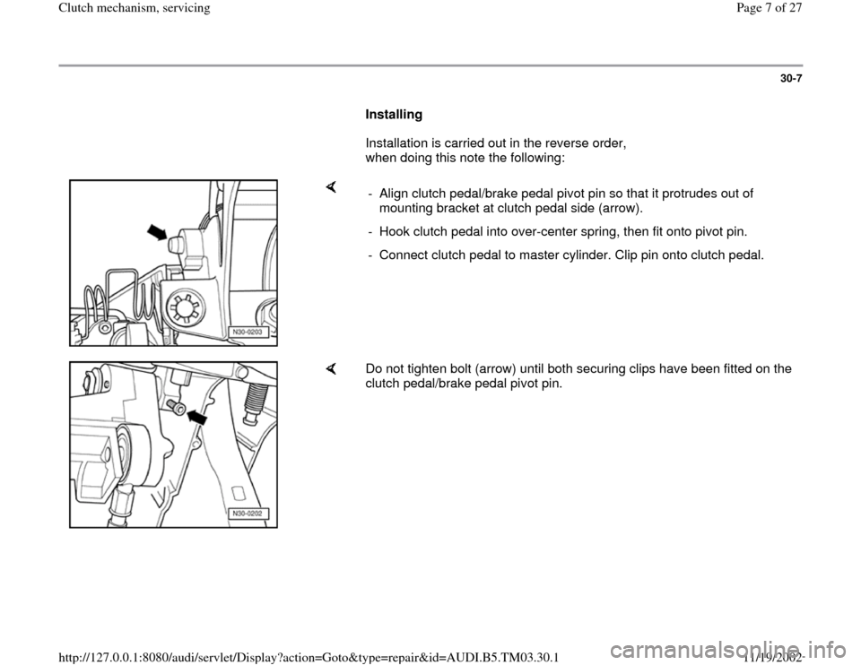
- Unscrew bolt (arrow).
- Press clutch and brake pedal pivot pin out to the right, until the clutch
pedal can be removed.
- If necessary press brake pedal securing clip off pivot pin with a
screwdriver.
- Take out clutch pedal and over-center spring.
Pa
ge 6 of 27 Clutch mechanism, servicin
g
11/19/2002 htt
p://127.0.0.1:8080/audi/servlet/Dis
play?action=Goto&t
yp
e=re
pair&id=AUDI.B5.TM03.30.1
Page 7 of 27
30-7
Installing
Installation is carried out in the reverse order,
when doing this note the following:
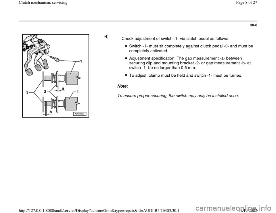
- Align clutch pedal/brake pedal pivot pin so that it protrudes out of
mounting bracket at clutch pedal side (arrow).
- Hook clutch pedal into over-center spring, then fit onto pivot pin.
- Connect clutch pedal to master cylinder. Clip pin onto clutch pedal.
Do not tighten bolt (arrow) until both securing clips have been fitted on the
clutch pedal/brake pedal pivot pin.
Pa
ge 7 of 27 Clutch mechanism, servicin
g
11/19/2002 htt
p://127.0.0.1:8080/audi/servlet/Dis
play?action=Goto&t
yp
e=re
pair&id=AUDI.B5.TM03.30.1
Page 8 of 27
30-8
Note:
To ensure proper securing, the switch may only be installed once. - Check adjustment of switch -1- via clutch pedal as follows:
Switch -1- must sit completely against clutch pedal -3- and must be
completely activated.
Adjustment specification: The gap measurement -a- between
securing clip and mounting bracket -2- or gap measurement -b- at
switch -1- be no larger than 0.5 mm.
To adjust, clamp must be held and switch -1- must be turned.
Pa
ge 8 of 27 Clutch mechanism, servicin
g
11/19/2002 htt
p://127.0.0.1:8080/audi/servlet/Dis
play?action=Goto&t
yp
e=re
pair&id=AUDI.B5.TM03.30.1
Page 9 of 27
30-9
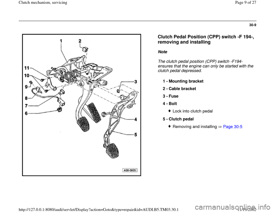
Clutch Pedal Position (CPP) switch -F 194-,
removing and installing
Note
The clutch pedal position (CPP) switch -F194-
ensures that the engine can only be started with the
clutch pedal depressed.
1 -
Mounting bracket
2 -
Cable bracket
3 -
Fuse
4 -
Bolt
Lock into clutch pedal
5 -
Clutch pedal Removing and installing Page 30
-5
Pa
ge 9 of 27 Clutch mechanism, servicin
g
11/19/2002 htt
p://127.0.0.1:8080/audi/servlet/Dis
play?action=Goto&t
yp
e=re
pair&id=AUDI.B5.TM03.30.1
Page 10 of 27
30-10
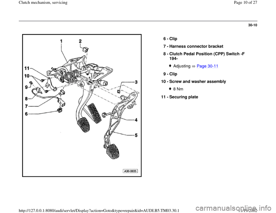
6 -
Clip
7 -
Harness connector bracket
8 -
Clutch Pedal Position (CPP) Switch -F
194-
Adjusting Page 30
-11
9 -
Clip
10 -
Screw and washer assembly
8 Nm
11 -
Securing plate
Pa
ge 10 of 27 Clutch mechanism, servicin
g
11/19/2002 htt
p://127.0.0.1:8080/audi/servlet/Dis
play?action=Goto&t
yp
e=re
pair&id=AUDI.B5.TM03.30.1
Trending: steering, engine, lock, ignition, brake fluid, wiring, battery
