ECU AUDI A6 2000 C5 / 2.G 01E Transmission Remove And Install Workshop Manual
[x] Cancel search | Manufacturer: AUDI, Model Year: 2000, Model line: A6, Model: AUDI A6 2000 C5 / 2.GPages: 21, PDF Size: 0.62 MB
Page 5 of 21

34-22
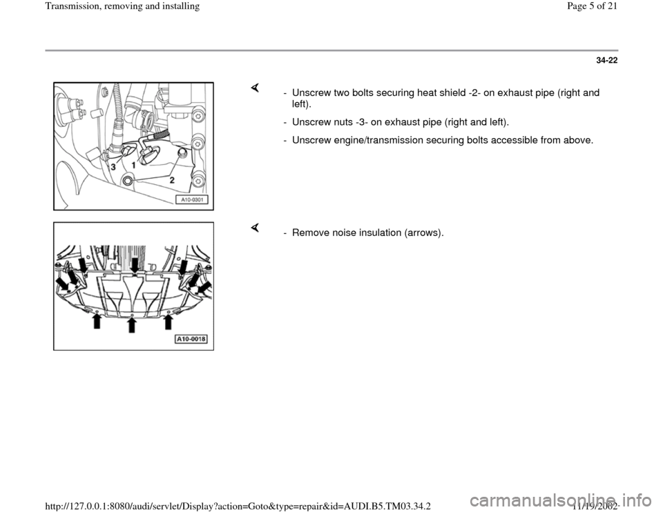
- Unscrew two bolts securing heat shield -2- on exhaust pipe (right and
left).
- Unscrew nuts -3- on exhaust pipe (right and left).
- Unscrew engine/transmission securing bolts accessible from above.
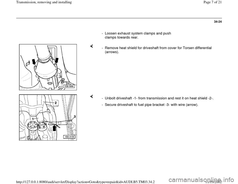
- Remove noise insulation (arrows).
Pa
ge 5 of 21 Transmission, removin
g and installin
g
11/19/2002 htt
p://127.0.0.1:8080/audi/servlet/Dis
play?action=Goto&t
yp
e=re
pair&id=AUDI.B5.TM03.34.2
Page 7 of 21

34-24
- Loosen exhaust system clamps and push
clamps towards rear.
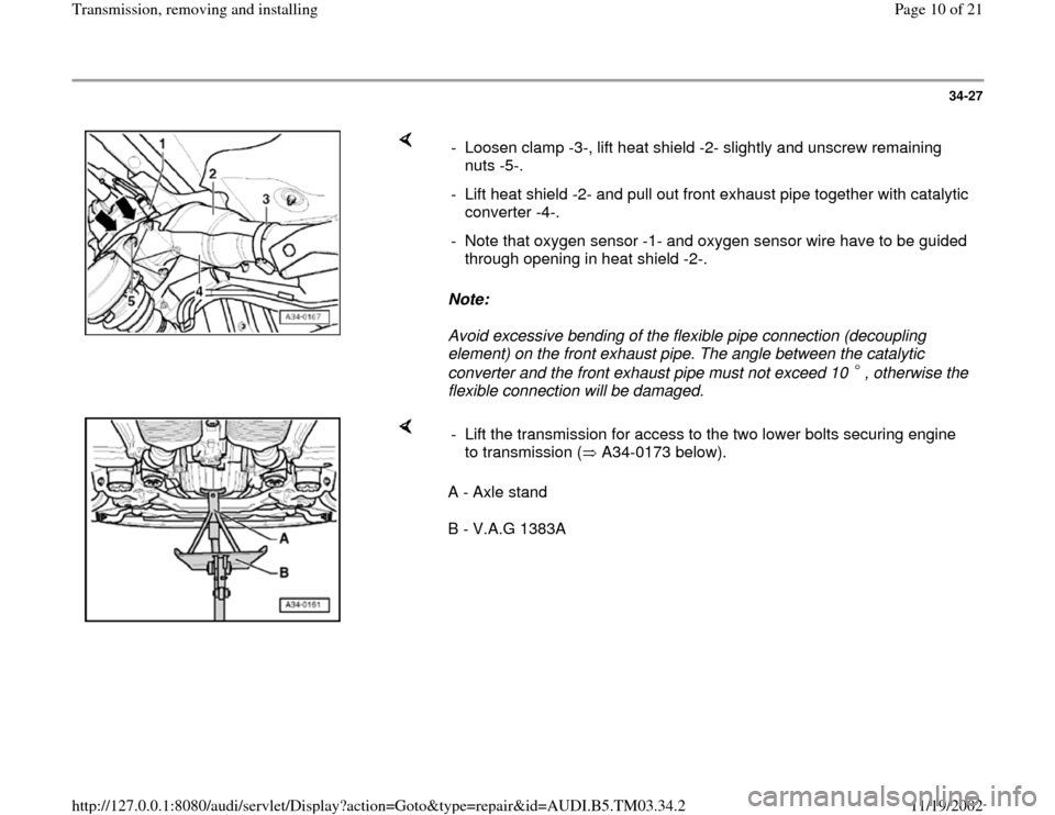
- Remove heat shield for driveshaft from cover for Torsen differential
(arrows).
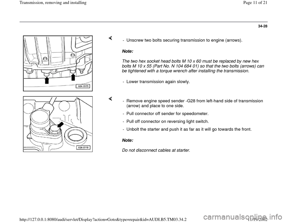
- Unbolt driveshaft -1- from transmission and rest it on heat shield -2-.
- Secure driveshaft to fuel pipe bracket -3- with wire (arrow).
Pa
ge 7 of 21 Transmission, removin
g and installin
g
11/19/2002 htt
p://127.0.0.1:8080/audi/servlet/Dis
play?action=Goto&t
yp
e=re
pair&id=AUDI.B5.TM03.34.2
Page 10 of 21

34-27
Note:
Avoid excessive bending of the flexible pipe connection (decoupling
element) on the front exhaust pipe. The angle between the catalytic
converter and the front exhaust pipe must not exceed 10 , otherwise the
flexible connection will be damaged. - Loosen clamp -3-, lift heat shield -2- slightly and unscrew remaining
nuts -5-.
- Lift heat shield -2- and pull out front exhaust pipe together with catalytic
converter -4-.
- Note that oxygen sensor -1- and oxygen sensor wire have to be guided
through opening in heat shield -2-.
A - Axle stand
B - V.A.G 1383A - Lift the transmission for access to the two lower bolts securing engine
to transmission ( A34-0173 below).
Pa
ge 10 of 21 Transmission, removin
g and installin
g
11/19/2002 htt
p://127.0.0.1:8080/audi/servlet/Dis
play?action=Goto&t
yp
e=re
pair&id=AUDI.B5.TM03.34.2
Page 11 of 21

34-28
Note:
The two hex socket head bolts M 10 x 60 must be replaced by new hex
bolts M 10 x 55 (Part No. N 104 684 01) so that the two bolts (arrows) can
be tightened with a torque wrench after installing the transmission. - Unscrew two bolts securing transmission to engine (arrows).
- Lower transmission again slowly.
Note:
Do not disconnect cables at starter. - Remove engine speed sender -G28 from left-hand side of transmission
(arrow) and place to one side.
- Pull connector off sender for speedometer.
- Pull off connector on reversing light switch.
- Unbolt the starter and push it as far as it will go towards the front.
Pa
ge 11 of 21 Transmission, removin
g and installin
g
11/19/2002 htt
p://127.0.0.1:8080/audi/servlet/Dis
play?action=Goto&t
yp
e=re
pair&id=AUDI.B5.TM03.34.2
Page 14 of 21

34-31
- Remove all but one of the engine/transmission
securing bolts from below (one bolt is left in
place to hold engine and transmission together).
Note:
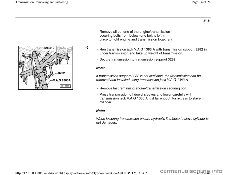
If transmission support 3282 is not available, the transmission can be
removed and installed using transmission jack V.A.G 1383 A.
Note:
When lowering transmission ensure hydraulic line/hose to slave cylinder is
not damaged. - Run transmission jack V.A.G 1383 A with transmission support 3282 in
under transmission and take up weight of transmission.
- Secure transmission to transmission support 3282.
- Remove last remaining engine/transmission securing bolt.
- Press transmission off dowel sleeves and lower carefully with
transmission jack V.A.G 1383 A just far enough for access to slave
cylinder.
Pa
ge 14 of 21 Transmission, removin
g and installin
g
11/19/2002 htt
p://127.0.0.1:8080/audi/servlet/Dis
play?action=Goto&t
yp
e=re
pair&id=AUDI.B5.TM03.34.2