AUDI A6 2000 C5 / 2.G ATW Engine On Board Diagnostic Workshop Manual
Manufacturer: AUDI, Model Year: 2000,
Model line: A6,
Model: AUDI A6 2000 C5 / 2.G
Pages: 19, PDF Size: 0.1 MB
AUDI A6 2000 C5 / 2.G ATW Engine On Board Diagnostic Workshop Manual
A6 2000 C5 / 2.G
AUDI
AUDI
https://www.carmanualsonline.info/img/6/1079/w960_1079-0.png
AUDI A6 2000 C5 / 2.G ATW Engine On Board Diagnostic Workshop Manual
Trending: check engine, fuse diagram, OBD port, warning, check engine light, cruise control, battery
Page 1 of 19
01-1
On Board Diagnostic (OBD)
On Board Diagnostic (OBD), technical
data
Equipment
Data is transmitted between the control module
and the VAS5051 tester or VAG1551 Scan Tool
(ST) via operating mode "Rapid Data Transfer".
DTC memory is designed for permanent
memory and is therefore not dependent on
voltage supply.
Display of stored DTCs occurs after initiation of
display mode Page 01
-16
.
DTC memory must be erased after malfunction
is repaired Page 01
-16
.
Important:
Readiness code must be re-generated after
every time DTC memory is erased Page 01
-
73
.
Pa
ge 1 of 19 On Board Dia
gnostic
(OBD
)
11/21/2002 htt
p://127.0.0.1:8080/audi/servlet/Dis
play?action=Goto&t
yp
e=re
pair&id=AUDI.B5.FU06.01.1
Page 2 of 19
01-2
If the ECM recognizes malfunctions that lead to
a worsening of emissions values, it indicates
them by lighting the Malfunction Indicator Lamp
(MIL) -K83- in the instrument cluster. Meaning
of Malfunction Indicator Lamp (MIL) -K83-
Page 01
-3 .
"E-Gas"-relevant malfunctions are also
indicated by the warning lamp for Electronic
Power Control ("EPC warning lamp").
Pa
ge 2 of 19 On Board Dia
gnostic
(OBD
)
11/21/2002 htt
p://127.0.0.1:8080/audi/servlet/Dis
play?action=Goto&t
yp
e=re
pair&id=AUDI.B5.FU06.01.1
Page 3 of 19
01-3
Malfunction Indicator Lamp (MIL),
significance
If the ECM recognizes malfunctions that lead to a
worsening of emissions values, it indicates them
by lighting the Malfunction Indicator Lamp (MIL).
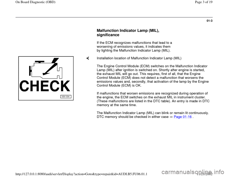
Installation location of Malfunction Indicator Lamp (MIL)
The Engine Control Module (ECM) switches on the Malfunction Indicator
Lamp (MIL) after ignition is switched on. Shortly after engine is started,
the exhaust MIL will go out. This requires, first of all, that the Engine
Control Module (ECM) does not detect a malfunction that worsens the
emissions values and, secondly, that activation of the lamp by the Engine
Control Module (ECM) is OK.
If malfunctions that worsen emissions are recognized during operation of
the engine, the ECM switches on the exhaust MIL in instrument cluster.
(These malfunctions are listed in the DTC table). An entry is made in DTC
memory at the same time.
The Malfunction Indicator Lamp (MIL) can blink or remain lit continuously.
DTC memory should be checked in either case Page 01
-16
.
Pa
ge 3 of 19 On Board Dia
gnostic
(OBD
)
11/21/2002 htt
p://127.0.0.1:8080/audi/servlet/Dis
play?action=Goto&t
yp
e=re
pair&id=AUDI.B5.FU06.01.1
Page 4 of 19
01-4
Continuously lit:
There is a malfunction that causes increased
emissions. Check DTC memory for Motronic
ECM and automatic transmission (if installed).
Check DTC memory if there is a driveability
problem or a customer complaint, but the
Malfunction Indicator Lamp (MIL) is not lit. There
may be DTCs stored that do not cause the
exhaust MIL to light up immediately, but only
after engine is started again and malfunction is
recognized again.
Blinking:
There is a malfunction that causes damage to
the catalytic converter in this driving condition
(e.g. combustion misfire). In this case, vehicle
must only be driven at reduced power!
Note:
Catalytic converter must be checked after
malfunction is repaired.
Pa
ge 4 of 19 On Board Dia
gnostic
(OBD
)
11/21/2002 htt
p://127.0.0.1:8080/audi/servlet/Dis
play?action=Goto&t
yp
e=re
pair&id=AUDI.B5.FU06.01.1
Page 5 of 19
01-5
Malfunction Indicator Lamp (MIL),
checking
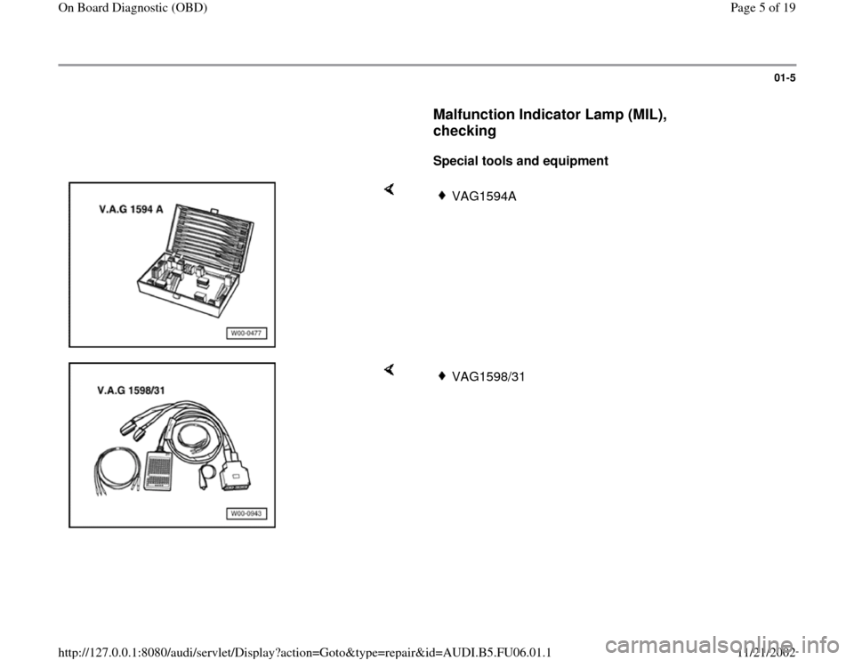
Special tools and equipment
VAG1594A
VAG1598/31
Pa
ge 5 of 19 On Board Dia
gnostic
(OBD
)
11/21/2002 htt
p://127.0.0.1:8080/audi/servlet/Dis
play?action=Goto&t
yp
e=re
pair&id=AUDI.B5.FU06.01.1
Page 6 of 19
01-6
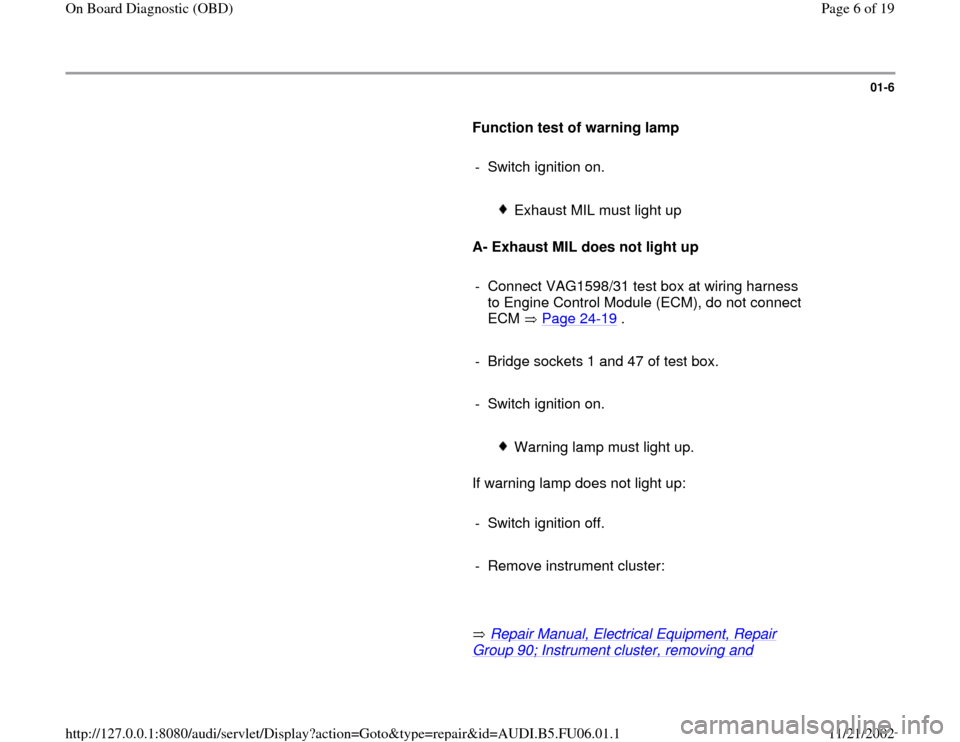
Function test of warning lamp
- Switch ignition on.
Exhaust MIL must light up
A- Exhaust MIL does not light up
- Connect VAG1598/31 test box at wiring harness
to Engine Control Module (ECM), do not connect
ECM Page 24
-19
.
- Bridge sockets 1 and 47 of test box.
- Switch ignition on.
Warning lamp must light up.
If warning lamp does not light up:
- Switch ignition off.
- Remove instrument cluster:
Repair Manual, Electrical Equipment, Repair
Group 90; Instrument cluster, removing and
Pa
ge 6 of 19 On Board Dia
gnostic
(OBD
)
11/21/2002 htt
p://127.0.0.1:8080/audi/servlet/Dis
play?action=Goto&t
yp
e=re
pair&id=AUDI.B5.FU06.01.1
Page 7 of 19
installing
Pa
ge 7 of 19 On Board Dia
gnostic
(OBD
)
11/21/2002 htt
p://127.0.0.1:8080/audi/servlet/Dis
play?action=Goto&t
yp
e=re
pair&id=AUDI.B5.FU06.01.1
Page 8 of 19
01-7
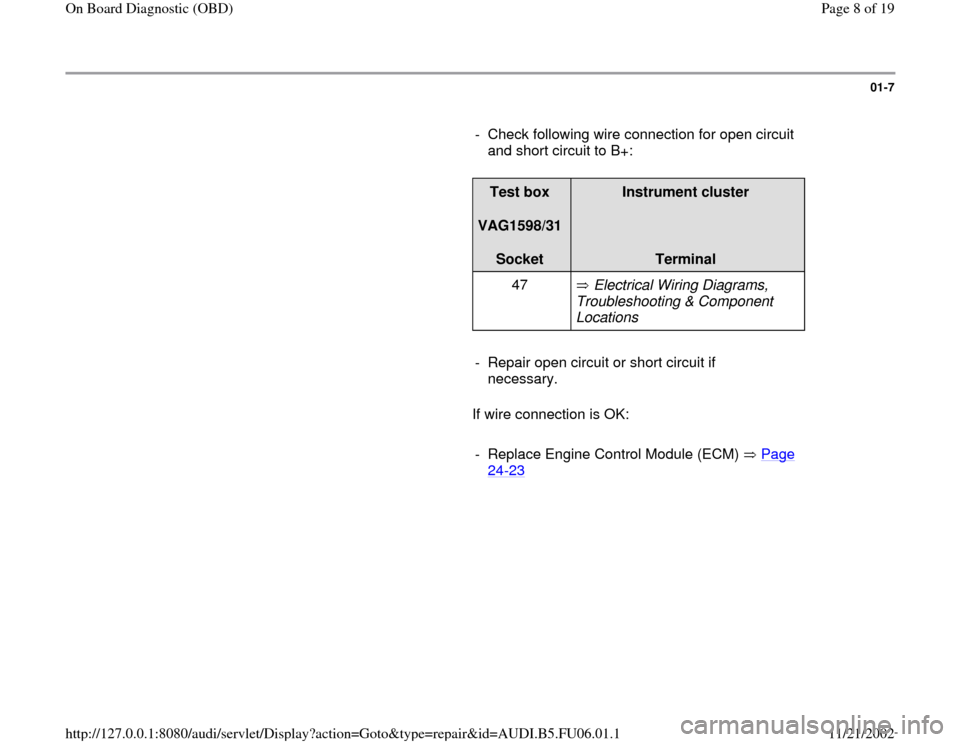
- Check following wire connection for open circuit
and short circuit to B+:
Test box
VAG1598/31
Socket
Instrument cluster
Terminal
47 Electrical Wiring Diagrams,
Troubleshooting & Component
Locations
- Repair open circuit or short circuit if
necessary.
If wire connection is OK:
- Replace Engine Control Module (ECM) Page
24
-23
Pa
ge 8 of 19 On Board Dia
gnostic
(OBD
)
11/21/2002 htt
p://127.0.0.1:8080/audi/servlet/Dis
play?action=Goto&t
yp
e=re
pair&id=AUDI.B5.FU06.01.1
Page 9 of 19
01-8
B- Exhaust MIL remains constantly lit
- Check DTC memory of Engine Control Module
(ECM) Page 01
-16
.
If no DTCs are stored:
- Connect VAG1598/31 test box at wiring harness
to Engine Control Module (ECM), do not connect
ECM Page 24
-19
.
- Remove instrument cluster:
Repair Manual, Electrical Equipment, Repair
Group 90; Instrument cluster, removing and installing
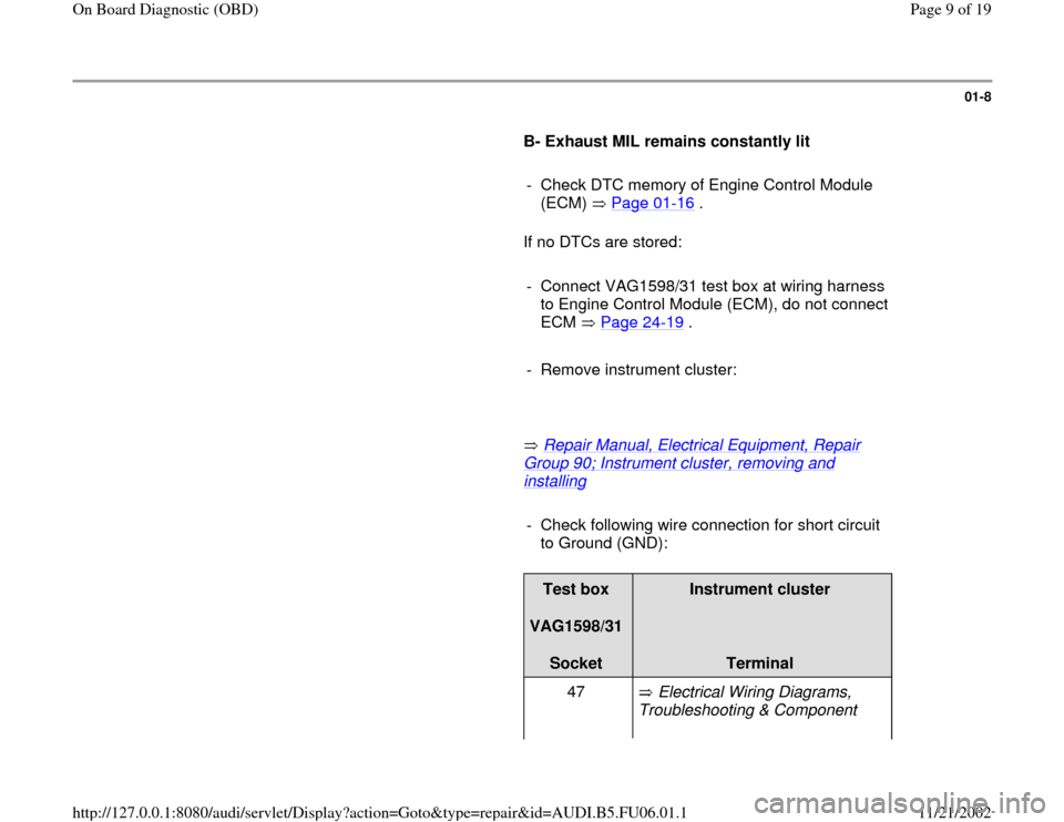
- Check following wire connection for short circuit
to Ground (GND):
Test box
VAG1598/31
Socket
Instrument cluster
Terminal
47 Electrical Wiring Diagrams,
Troubleshooting & Component
Pa
ge 9 of 19 On Board Dia
gnostic
(OBD
)
11/21/2002 htt
p://127.0.0.1:8080/audi/servlet/Dis
play?action=Goto&t
yp
e=re
pair&id=AUDI.B5.FU06.01.1
Page 10 of 19
Locations
- Repair short circuit if necessary.
If wire connection is OK:
- Replace Engine Control Module (ECM) Page
24
-23
Pa
ge 10 of 19 On Board Dia
gnostic
(OBD
)
11/21/2002 htt
p://127.0.0.1:8080/audi/servlet/Dis
play?action=Goto&t
yp
e=re
pair&id=AUDI.B5.FU06.01.1
Trending: automatic transmission, instrument cluster, fuses, fuel, buttons, battery, battery location
