differential AUDI A6 2000 C5 / 2.G Changing Clutch 5Speed Manual Gearbox
[x] Cancel search | Manufacturer: AUDI, Model Year: 2000, Model line: A6, Model: AUDI A6 2000 C5 / 2.GPages: 71, PDF Size: 1.82 MB
Page 44 of 71
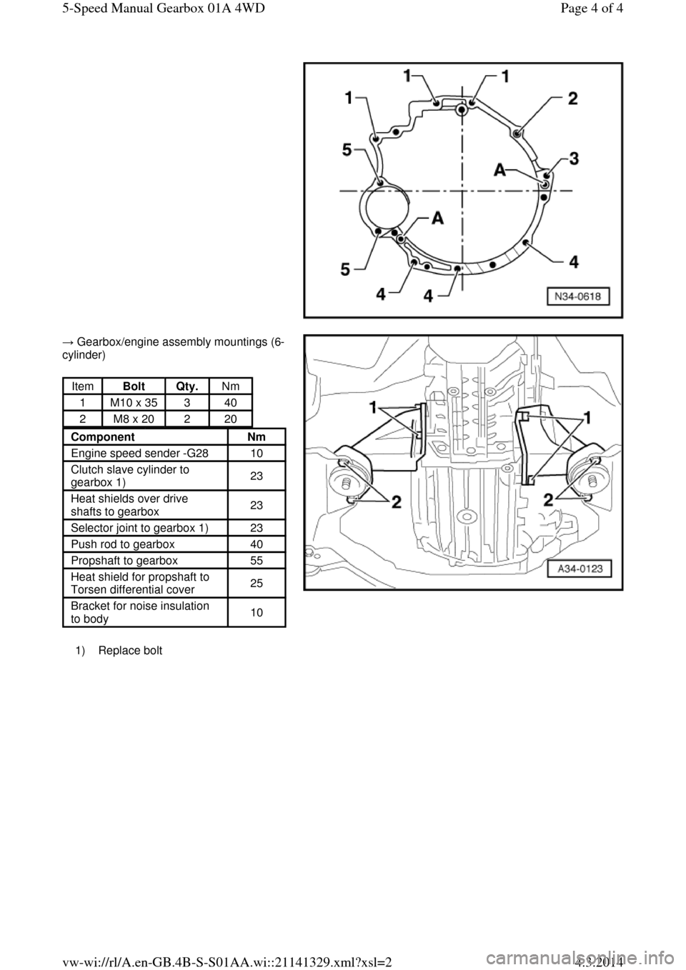
→ Gearbox/engine assembly mountings (6-
cylinder) 1) Replace bolt Item Bolt Qty. Nm
1 M10 x 35 3 40
2 M8 x 20 2 20 Component Nm
Engine speed sender -G28 10
Clutch slave cylinder to
gearbox 1) 23
Heat shields over drive
shafts to gearbox 23
Selector joint to gearbox 1) 23
Push rod to gearbox 40
Propshaft to gearbox 55
Heat shield for propshaft to
Torsen differential cover 25
Bracket for noise insulation
to body 10 Page 4 of 45-Speed Manual Gearbox 01A 4WD4.3.2014vw-wi://rl/A.en-GB.4B-S-S01AA.wi::21141329.xml?xsl=2
Page 45 of 71
Removing and installing cover with Torsen differential Removing and installing cover with Torsen differential
● Gearbox installed
Removing
Vehicles with 4-cylinder engine:
‒ Remove rear section of exhaust system from clamp(s):
=> 4-cylinder Engine (5-valve turbo), Mechanical Components; Repair group 26; Removing and installing parts of exhaust system
Vehicles with 6-cylinder engine:
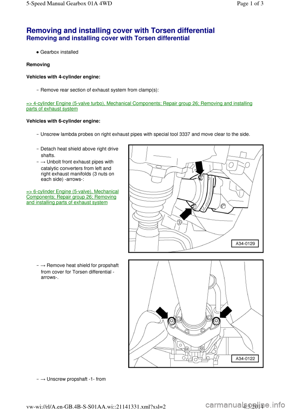
‒ Unscrew lambda probes on right exhaust pipes with special tool 3337 and move clear to the side. ‒ Detach heat shield above right drive
shafts.
‒ → Unbolt front exhaust pipes with
catalytic converters from left and
right exhaust manifolds (3 nuts on
each side) -arrows-:
=> 6-cylinder Engine (5-valve), Mechanical Components; Repair group 26; Removing and installing parts of exhaust system ‒ → Remove heat shield for propshaft
from cover for Torsen differential -
arrows-. ‒ → Unscrew propshaft -1- from Page 1 of 35-Speed Manual Gearbox 01A 4WD4.3.2014vw-wi://rl/A.en-GB.4B-S-S01AA.wi::21141331.xml?xsl=2
Page 46 of 71
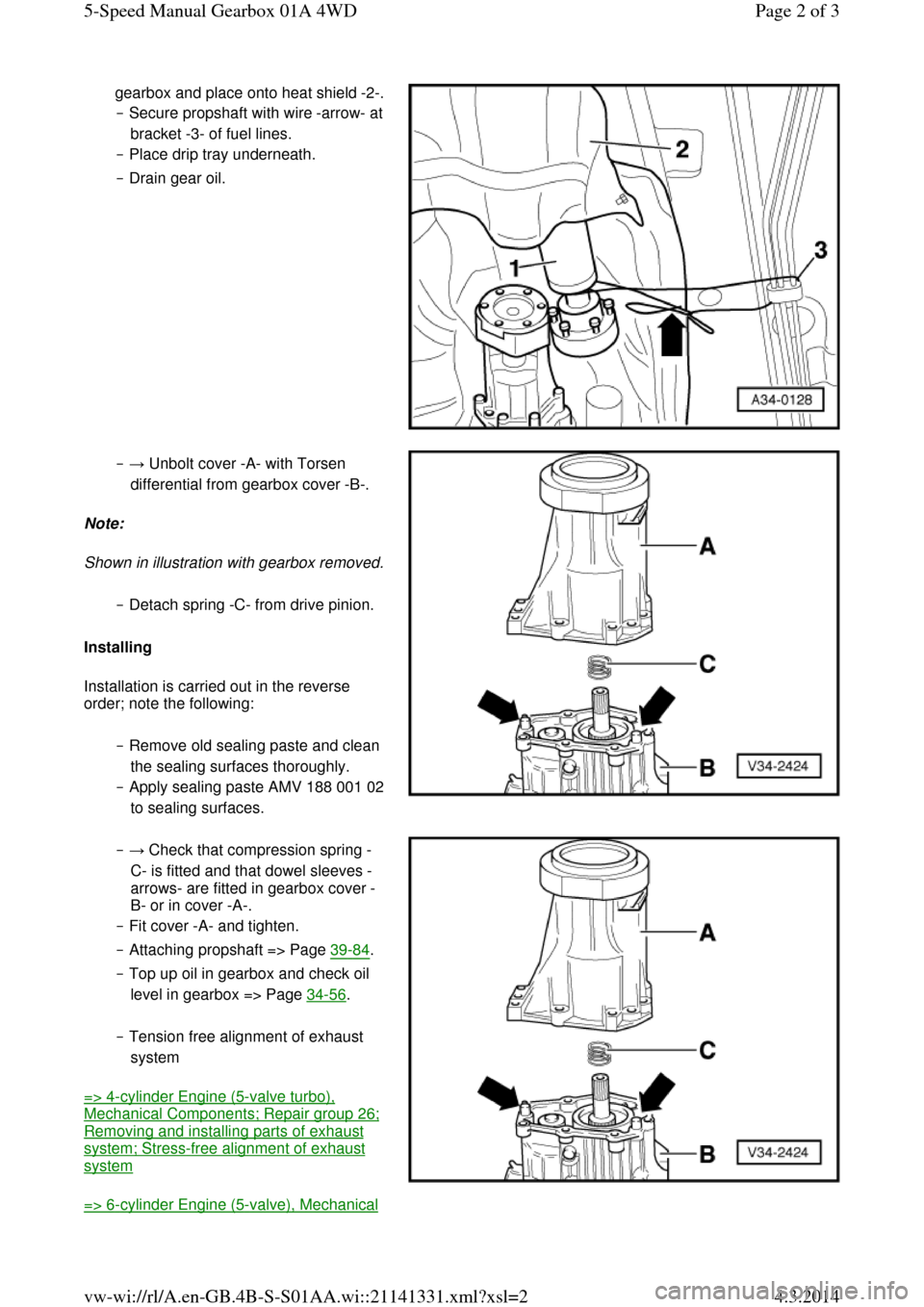
gearbox and place onto heat shield -2-. ‒ Secure propshaft with wire -arrow- at bracket -3- of fuel lines.
‒ Place drip tray underneath.
‒ Drain gear oil. ‒ → Unbolt cover -A- with Torsen
differential from gearbox cover -B-.
Note:
Shown in illustration with gearbox removed. ‒ Detach spring -C- from drive pinion.
Installing
Installation is carried out in the reverse
order; note the following:
‒ Remove old sealing paste and clean
the sealing surfaces thoroughly.
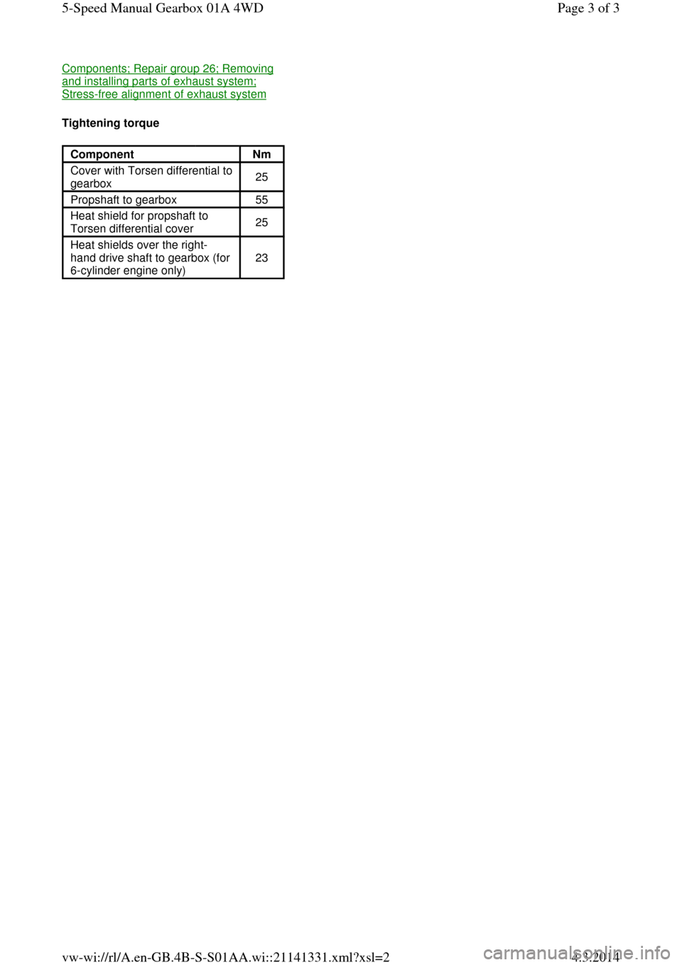
‒ Apply sealing paste AMV 188 001 02 to sealing surfaces. ‒ → Check that compression spring -
C- is fitted and that dowel sleeves -
arrows- are fitted in gearbox cover -
B- or in cover -A-.
‒ Fit cover -A- and tighten.
‒ Attaching propshaft => Page 39-84.
‒ Top up oil in gearbox and check oil
level in gearbox => Page 34-56.
‒ Tension free alignment of exhaust
system
=> 4-cylinder Engine (5-valve turbo), Mechanical Components; Repair group 26; Removing and installing parts of exhaust system; Stress-free alignment of exhaust system
=> 6-cylinder Engine (5-valve), Mechanical Page 2 of 35-Speed Manual Gearbox 01A 4WD4.3.2014vw-wi://rl/A.en-GB.4B-S-S01AA.wi::21141331.xml?xsl=2
Page 47 of 71
Components; Repair group 26; Removing and installing parts of exhaust system; Stress-free alignment of exhaust system
Tightening torque
Component Nm
Cover with Torsen differential to
gearbox 25
Propshaft to gearbox 55
Heat shield for propshaft to
Torsen differential cover 25
Heat shields over the right-
hand drive shaft to gearbox (for
6-cylinder engine only) 23 Page 3 of 35-Speed Manual Gearbox 01A 4WD4.3.2014vw-wi://rl/A.en-GB.4B-S-S01AA.wi::21141331.xml?xsl=2
Page 54 of 71
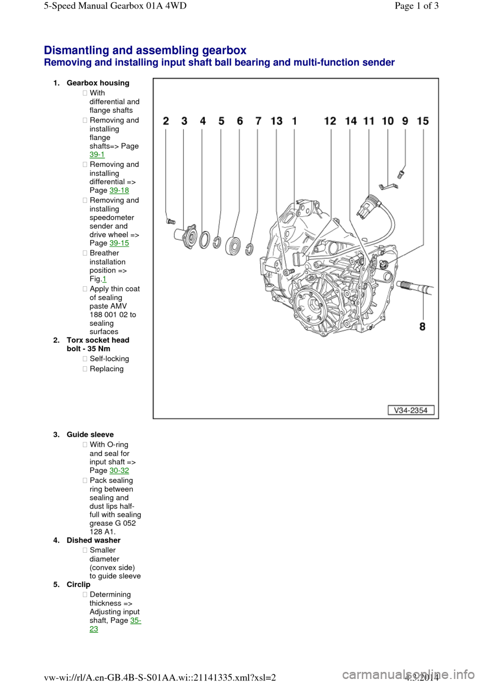
Dismantling and assembling gearbox Removing and installing input shaft ball bearing and multi-function sender 1.Gearbox housing ◆ With differential and flange shafts
◆ Removing and
installing
flange
shafts=> Page
39-1
◆ Removing and
installing
differential =>
Page 39-18
◆ Removing and
installing
speedometer
sender and
drive wheel =>
Page 39-15
◆ Breather
installation
position =>
Fig.1
◆ Apply thin coat of sealing
paste AMV
188 001 02 to
sealing
surfaces
2.Torx socket head
bolt - 35 Nm
◆ Self-locking
◆ Replacing
3.Guide sleeve ◆ With O-ring
and seal for
input shaft =>
Page 30-32
◆ Pack sealing
ring between
sealing and
dust lips half-full with sealing grease G 052
128 A1.
4.Dished washer
◆ Smaller
diameter
(convex side) to guide sleeve 5.Circlip
◆ Determining
thickness => Adjusting input shaft, Page 35-23 Page 1 of 35-Speed Manual Gearbox 01A 4WD4.3.2014vw-wi://rl/A.en-GB.4B-S-S01AA.wi::21141335.xml?xsl=2
Page 57 of 71
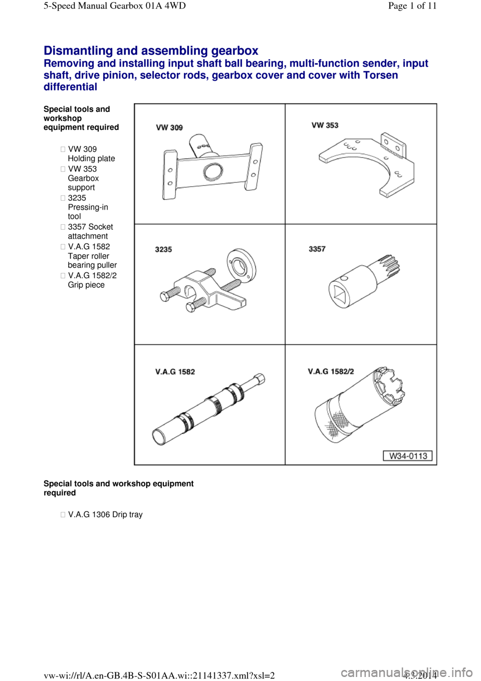
Dismantling and assembling gearbox Removing and installing input shaft ball bearing, multi-function sender, input
shaft, drive pinion, selector rods, gearbox cover and cover with Torsen differential Special tools and workshop
equipment required
◆ VW 309
Holding plate
◆ VW 353
Gearbox
support
◆ 3235
Pressing-in
tool
◆ 3357 Socket
attachment
◆ V.A.G 1582
Taper roller
bearing puller
◆ V.A.G 1582/2
Grip piece Special tools and workshop equipment required
◆ V.A.G 1306 Drip tray Page 1 of 115-Speed Manual Gearbox 01A 4WD4.3.2014vw-wi://rl/A.en-GB.4B-S-S01AA.wi::21141337.xml?xsl=2
Page 58 of 71

◆ V.A.G 1331 Torque wrench
◆ Sealant AMV 188 001 02 Notes:
◆ It is not necessary to remove the
differential to remove the above-
mentioned components => Page 34-74.
◆ Removal is only necessary when
adjustments have to be carried out
=> adjustment overview, Page 39-45.
Removing
‒ Place drip tray V.A.G 1306
underneath the gearbox.
‒ Drain gearbox oil using socket
attachment 3357.
‒ → Secure gearbox in assembly
stand VW 540. Page 2 of 115-Speed Manual Gearbox 01A 4WD4.3.2014vw-wi://rl/A.en-GB.4B-S-S01AA.wi::21141337.xml?xsl=2
Page 60 of 71
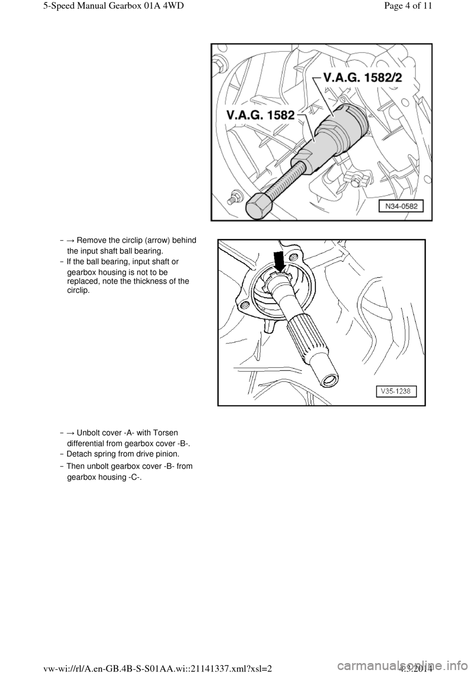
‒ → Remove the circlip (arrow) behind
the input shaft ball bearing.
‒ If the ball bearing, input shaft or
gearbox housing is not to be
replaced, note the thickness of the
circlip. ‒ → Unbolt cover -A- with Torsen
differential from gearbox cover -B-.
‒ Detach spring from drive pinion.
‒ Then unbolt gearbox cover -B- from
gearbox housing -C-. Page 4 of 115-Speed Manual Gearbox 01A 4WD4.3.2014vw-wi://rl/A.en-GB.4B-S-S01AA.wi::21141337.xml?xsl=2
Page 66 of 71

cover -A- are fitted in gearbox cover -
B- (arrows).
‒ Fit spring -C-.
‒ Apply thin coat of sealant AMV 188
001 02 to sealing surfaces.
‒ Fit cover with Torsen differential -A-
on gearbox cover -B-. ‒ → Fit rear input shaft ball bearing
circlip (arrow).
‒ Push the ball bearing onto the input
shaft.
‒ Installation position: closed
side of ball cage faces
towards gearbox housing ‒ → Press in ball bearing:
‒ Push thrust pad -A- of pressing-in
tool onto input shaft.
‒ Position pressing-in tool behind
splines for clutch plate.
‒ Screw in the bolts -B- until they make contact.
‒ The bolts bear against the
indentations in thrust pad -A-. ‒ Press in ball bearing onto its seat by
alternately tightening the bolts (1/2
turn at a time). ‒ → Now fit the front circlip -D- for the Page 10 of 115-Speed Manual Gearbox 01A 4WD4.3.2014vw-wi://rl/A.en-GB.4B-S-S01AA.wi::21141337.xml?xsl=2
Page 68 of 71
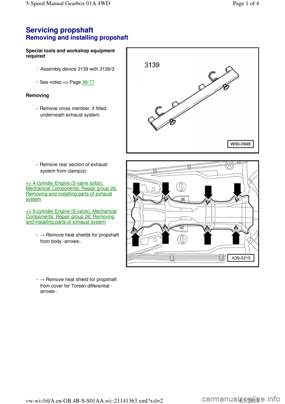
Servicing propshaft Removing and installing propshaft Special tools and workshop equipment required
◆ Assembly device 3139 with 3139/3
‒ See notes => Page 39-77
Removing
‒ Remove cross member, if fitted,
underneath exhaust system. ‒ Remove rear section of exhaust
system from clamp(s):
=> 4-cylinder Engine (5-valve turbo), Mechanical Components; Repair group 26; Removing and installing parts of exhaust system
=> 6-cylinder Engine (5-valve), Mechanical Components; Repair group 26; Removing and installing parts of exhaust system
‒ → Remove heat shields for propshaft from body -arrows-. ‒ → Remove heat shield for propshaft
from cover for Torsen differential -
arrows-. Page 1 of 45-Speed Manual Gearbox 01A 4WD4.3.2014vw-wi://rl/A.en-GB.4B-S-S01AA.wi::21141363.xml?xsl=2