check engine AUDI A6 2000 C5 / 2.G Changing Clutch 5Speed Manual Gearbox
[x] Cancel search | Manufacturer: AUDI, Model Year: 2000, Model line: A6, Model: AUDI A6 2000 C5 / 2.GPages: 71, PDF Size: 1.82 MB
Page 32 of 71
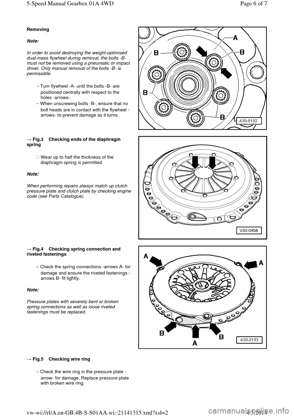
Removing Note:
In order to avoid destroying the weight-optimised
dual-mass flywheel during removal, the bolts -B-
must not be removed using a pneumatic or impact
driver. Only manual removal of the bolts -B- is permissible.
‒ Turn flywheel -A- until the bolts -B- are
positioned centrally with respect to the
holes -arrows-.
‒ When unscrewing bolts -B-, ensure that no
bolt heads are in contact with the flywheel -
arrows- to prevent damage as it turns. → Fig.3 Checking ends of the diaphragm spring
◆ Wear up to half the thickness of the
diaphragm spring is permitted.
Note:
When performing repairs always match up clutch pressure plate and clutch plate by checking engine code (see Parts Catalogue).
→ Fig.4 Checking spring connection and riveted fastenings
‒ Check the spring connections -arrows A- for damage and ensure the riveted fastenings -
arrows B- fit tightly.
Note:
Pressure plates with severely bent or broken
spring connections as well as loose riveted
fastenings must be replaced.
→ Fig.5 Checking wire ring ‒ Check the wire ring in the pressure plate -
arrow- for damage. Replace pressure plate
with broken wire ring. Page 6 of 75-Speed Manual Gearbox 01A 4WD4.3.2014vw-wi://rl/A.en-GB.4B-S-S01AA.wi::21141315.xml?xsl=2
Page 41 of 71
Removing gearbox Installing
Installation is carried out in the reverse order; note the following:
‒ Clean input shaft splines and (in the case of used clutch plates) the hub splines. Remove corrosion and apply only a very thin coating of grease G 000 100 to the splines. Do not grease guide sleeve. It should be possible to push the clutch
plate back and forth slightly.
‒ Check clutch release bearing for
wear, replace if necessary.
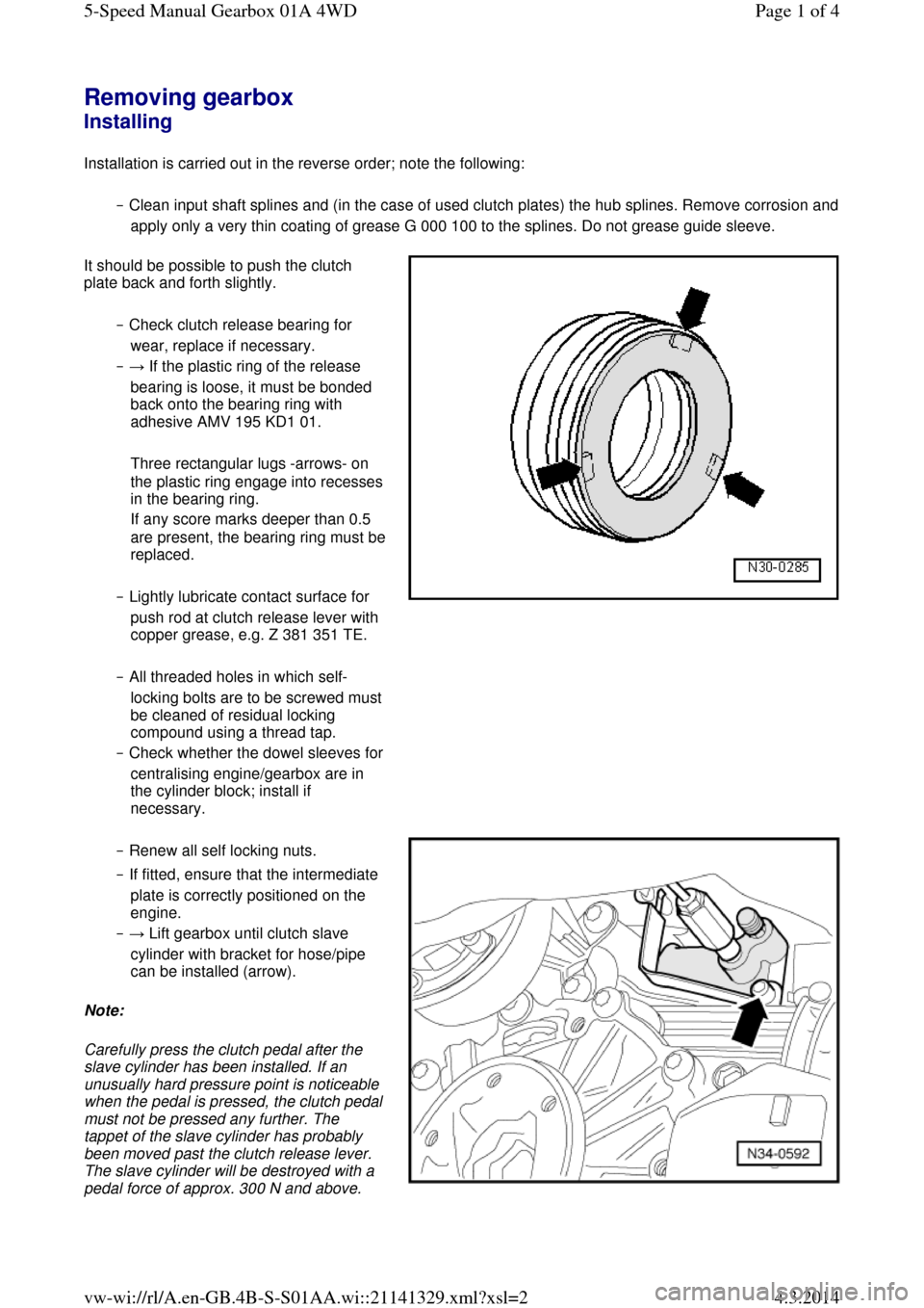
‒ → If the plastic ring of the release
bearing is loose, it must be bonded
back onto the bearing ring with
adhesive AMV 195 KD1 01.
Three rectangular lugs -arrows- on the plastic ring engage into recesses in the bearing ring.
If any score marks deeper than 0.5 are present, the bearing ring must be replaced.
‒ Lightly lubricate contact surface for
push rod at clutch release lever with
copper grease, e.g. Z 381 351 TE.
‒ All threaded holes in which self-locking bolts are to be screwed must be cleaned of residual locking
compound using a thread tap.
‒ Check whether the dowel sleeves for centralising engine/gearbox are in
the cylinder block; install if
necessary. ‒ Renew all self locking nuts.
‒ If fitted, ensure that the intermediate
plate is correctly positioned on the
engine.
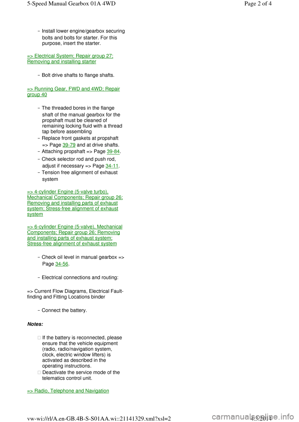
‒ → Lift gearbox until clutch slave
cylinder with bracket for hose/pipe
can be installed (arrow).
Note:
Carefully press the clutch pedal after the
slave cylinder has been installed. If an
unusually hard pressure point is noticeable when the pedal is pressed, the clutch pedal must not be pressed any further. The
tappet of the slave cylinder has probably
been moved past the clutch release lever.
The slave cylinder will be destroyed with a pedal force of approx. 300 N and above. Page 1 of 45-Speed Manual Gearbox 01A 4WD4.3.2014vw-wi://rl/A.en-GB.4B-S-S01AA.wi::21141329.xml?xsl=2
Page 42 of 71
‒ Install lower engine/gearbox securing bolts and bolts for starter. For this
purpose, insert the starter.
=> Electrical System; Repair group 27; Removing and installing starter
‒ Bolt drive shafts to flange shafts.
=> Running Gear, FWD and 4WD; Repair group 40
‒ The threaded bores in the flange
shaft of the manual gearbox for the
propshaft must be cleaned of
remaining locking fluid with a thread
tap before assembling
‒ Replace front gaskets at propshaft
=> Page 39-79 and at drive shafts.
‒ Attaching propshaft => Page 39-84.
‒ Check selector rod and push rod,
adjust if necessary => Page 34-11.
‒ Tension free alignment of exhaust
system
=> 4-cylinder Engine (5-valve turbo), Mechanical Components; Repair group 26; Removing and installing parts of exhaust system; Stress-free alignment of exhaust system
=> 6-cylinder Engine (5-valve), Mechanical Components; Repair group 26; Removing and installing parts of exhaust system; Stress-free alignment of exhaust system
‒ Check oil level in manual gearbox => Page 34-56.
‒ Electrical connections and routing:
=> Current Flow Diagrams, Electrical Fault-
finding and Fitting Locations binder
‒ Connect the battery.
Notes:
◆ If the battery is reconnected, please
ensure that the vehicle equipment
(radio, radio/navigation system,
clock, electric window lifters) is
activated as described in the
operating instructions.
◆ Deactivate the service mode of the
telematics control unit.
=> Radio, Telephone and Navigation Page 2 of 45-Speed Manual Gearbox 01A 4WD4.3.2014vw-wi://rl/A.en-GB.4B-S-S01AA.wi::21141329.xml?xsl=2
Page 46 of 71
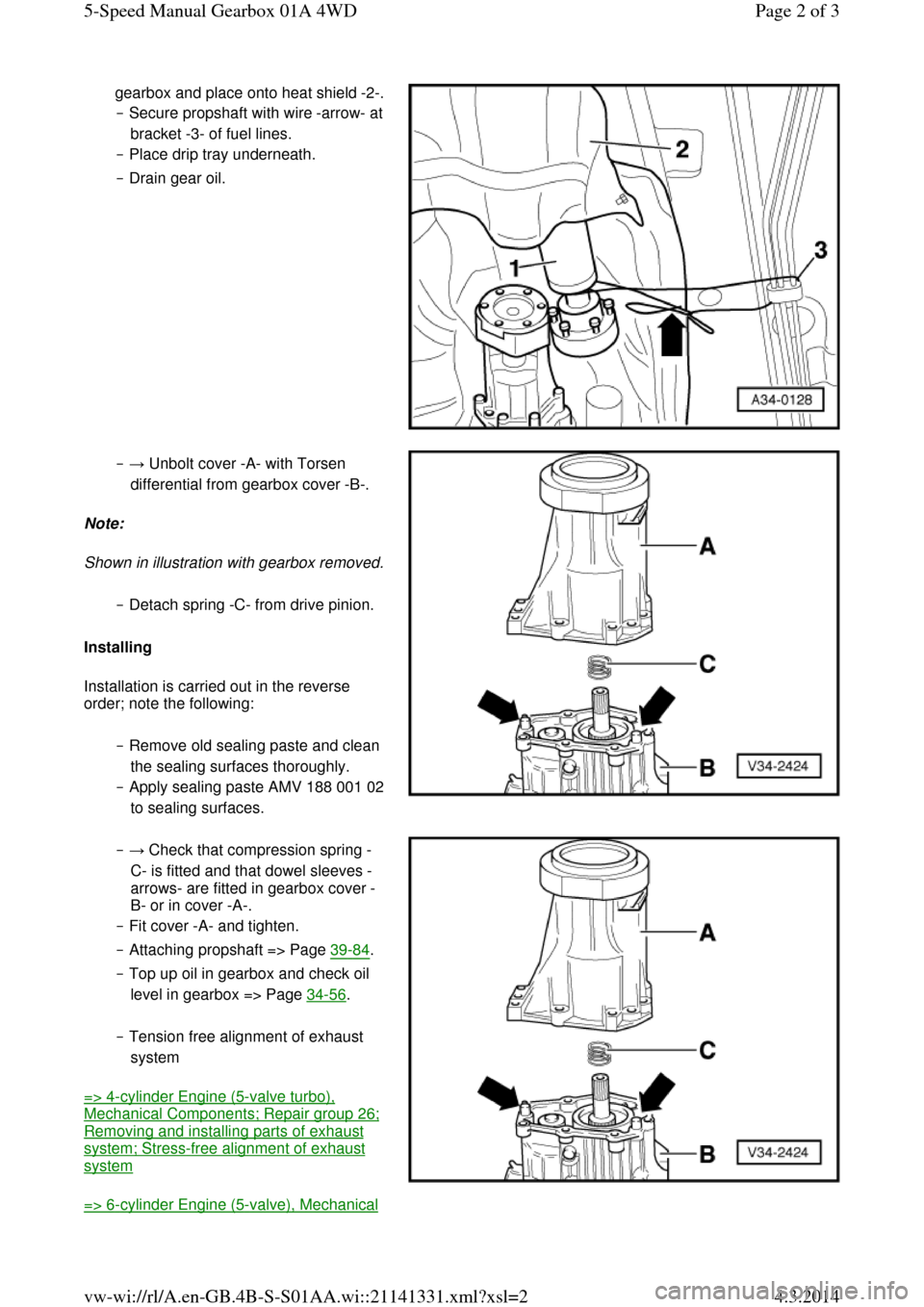
gearbox and place onto heat shield -2-. ‒ Secure propshaft with wire -arrow- at bracket -3- of fuel lines.
‒ Place drip tray underneath.
‒ Drain gear oil. ‒ → Unbolt cover -A- with Torsen
differential from gearbox cover -B-.
Note:
Shown in illustration with gearbox removed. ‒ Detach spring -C- from drive pinion.
Installing
Installation is carried out in the reverse
order; note the following:
‒ Remove old sealing paste and clean
the sealing surfaces thoroughly.
‒ Apply sealing paste AMV 188 001 02 to sealing surfaces. ‒ → Check that compression spring -
C- is fitted and that dowel sleeves -
arrows- are fitted in gearbox cover -
B- or in cover -A-.
‒ Fit cover -A- and tighten.
‒ Attaching propshaft => Page 39-84.
‒ Top up oil in gearbox and check oil
level in gearbox => Page 34-56.
‒ Tension free alignment of exhaust
system
=> 4-cylinder Engine (5-valve turbo), Mechanical Components; Repair group 26; Removing and installing parts of exhaust system; Stress-free alignment of exhaust system
=> 6-cylinder Engine (5-valve), Mechanical Page 2 of 35-Speed Manual Gearbox 01A 4WD4.3.2014vw-wi://rl/A.en-GB.4B-S-S01AA.wi::21141331.xml?xsl=2
Page 49 of 71
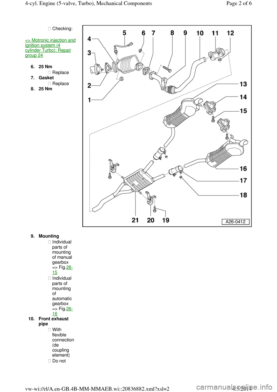
◆ Checking: => Motronic injection and ignition system (4 cylinder Turbo); Repair group 24
6.25 Nm
◆ Replace
7.Gasket
◆ Replace
8.25 Nm 9.Mounting ◆ Individual
parts of
mounting
of manual
gearbox
=> Fig.26-15
◆ Individual
parts of
mounting
of
automatic
gearbox
=> Fig.26-16
10.Front exhaust
pipe
◆ With
flexible
connection
(de
coupling
element)
◆ Do not Page 2 of 64-cyl. Engine (5-valve, Turbo), Mechanical Components4.3.2014vw-wi://rl/A.en-GB.4B-MM-MMAEB.wi::20836882.xml?xsl=2