light AUDI A6 2000 C5 / 2.G Changing Clutch 5Speed Manual Gearbox
[x] Cancel search | Manufacturer: AUDI, Model Year: 2000, Model line: A6, Model: AUDI A6 2000 C5 / 2.GPages: 71, PDF Size: 1.82 MB
Page 9 of 71
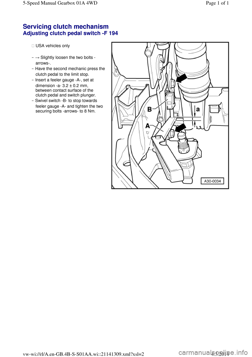
Servicing clutch mechanism Adjusting clutch pedal switch -F 194 ◆ USA vehicles only
‒ → Slightly loosen the two bolts -
arrows-.
‒ Have the second mechanic press the clutch pedal to the limit stop.
‒ Insert a feeler gauge -A-, set at
dimension -a- 3.2 ± 0.2 mm,
between contact surface of the
clutch pedal and switch plunger.
‒ Swivel switch -B- to stop towards
feeler gauge -A- and tighten the two
securing bolts -arrows- to 8 Nm. Page 1 of 15-Speed Manual Gearbox 01A 4WD4.3.2014vw-wi://rl/A.en-GB.4B-S-S01AA.wi::21141309.xml?xsl=2
Page 11 of 71
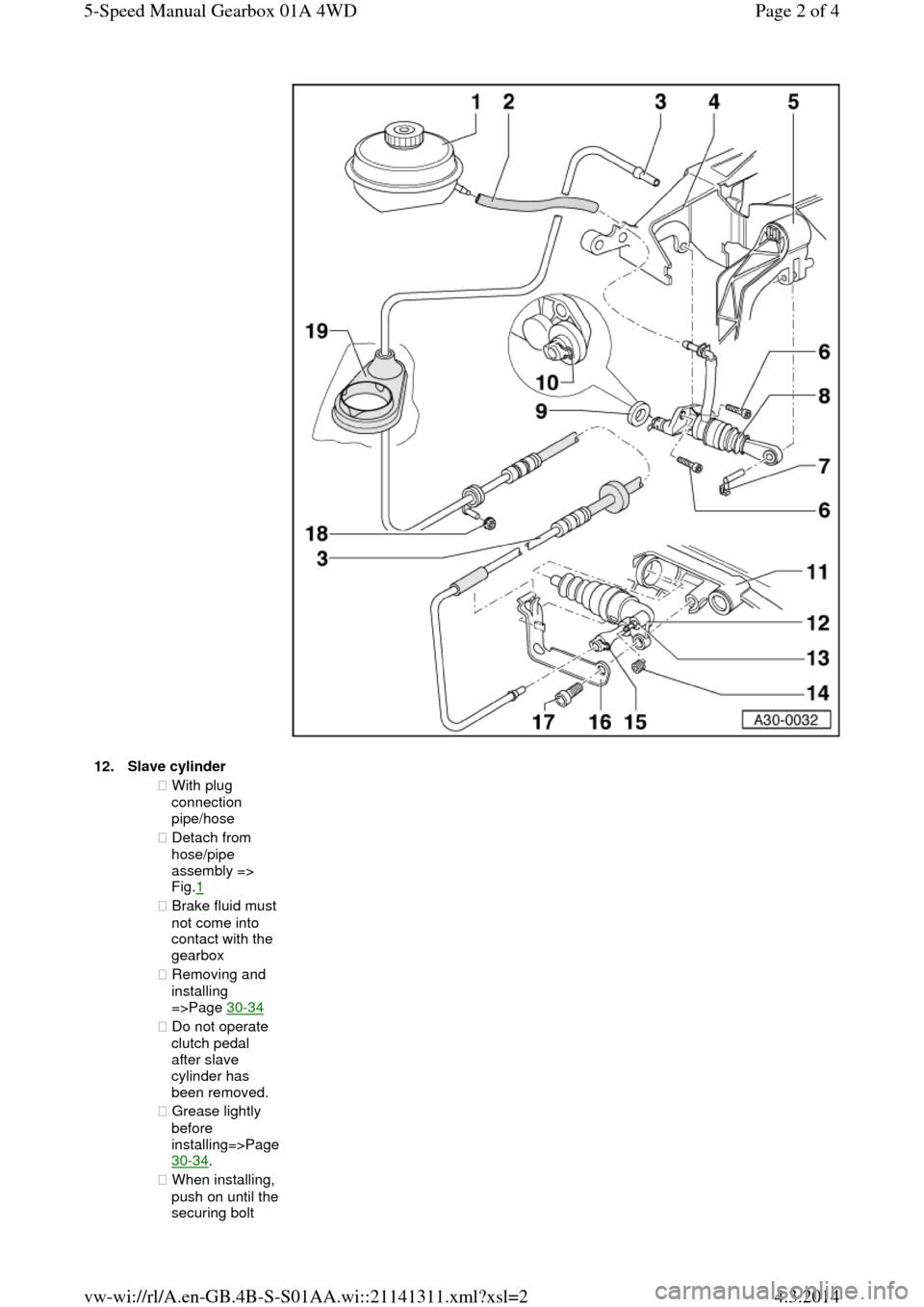
12.Slave cylinder ◆ With plug
connection
pipe/hose
◆ Detach from
hose/pipe
assembly =>
Fig.1
◆ Brake fluid must not come into
contact with the
gearbox
◆ Removing and
installing
=>Page 30-34
◆ Do not operate
clutch pedal
after slave
cylinder has
been removed.
◆ Grease lightly
before installing=>Page 30-34.
◆ When installing, push on until the securing bolt Page 2 of 45-Speed Manual Gearbox 01A 4WD4.3.2014vw-wi://rl/A.en-GB.4B-S-S01AA.wi::21141311.xml?xsl=2
Page 14 of 71
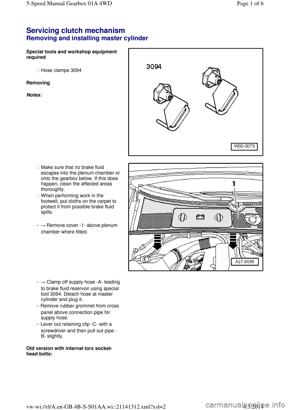
Servicing clutch mechanism Removing and installing master cylinder Special tools and workshop equipment required
◆ Hose clamps 3094
Removing
Notes: ◆ Make sure that no brake fluid escapes into the plenum chamber or onto the gearbox below. If this does
happen, clean the affected areas
thoroughly.
◆ When performing work in the
footwell, put cloths on the carpet to
protect it from possible brake fluid
spills.
‒ → Remove cover -1- above plenum
chamber where fitted. ‒ → Clamp off supply hose -A- leading to brake fluid reservoir using special
tool 3094. Detach hose at master
cylinder and plug it.
‒ Remove rubber grommet from cross
panel above connection pipe for
supply hose.
‒ Lever out retaining clip -C- with a
screwdriver and then pull out pipe -
B- slightly.
Old version with internal torx socket-
head bolts: Page 1 of 65-Speed Manual Gearbox 01A 4WD4.3.2014vw-wi://rl/A.en-GB.4B-S-S01AA.wi::21141312.xml?xsl=2
Page 16 of 71
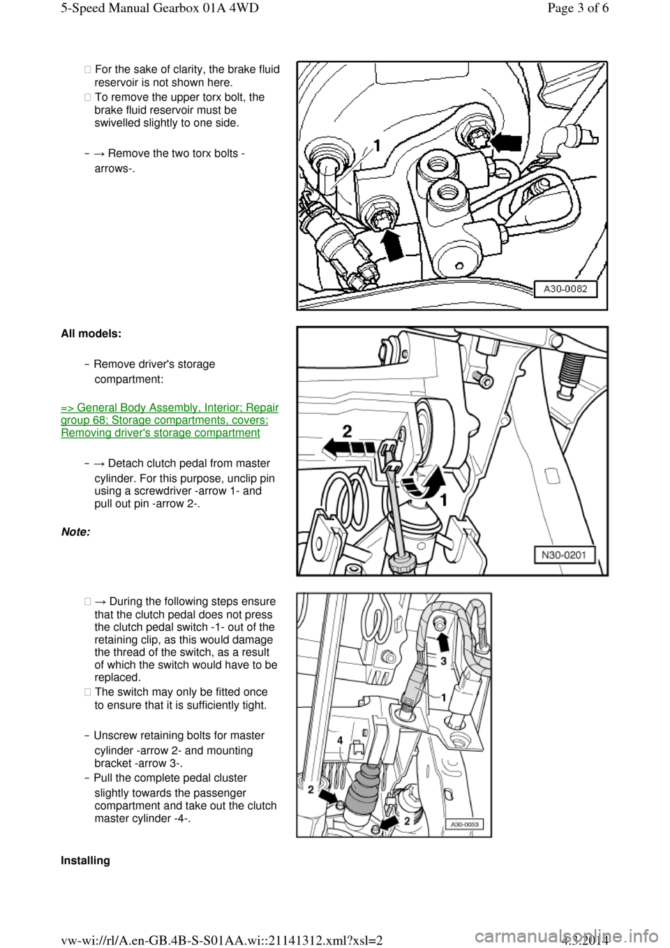
◆ For the sake of clarity, the brake fluid reservoir is not shown here.
◆ To remove the upper torx bolt, the
brake fluid reservoir must be
swivelled slightly to one side.
‒ → Remove the two torx bolts -
arrows-. All models: ‒ Remove driver's storage
compartment: => General Body Assembly, Interior; Repair group 68; Storage compartments, covers; Removing driver's storage compartment
‒ → Detach clutch pedal from master
cylinder. For this purpose, unclip pin
using a screwdriver -arrow 1- and
pull out pin -arrow 2-.
Note: ◆ → During the following steps ensure
that the clutch pedal does not press
the clutch pedal switch -1- out of the
retaining clip, as this would damage
the thread of the switch, as a result of which the switch would have to be replaced.
◆ The switch may only be fitted once
to ensure that it is sufficiently tight.
‒ Unscrew retaining bolts for master
cylinder -arrow 2- and mounting
bracket -arrow 3-.
‒ Pull the complete pedal cluster
slightly towards the passenger compartment and take out the clutch master cylinder -4-. Installing Page 3 of 65-Speed Manual Gearbox 01A 4WD4.3.2014vw-wi://rl/A.en-GB.4B-S-S01AA.wi::21141312.xml?xsl=2
Page 25 of 71
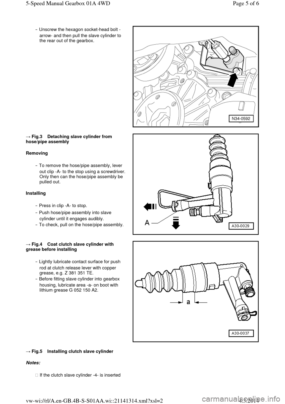
‒ Unscrew the hexagon socket-head bolt -
arrow- and then pull the slave cylinder to
the rear out of the gearbox. → Fig.3 Detaching slave cylinder from hose/pipe assembly
Removing
‒ To remove the hose/pipe assembly, lever
out clip -A- to the stop using a screwdriver. Only then can the hose/pipe assembly be
pulled out.
Installing
‒ Press in clip -A- to stop.
‒ Push hose/pipe assembly into slave
cylinder until it engages audibly.
‒ To check, pull on the hose/pipe assembly. → Fig.4 Coat clutch slave cylinder with grease before installing
‒ Lightly lubricate contact surface for push
rod at clutch release lever with copper
grease, e.g. Z 381 351 TE.
‒ Before fitting slave cylinder into gearbox
housing, lubricate area -a- on boot with
lithium grease G 052 150 A2. → Fig.5 Installing clutch slave cylinder Notes:
◆ If the clutch slave cylinder -4- is inserted Page 5 of 65-Speed Manual Gearbox 01A 4WD4.3.2014vw-wi://rl/A.en-GB.4B-S-S01AA.wi::21141314.xml?xsl=2
Page 30 of 71
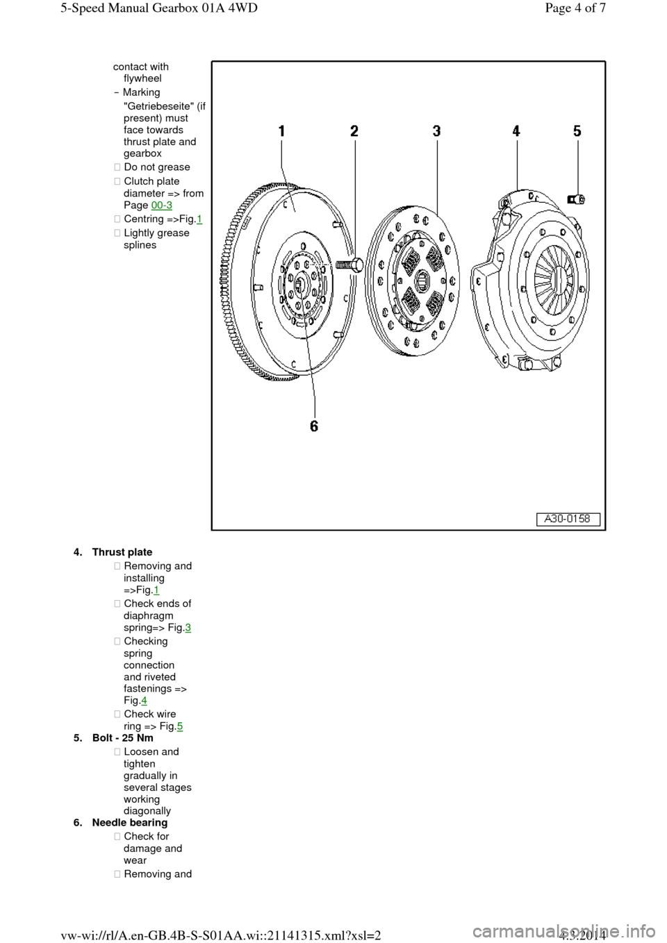
contact with
flywheel
‒ Marking "Getriebeseite" (if present) must
face towards
thrust plate and
gearbox
◆ Do not grease
◆ Clutch plate diameter => from Page 00-3
◆ Centring =>Fig.1 ◆ Lightly grease
splines 4.Thrust plate ◆ Removing and
installing
=>Fig.1
◆ Check ends of
diaphragm
spring=> Fig.3 ◆ Checking
spring
connection
and riveted
fastenings =>
Fig.4
◆ Check wire
ring => Fig.5
5.Bolt - 25 Nm
◆ Loosen and
tighten
gradually in
several stages
working
diagonally
6.Needle bearing
◆ Check for
damage and
wear
◆ Removing and Page 4 of 75-Speed Manual Gearbox 01A 4WD4.3.2014vw-wi://rl/A.en-GB.4B-S-S01AA.wi::21141315.xml?xsl=2
Page 39 of 71
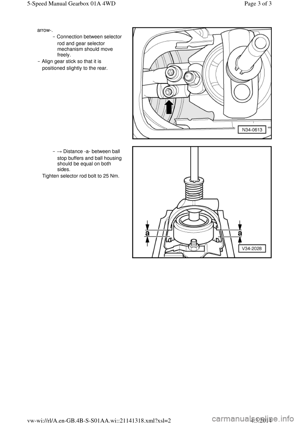
arrow-.
‒ Connection between selector
rod and gear selector
mechanism should move
freely.
‒ Align gear stick so that it is
positioned slightly to the rear. ‒ → Distance -a- between ball
stop buffers and ball housing
should be equal on both
sides.
Tighten selector rod bolt to 25 Nm. Page 3 of 35-Speed Manual Gearbox 01A 4WD4.3.2014vw-wi://rl/A.en-GB.4B-S-S01AA.wi::21141318.xml?xsl=2
Page 41 of 71
Removing gearbox Installing
Installation is carried out in the reverse order; note the following:
‒ Clean input shaft splines and (in the case of used clutch plates) the hub splines. Remove corrosion and apply only a very thin coating of grease G 000 100 to the splines. Do not grease guide sleeve. It should be possible to push the clutch
plate back and forth slightly.
‒ Check clutch release bearing for
wear, replace if necessary.
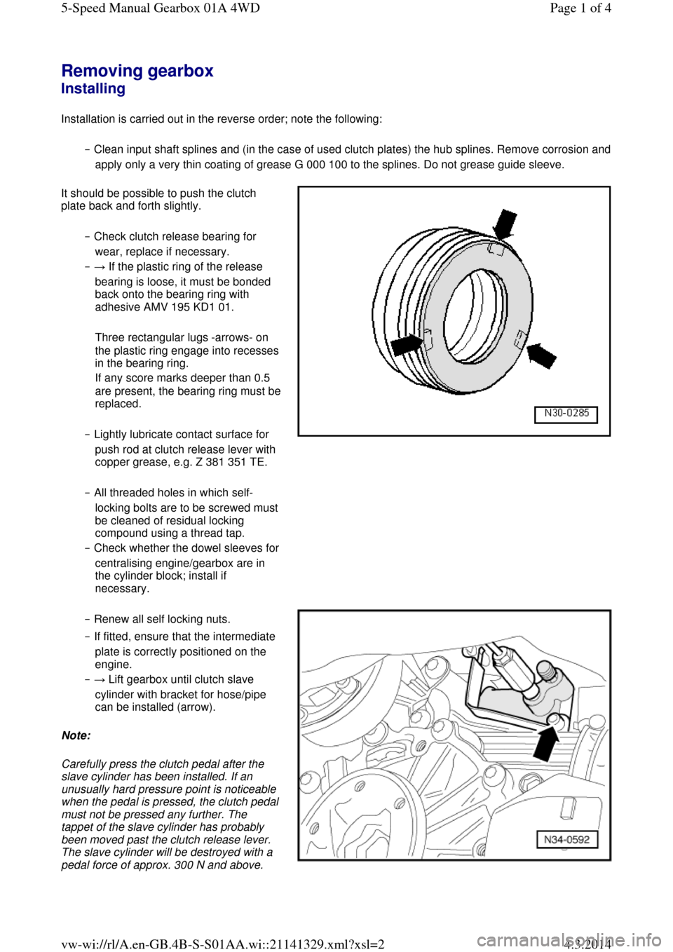
‒ → If the plastic ring of the release
bearing is loose, it must be bonded
back onto the bearing ring with
adhesive AMV 195 KD1 01.
Three rectangular lugs -arrows- on the plastic ring engage into recesses in the bearing ring.
If any score marks deeper than 0.5 are present, the bearing ring must be replaced.
‒ Lightly lubricate contact surface for
push rod at clutch release lever with
copper grease, e.g. Z 381 351 TE.
‒ All threaded holes in which self-locking bolts are to be screwed must be cleaned of residual locking
compound using a thread tap.
‒ Check whether the dowel sleeves for centralising engine/gearbox are in
the cylinder block; install if
necessary. ‒ Renew all self locking nuts.
‒ If fitted, ensure that the intermediate
plate is correctly positioned on the
engine.
‒ → Lift gearbox until clutch slave
cylinder with bracket for hose/pipe
can be installed (arrow).
Note:
Carefully press the clutch pedal after the
slave cylinder has been installed. If an
unusually hard pressure point is noticeable when the pedal is pressed, the clutch pedal must not be pressed any further. The
tappet of the slave cylinder has probably
been moved past the clutch release lever.
The slave cylinder will be destroyed with a pedal force of approx. 300 N and above. Page 1 of 45-Speed Manual Gearbox 01A 4WD4.3.2014vw-wi://rl/A.en-GB.4B-S-S01AA.wi::21141329.xml?xsl=2