wheel AUDI A6 2000 C5 / 2.G Changing Clutch 5Speed Manual Gearbox
[x] Cancel search | Manufacturer: AUDI, Model Year: 2000, Model line: A6, Model: AUDI A6 2000 C5 / 2.GPages: 71, PDF Size: 1.82 MB
Page 27 of 71
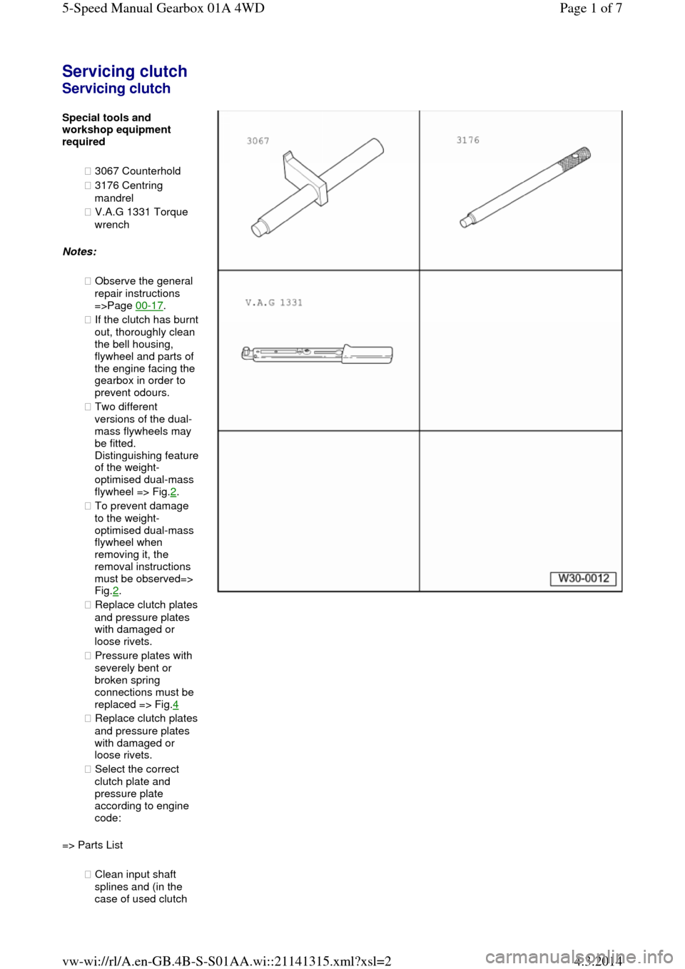
Servicing clutch Servicing clutch Special tools and workshop equipment
required
◆ 3067 Counterhold
◆ 3176 Centring
mandrel
◆ V.A.G 1331 Torque
wrench
Notes:
◆ Observe the general
repair instructions
=>Page 00-17.
◆ If the clutch has burnt out, thoroughly clean
the bell housing,
flywheel and parts of
the engine facing the
gearbox in order to
prevent odours.
◆ Two different
versions of the dual-
mass flywheels may
be fitted. Distinguishing feature of the weight-
optimised dual-mass
flywheel => Fig.2.
◆ To prevent damage
to the weight-
optimised dual-mass
flywheel when
removing it, the
removal instructions
must be observed=>
Fig.2.
◆ Replace clutch plates and pressure plates
with damaged or
loose rivets.
◆ Pressure plates with
severely bent or
broken spring
connections must be
replaced => Fig.4
◆ Replace clutch plates and pressure plates
with damaged or
loose rivets.
◆ Select the correct
clutch plate and
pressure plate
according to engine
code:
=> Parts List
◆ Clean input shaft
splines and (in the
case of used clutch Page 1 of 75-Speed Manual Gearbox 01A 4WD4.3.2014vw-wi://rl/A.en-GB.4B-S-S01AA.wi::21141315.xml?xsl=2
Page 28 of 71
plates) the hub splines.
Remove corrosion
and apply only a very thin coating of grease G 000 100 to the
splines. Then move clutch plate to and for on input shaft until
hub moves freely on
shaft. Excess grease
must be removed.
◆ Pressure plates are
protected against
corrosion and
greased. Only the
contact surface may be cleaned, otherwise the service life of the
clutch will be
considerably
reduced.
◆ Tighten securing
bolts in small steps in
diagonal sequence to
avoid damaging
centring holes in
pressure plate and
centring pins on
flywheel.
‒ Remove the gearbox
to work on the
clutch=>Page 34-35.
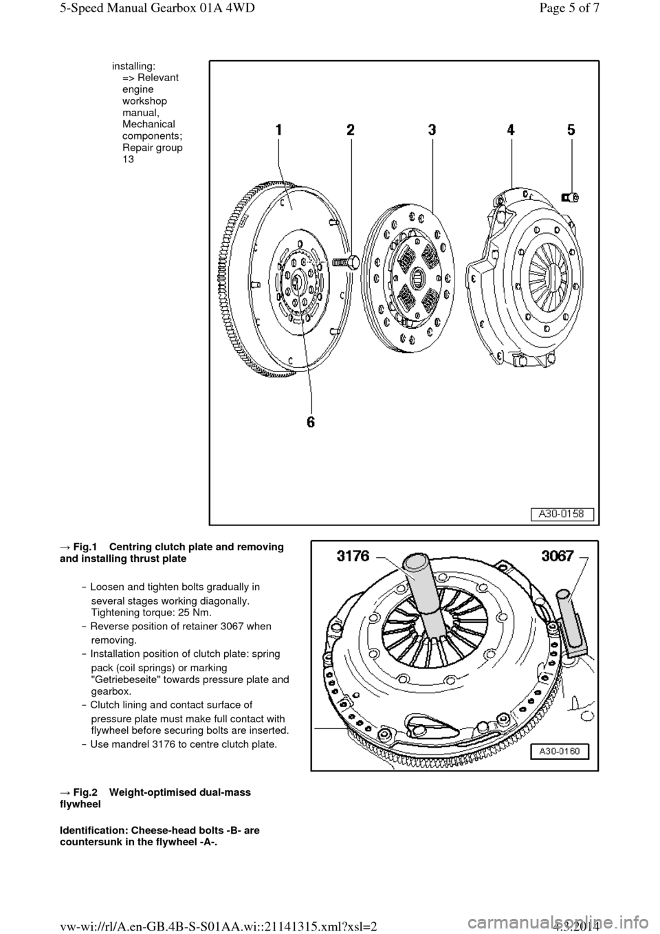
1.Flywheel/dual mass
flywheel
◆ Ensure that
centring pins
are a tight fit.
◆ Contact
surface for
clutch lining must be free of grooves, oil
and grease
◆ Observe
removal
instructions for
the weight-
optimised dual-
mass flywheel
=>Fig.2
◆ Removing and
installing:
=> Relevant
engine
workshop
manual,
Mechanical
components;
Repair group
13 Page 2 of 75-Speed Manual Gearbox 01A 4WD4.3.2014vw-wi://rl/A.en-GB.4B-S-S01AA.wi::21141315.xml?xsl=2
Page 29 of 71
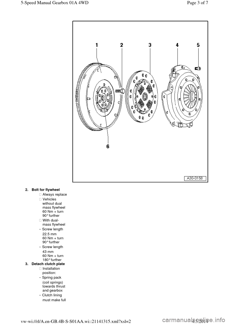
2.Bolt for flywheel ◆ Always replace ◆ Vehicles
without dual
mass flywheel
60 Nm + turn
90° further
◆ With dual-
mass flywheel ‒ Screw length
22.5 mm
60 Nm + turn
90° further
‒ Screw length
43 mm
60 Nm + turn
180° further
3.Detach clutch plate
◆ Installation
position:
‒ Spring pack
(coil springs)
towards thrust
and gearbox
‒ Clutch lining
must make full Page 3 of 75-Speed Manual Gearbox 01A 4WD4.3.2014vw-wi://rl/A.en-GB.4B-S-S01AA.wi::21141315.xml?xsl=2
Page 30 of 71
contact with
flywheel
‒ Marking "Getriebeseite" (if present) must
face towards
thrust plate and
gearbox
◆ Do not grease
◆ Clutch plate diameter => from Page 00-3
◆ Centring =>Fig.1 ◆ Lightly grease
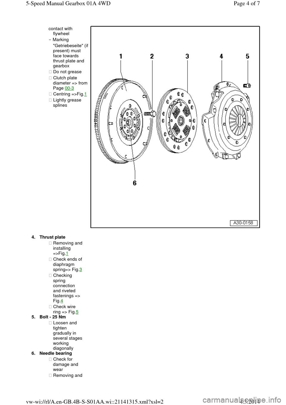
splines 4.Thrust plate ◆ Removing and
installing
=>Fig.1
◆ Check ends of
diaphragm
spring=> Fig.3 ◆ Checking
spring
connection
and riveted
fastenings =>
Fig.4
◆ Check wire
ring => Fig.5
5.Bolt - 25 Nm
◆ Loosen and
tighten
gradually in
several stages
working
diagonally
6.Needle bearing
◆ Check for
damage and
wear
◆ Removing and Page 4 of 75-Speed Manual Gearbox 01A 4WD4.3.2014vw-wi://rl/A.en-GB.4B-S-S01AA.wi::21141315.xml?xsl=2
Page 31 of 71
installing:
=> Relevant
engine
workshop
manual,
Mechanical
components;
Repair group
13 → Fig.1 Centring clutch plate and removing and installing thrust plate
‒ Loosen and tighten bolts gradually in
several stages working diagonally.
Tightening torque: 25 Nm.
‒ Reverse position of retainer 3067 when
removing.
‒ Installation position of clutch plate: spring
pack (coil springs) or marking
"Getriebeseite" towards pressure plate and
gearbox.
‒ Clutch lining and contact surface of
pressure plate must make full contact with
flywheel before securing bolts are inserted. ‒ Use mandrel 3176 to centre clutch plate.
→ Fig.2 Weight-optimised dual-mass flywheel
Identification: Cheese-head bolts -B- are
countersunk in the flywheel -A-. Page 5 of 75-Speed Manual Gearbox 01A 4WD4.3.2014vw-wi://rl/A.en-GB.4B-S-S01AA.wi::21141315.xml?xsl=2
Page 32 of 71
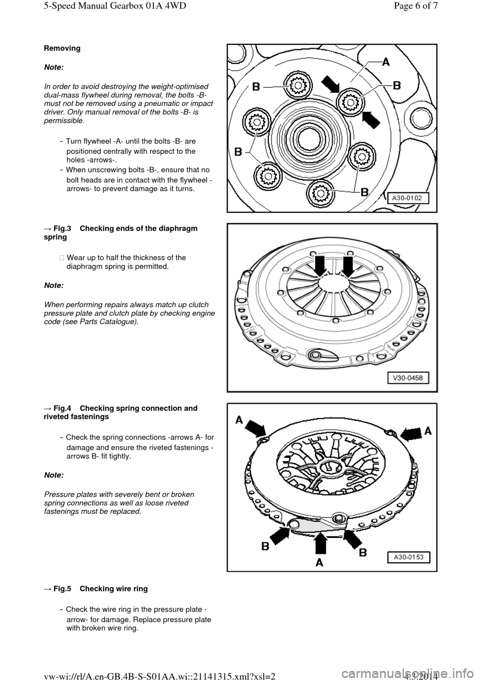
Removing Note:
In order to avoid destroying the weight-optimised
dual-mass flywheel during removal, the bolts -B-
must not be removed using a pneumatic or impact
driver. Only manual removal of the bolts -B- is permissible.
‒ Turn flywheel -A- until the bolts -B- are
positioned centrally with respect to the
holes -arrows-.
‒ When unscrewing bolts -B-, ensure that no
bolt heads are in contact with the flywheel -
arrows- to prevent damage as it turns. → Fig.3 Checking ends of the diaphragm spring
◆ Wear up to half the thickness of the
diaphragm spring is permitted.
Note:
When performing repairs always match up clutch pressure plate and clutch plate by checking engine code (see Parts Catalogue).
→ Fig.4 Checking spring connection and riveted fastenings
‒ Check the spring connections -arrows A- for damage and ensure the riveted fastenings -
arrows B- fit tightly.
Note:
Pressure plates with severely bent or broken
spring connections as well as loose riveted
fastenings must be replaced.
→ Fig.5 Checking wire ring ‒ Check the wire ring in the pressure plate -
arrow- for damage. Replace pressure plate
with broken wire ring. Page 6 of 75-Speed Manual Gearbox 01A 4WD4.3.2014vw-wi://rl/A.en-GB.4B-S-S01AA.wi::21141315.xml?xsl=2
Page 48 of 71
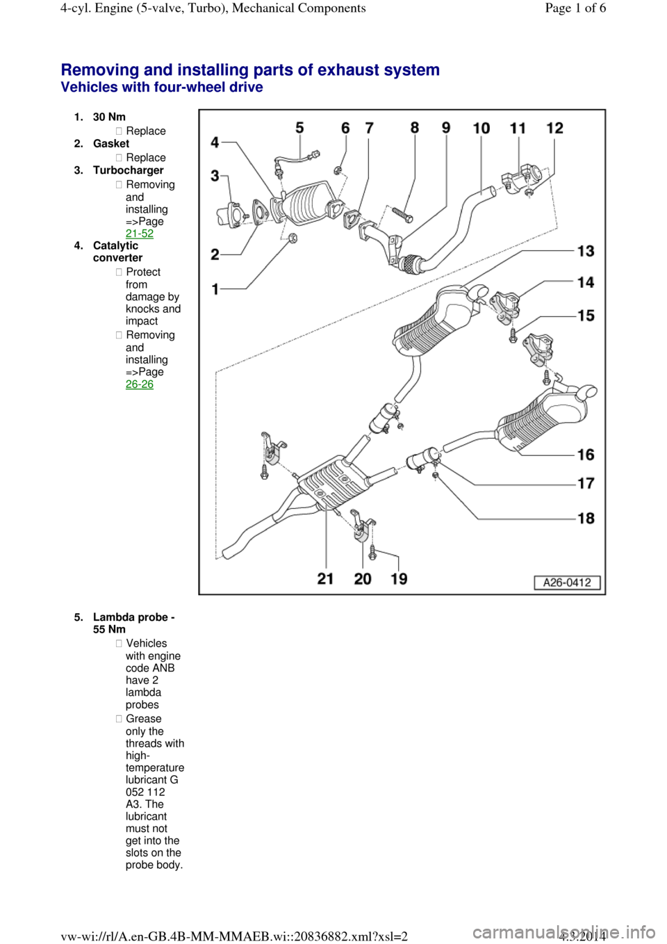
Removing and installing parts of exhaust system Vehicles with four-wheel drive 1.30 Nm ◆ Replace
2.Gasket
◆ Replace
3.Turbocharger
◆ Removing
and
installing
=>Page
21-52
4.Catalytic
converter
◆ Protect
from damage by knocks and impact
◆ Removing
and
installing
=>Page
26-26
5.Lambda probe - 55 Nm
◆ Vehicles
with engine
code ANB
have 2
lambda
probes
◆ Grease
only the threads with high-temperature lubricant G
052 112
A3. The
lubricant
must not
get into the
slots on the probe body. Page 1 of 64-cyl. Engine (5-valve, Turbo), Mechanical Components4.3.2014vw-wi://rl/A.en-GB.4B-MM-MMAEB.wi::20836882.xml?xsl=2
Page 54 of 71
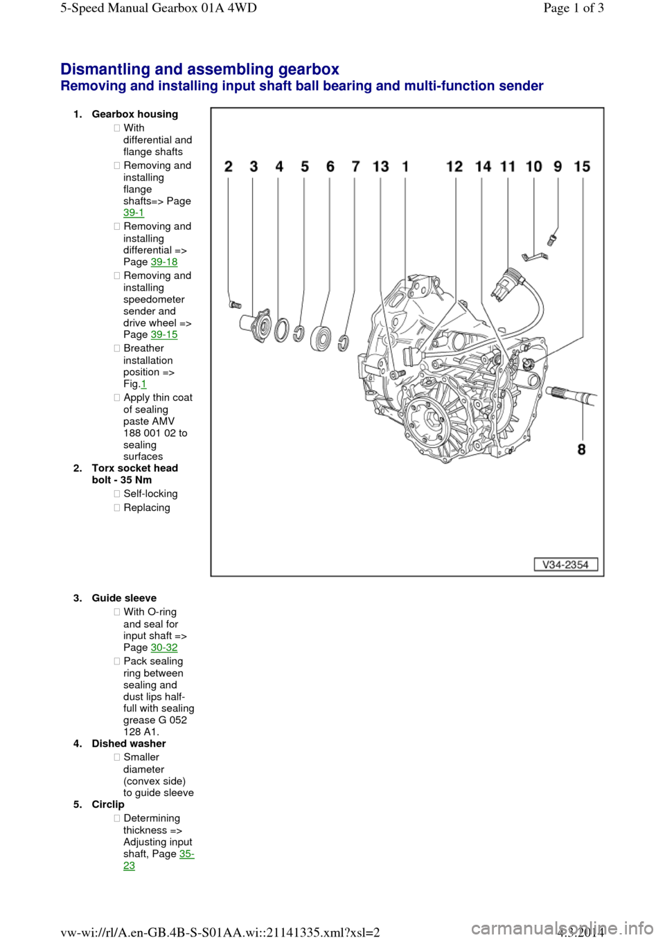
Dismantling and assembling gearbox Removing and installing input shaft ball bearing and multi-function sender 1.Gearbox housing ◆ With differential and flange shafts
◆ Removing and
installing
flange
shafts=> Page
39-1
◆ Removing and
installing
differential =>
Page 39-18
◆ Removing and
installing
speedometer
sender and
drive wheel =>
Page 39-15
◆ Breather
installation
position =>
Fig.1
◆ Apply thin coat of sealing
paste AMV
188 001 02 to
sealing
surfaces
2.Torx socket head
bolt - 35 Nm
◆ Self-locking
◆ Replacing
3.Guide sleeve ◆ With O-ring
and seal for
input shaft =>
Page 30-32
◆ Pack sealing
ring between
sealing and
dust lips half-full with sealing grease G 052
128 A1.
4.Dished washer
◆ Smaller
diameter
(convex side) to guide sleeve 5.Circlip
◆ Determining
thickness => Adjusting input shaft, Page 35-23 Page 1 of 35-Speed Manual Gearbox 01A 4WD4.3.2014vw-wi://rl/A.en-GB.4B-S-S01AA.wi::21141335.xml?xsl=2