change time AUDI A6 2005 C5 / 2.G Electrics System Training Manual
[x] Cancel search | Manufacturer: AUDI, Model Year: 2005, Model line: A6, Model: AUDI A6 2005 C5 / 2.GPages: 92, PDF Size: 4.42 MB
Page 11 of 92
Downloaded from www.Manualslib.com manuals search engine Audi
Audi A6 2005>
2005 (5)
Saloon
BBJ 3.0l Motronic / 160 kW Guided fault-finding
Function/component selection
Selecting a function or component
Electrical system (Rep. Gr. 01; 90 - 97)
01 – Self-diagnosis systems
61 – Battery control
J644 – Control unit for power management, Functions
A – Battery, Charge level
A – Battery, Battery testing
J644 – Power management, General description
J644 – Control unit for power management, Coding
J644 – Read out history data
J644 – Power management, Read measured-value blocks
J644 – Power management, Query fault memory
J644 – Data link tests for generator voltage
J644 – Replace control unit
J644 – Power management, Activate/deactivate Transport mode
Battery change history
Data for the last three battery changes is stored.
Power balance history – driving (= engine on)
The power balance and duration of the last five
journeys are logged.
Power balance history – idle (= engine off)
The power balance and duration of the last five idle
times are logged.
Other data is not relevant for Customer Service.
History dataThe diagnosis tester can be used to read out
data from the control unit for power management,
which makes it much easier to analyse the on-board
power supply and the battery.
Open-circuit voltage history
If the battery open-circuit voltage is less than the
threshold values of 12.5 volts, 12.2 volts and
11.5 volts, an entry is written to the history data.
The last four entries can always be read out.
Voltage measurement starts when
– CAN Convenience is in Sleep mode and
– terminal 15 is switched off for at least 2 hours
and
– the vehicle’s power consumption is < 100 mA.
Voltage measurement ends when
– the voltage increases or
– the current increases or
– the control unit triggers Sleep mode or
– the control unit detects a new battery.
Closed-circuit current history
If the closed-circuit current exceeds the threshold
value of 50 mA, an entry is written to the history
data. The last ten entries can be read out.
Current measurement starts when
– CAN Convenience is in Sleep mode and
– terminal 15 is switched off for at least 2 hours
and
– the vehicle’s power consumption is > 50 mA.
Current measurement ends when
– the current decreases or
– the control unit triggers Sleep mode.
Breakdown analysis
If the control unit for power management detects
the status "Cannot start vehicle", an entry is written
to the history data.
Cut-off level history
Data for the last 15 cut-off levels is stored.
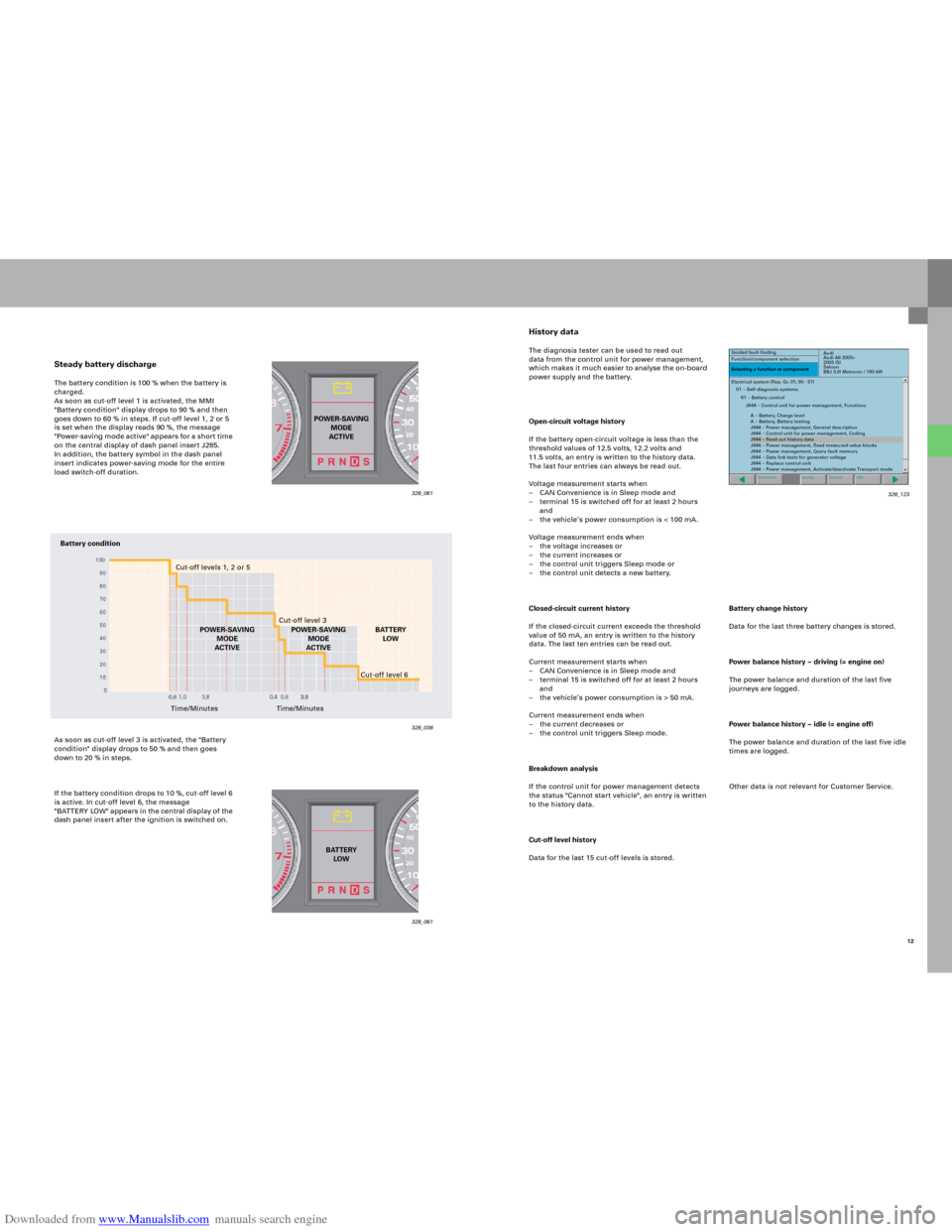
Steady battery dischargeThe battery condition is 100 % when the battery is
charged.
As soon as cut-off level 1 is activated, the MMI
"Battery condition" display drops to 90 % and then
goes down to 60 % in steps. If cut-off level 1, 2 or 5
is set when the display reads 90 %, the message
"Power-saving mode active" app ears fo r a sho r t time
on the central display of dash panel insert J285.
In addition, the battery symbol in the dash panel
insert indicates power-saving mode for the entire
load switch-off duration.
As soon as cut-off level 3 is activated, the "Battery
condition" display drops to 50 % and then goes
down to 20 % in steps.
If the battery condition drops to 10 %, cut-off level 6
is active. In cut-off level 6, the message
"B AT TERY LOW" appears in the central di splay of the
dash panel insert after the ignition is switched on.
326_061 326_061
326_036
POWER-SAVING
MODE
ACTIVE
BATTERY
LOW
Battery condition
Cut-off levels 1, 2 or 5
Cut-off level 3
POWER-SAVING
MODE
ACTIVEBATTERY
LOW
Time/MinutesCut-off level 6
Time/MinutesPOWER-SAVING
MODE
ACTIVE
12 326_123
Page 21 of 92
Downloaded from www.Manualslib.com manuals search engine 23
Vehicl e ke y
The key has a mechanically coded hinged bit for the
lock cylinder in the driver’s door and the tailgate/
boot lid. The transponder function is integrated into
the electronics and also works without a battery.
An integrated battery powers the electronics for the
radio remote control and Advanced Key functions.
A new feature here is the bi-directional data
exchange between the radio-control key and the
control unit for access and start authorisation via
the antenna for central locking and anti-theft
warning system R47. This is used to transfer the
status of the central locking system into the key.
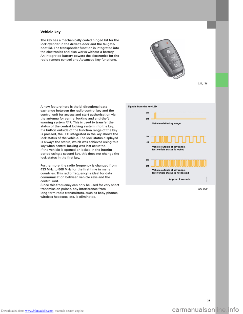
If a button outside of the function range of the key
is pressed, the LED integrated in the key shows the
lock status of the vehicle. The lock status displayed
is always the status, which was achieved using this
key when central locking was last actuated.
If the vehicle is opened or locked in the interim
period using a second key, this does not change the
lock status in the first key.
Furthermore, the radio frequency is changed from
433 MHz to 868 MHz for the first time in many
countries. This radio frequency is ideal for data
communication between vehicle keys and the
control unit.
Since this frequency can only be used for very short
transmission pulses, any interference from
long-term radio transmitters, such as baby phones,
wireless headsets, etc. is eliminated.
326_138
326_058 Vehicle within key range
Vehicle outside of key range,
last vehicle status is locked Signals from the key LED
Vehicle outside of key range,
last vehicle status is not locked
Approx. 4 seconds on
off
on
off
on
off
Page 31 of 92
Downloaded from www.Manualslib.com manuals search engine 33
Bi-xenon headlights
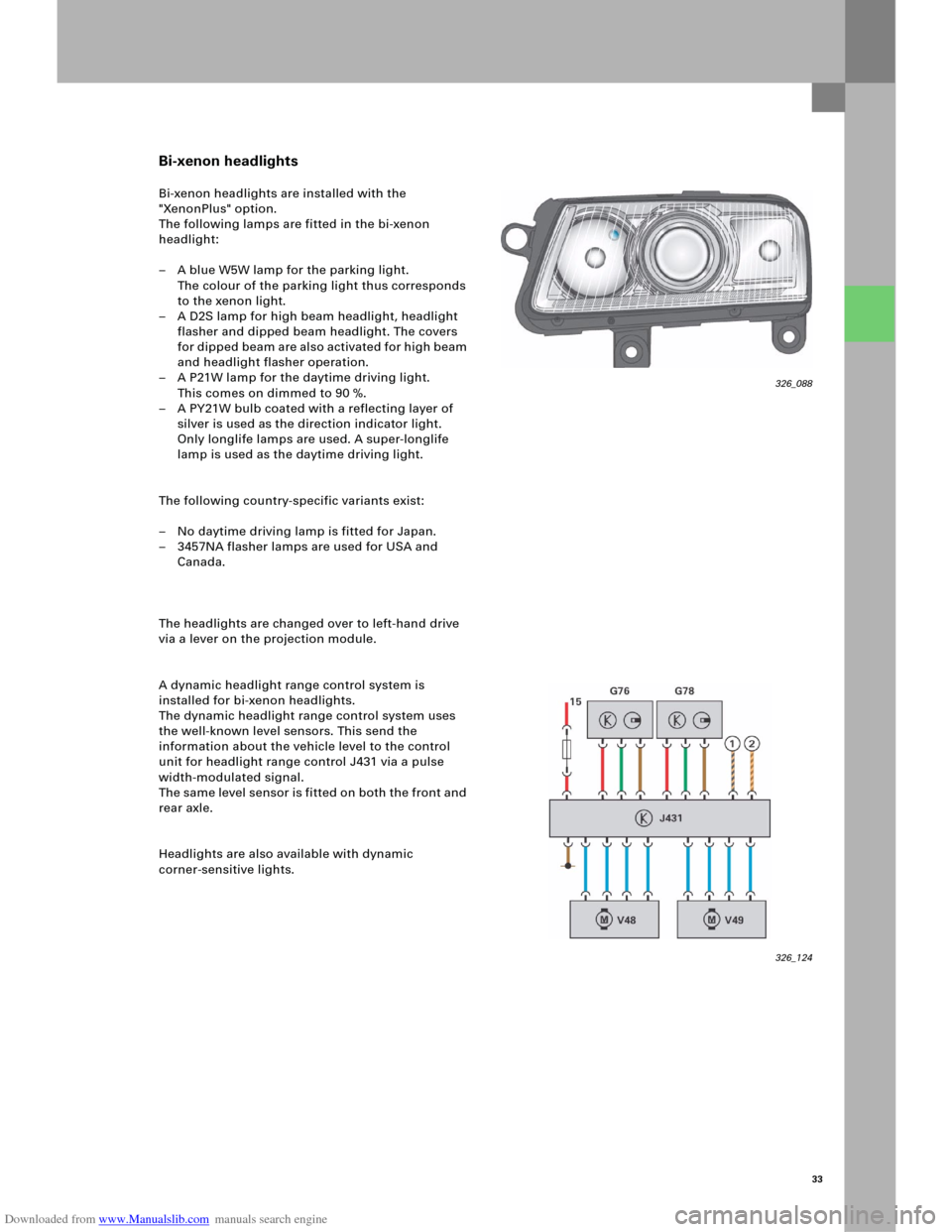
Bi-xenon headlights are installed with the
"XenonPlus" option.
The following lamps are fitted in the bi-xenon
headlight:
– A blue W5W lamp for the parking light.
The colour of the parking light thus corresponds
to the xenon light.
– A D2S lamp for high beam headlight, headlight
flasher and dipped beam headlight. The covers
fo r d i p p ed b e am a re al s o a c t i v at e d fo r h i gh b ea m
and headlight flasher operation.
– A P21W lamp for the daytime driving light.
This comes on dimmed to 90 %.
– A PY21W bulb coated with a reflecting layer of
silver is used as the direction indicator light.
Only longlife lamps are used. A super-longlife
lamp is used as the daytime driving light.
The following country-specific variants exist:
– No daytime driving lamp is fitted for Japan.
– 3457NA flasher lamps are used for USA and
Canada.
The headlights are changed over to left-hand drive
via a lever on the projection module.
A dynamic headlight range control system is
installed for bi-xenon headlights.
The dynamic headlight range control system uses
the well-known level sensors. This send the
information about the vehicle level to the control
unit for headlight range control J431 via a pulse
width-modulated signal.
The same level sensor is fitted on both the front and
rear axle.
Headlights are also available with dynamic
corner-sensitive lights.
326_088
326_124
Page 34 of 92

Downloaded from www.Manualslib.com manuals search engine 36
Signal and data exchange
The same sensors that are used for dynamic
headlight range control for bi-xenon headlights are
also used as level sensors. They send a pulse
width-modulated signal to the control unit for
headlight range control. Data is exchanged between
t h e c o n t ro l u n i t fo r h e ad l i gh t ra n g e c o n tro l J 4 3 1 an d
the power modules in the headlight on the left J667
and right J668 via a 500-kBaud CAN.
Show Room function
The Show Room function can be used to pivot the
headlights by moving the steering wheel – even
when the vehicle is stationary – for presentation.
The function can be adapted using the diagnosis
tester in the control unit for headlight beam
adjustment.
If the vehicle is then driven at more than 30 km/h,
the function is permanently disabled. The function
can be switched on again at any time using the
diagnosis tester.
Convenience electrics
326_074
Audi
Audi A6 2005>
2005 (5)
Saloon
BBJ 3.0l Motronic / 160 kW Guided fault-finding
Function/component selection
Selecting a function or component
Body (Rep. Gr. 01; 50 - 97)
Electrical system (Rep. Gr. 01; 27, 90 - 97)
01 – Self-diagnosis systems
55 – Dynamic headlight range control
J431 – Dynamic headlight range control, Functions
J431 – Contr. unit, head. range control (HRC), General system descr.
J431 – Control unit for headlight range control (HRC), Adaptation
J431 – Contr. unit, head. range control (HRC), Adapt. – Show Room
J431 – Control unit for headlight range control (HRC), Coding
J431 – Control unit for headlight range control (HRC), Replacing
J431 – Control unit for headlight range control (HRC), Basic setting
J431 – Contr. unit, head. range contr. (HRC), Read. meas.-val. blocks
J431 - Contr. unit, head. range control (HRC), selective actuator test
J431 – Contr. unit, head. range contr. (HRC), sequential actuator test
326_085
Page 52 of 92
Downloaded from www.Manualslib.com manuals search engine 54
The tilt sensor for the anti-theft warning system is
integrated directly in control unit 2 for on-board
power supply J520 in the new Audi A6 ‘05.
The fluid-filled sensor registers changes in the
vehicle tilt both transversely and longitudinally,
thereby preventing incorrect triggering as a result of
shaking through viscous fluid and electronic delay.
The current tilt values can be read out using
measured-value blocks.
Diagnosis
– Measured-value blocks
Measured-value blocks are available for the
following functions:
– Servotronic
– Sliding roof
– Tilt angle
–Actuator test
Checks can be carried out for the following
functions, depending on the version:
– Glove compartment release
– Servotronic valve
– Sliding roof activation (can be measured
using a multimeter on the on-board power
supply control unit, sliding roof does not
open, however, if it is not released by the
central control unit for the convenience
system)
–Coding
The High-Line version of control unit 2 for
on-board power supply J520 must be coded for
the following functions:
– Tilt sensor (with or without)
– Sliding roof (with or without)
Convenience electrics
Note
The tilt sensor function can be switched off
using a button in the driver’s door panel.
Reference
For further information on the tilt sensor
function, please refer to the SSP 254,
Audi A4 ‘01 – Technology.
Tilt sensor for anti-theft warning system
Page 67 of 92

Downloaded from www.Manualslib.com manuals search engine 69
MMI Basic
Standard equipment in the new Audi A6 includes
MMI Basic with the MMI operating concept, a
7" monochrome display (J685) in the dash panel
inser t as well as an integrated, analogue radio tuner
and 4x antenna diversity, CD drive and a 2x20-watt
amplifier.
In principle, these drivers are available in all
versions of the control unit for front
information J523.
In the MMI Basic version, the loudspeakers that are
integrated into the front doors are connected
directly to the control unit for front
information J523.
If the Standard Sound System or BOSE option is
installed, this internal amplifier is deactivated via
coding. The loudspeakers are then connected to the
relevant digital sound package control unit J525.Digital tuner technology will be available in the
Audi A6 at a later date. Depending on the market in
question, a satellite radio receiver or a receiver for
terrestrially emitted, but digitally coded
transmissions will then be available.
Legend
The orange symbols represent the possible optional
equipment. If a relevant option is missing, simply
follow the route indicated by arrows to close the
MOST ring.
326_042 Front information
are used
in the tester
J685Multimedia
operating unit
E380Antenna booster
R24Loudspeaker
front
Control unit for front information J523
+ Radio R
+ CD player R89
+ Amplifier R12 (active)Loudspeaker
DSP amplifier
J525
DSP amplifier
BOSE
J525
Loudspeaker
CD changer
R41 Te l e p h o n e
transmitter and
for telephone
R36 Data bus diagnosis
interface
J533Antenna
amplifier 2
R111
Steering column
electronics
J527Multi-function
steering wheel
J453
Page 68 of 92

Downloaded from www.Manualslib.com manuals search engine 70
MMI Basic Plus
As an option, the MMI Basic system can be
equipped with additional functions in the radio and
sound field in the form of a "Plus" version.
This includes, for example, a TP Memo function,
which enables the recording of traffic
announcements for a duration of eight minutes in
total.
A programmable recording period can be used to
provide up-to-date traffic announcements before
starting a journey. Stored traffic messages are
automatically deleted after six hours to ensure that
they are always up-to -date. Instead of the integrated
amplifier, the standard sound system with its own
digital sound package control unit J525 will be used
as standard as of this MMI version.
The internal amplifier can be deactivated via coding
in this and later MMI versions.
Infotainment
Legend
The orange symbols represent the possible optional
equipment. If a relevant option is missing, simply
follow the route indicated by arrows to close the
MOST ring.
326_043 Front information
are used
in the tester
J685Multimedia
operating unit
E380Antenna booster
R24
Control unit for front information J523
+ Radio R
+ CD player R89Loudspeaker
DSP amplifier
J525
DSP amplifier
BOSE
J525
Loudspeaker
Te l e p h o n e
transmitter and
for telephone
R36 Data bus diagnosis
interface
J533CD changer
R41 Antenna
amplifier 2
R111
Reference
Please refer to the Driver’s Manual for
information on operating the enhanced TP
Memo function!
Steering column
electronics
J527Multi-function
steering wheel
J453
Page 69 of 92

Downloaded from www.Manualslib.com manuals search engine 71
MMI Basic Navigation
The MMI Basic Plus is available on request with a
basic navigation function. For this purpose, a
navigation module is integrated into the
information control unit J523. Optical route
guidance is provided on the central display in the
dash panel insert. The destination is entered using
the MMI operating system with its central knob/
pushbutton.
Audible directions for route guidance are also
output via the sound system.
The data required for navigation is read in via the
integrated CD drive.
Legend
The orange symbols represent the possible optional
equipment. If a relevant option is missing, simply
follow the route indicated by arrows to close the
MOST ring.
326_041
Front information
are used
in the tester
J685Multimedia
operating unit
E380Antenna booster
R24Antenna
amplifier 2
R111
Control unit for front information J523
+ Radio
+ Navigation with CD drive J401Loudspeaker
DSP amplifier
J525
Loudspeaker DSP amplifier
BOSE
J525
CD changer
R41 Te l e p h o n e
transmitter and
for telephone
R36 Data bus diagnosis
for data bus
J533Antenna for
Navigation
R50
Steering column
electronics
J527Multi-function
steering wheel
J453
Page 70 of 92

Downloaded from www.Manualslib.com manuals search engine 72
MMI High
The MMI High comes with the 7" colour display.
The standard equipment of the Top system in
Audi A6 ‘05 Infotainment includes an RDS dual-
tuner, the standard sound system and a 6x CD
changer in the glove compartment. As an optional
extra, this MMI version is also available with DVD
navigation, which is already used in the current A8
‘03, as well as the voice operator system with the
voice input control unit J507 as a plug-in module of
the radio module R.
Only in this MMI version can drivers choose
between the fixed telephone module and the mobile
baseplate. The well-known analogue TV tuner R78 is
also available at present as an optional extra.
Infotainment
Legend
The orange symbols represent the possible optional
equipment. If a relevant option is missing, simply
follow the route indicated by arrows to close the
MOST ring.
326_044 Front information
are used
in the tester
J685Multimedia
operating unit
E380
Control unit for front information J523Loudspeaker
DSP amplifier
J525
Loudspeaker DSP amplifier
BOSE
J525
CD changer
R41 Te l e p h o n e
transmitter and
for telephone
R36 TV tuner
R78
Te l e p h o n e /
telematics
J526
Handset
for telephone
R37 Radio
R
Vo ic e i n pu t
J507 Navigation
with CD drive
J401
Reference
Information on the DVD-based navigation
system can be found in the SSP 293,
Audi A8 ´03 – Infotainment.
Antenna booster
R24Antenna
amplifier 2
R111
Data bus diagnosis
interface
J533
Steering column
electronics
J527
Multi-function
steering wheel
J453
Page 75 of 92
Downloaded from www.Manualslib.com manuals search engine 77
The control unit for front information J523 includes
an enhanced TP recording system in the Standard
Plus and Standard Navigation versions. This is a
programmable traffic programme recording
function, which is possible via the MMI operating
system.
Two different start times can be set. The traffic
broadcasts that are received are recorded for a
duration of 2 hours from the relevant start time.
This setting remains unchanged until the timer
function is switched off or the programmed times
are changed. A memory with a recording capacity of
8 minutes is available for the recording. When the
memory is full, the oldest messages are overwritten.
The CD-based navigation function is integrated as
an optional module in the display and operating
unit for front information J523.
If this equipment is installed, the vehicle comes with
the antenna module R50, the antenna for
GPS navigation in the top area of the rear window
(see Chapter Antenna systems). This antenna
delivers the GPS signal. If the mobile baseplate was
also requested, the vehicle has a roof antenna
(antena for radio, telephone, navigation R52), which
supplies the GSM and GPS signal. All other input
signals are only supplied by networking the relevant
control units. Playback of the stored messages can
also be controlled via the MMI. It is possible to
select here whether you want to play the entire
sequence or only one particular message.Functional features of the standard navigation
function:
– Position-finding through interactive destination
entry/selection
– Interactive journey planner/management with
stop-off destinations
– Selection of route options
– Route guidance (acoustic and optical via arrows
in display on dash panel insert J285)
– Dynamic route guidance via RDS TMC and online
data
– Audible navigation directions via digital sound
package control unit J525
– Storage and management of destinations
– Output of position data to the CAN bus
(e.g. for Audi telematics)
– Search for imported destinations from the
address book
Navigation input signals from the vehicle network:
Distance signal from control unit for ABS with
EDL J104, signal from reversing light switch
Output signals to the vehicle network:
GPS time including date, voice output to the
digital sound system control unit J525