AUDI A6 2005 C5 / 2.G Electrics System Training Manual
Manufacturer: AUDI, Model Year: 2005, Model line: A6, Model: AUDI A6 2005 C5 / 2.GPages: 92, PDF Size: 4.42 MB
Page 1 of 92
Downloaded from www.Manualslib.com manuals search engine 326
All rights reserved.
Subject to
technical change.
Copyright
AUDI AG
I/VK-35
[email protected]
Fax +49-841/89-36367
AUDI AG
D-85045 Ingolstadt
Technical release 01/04
Printed in Germany
A04.5S00.09.20
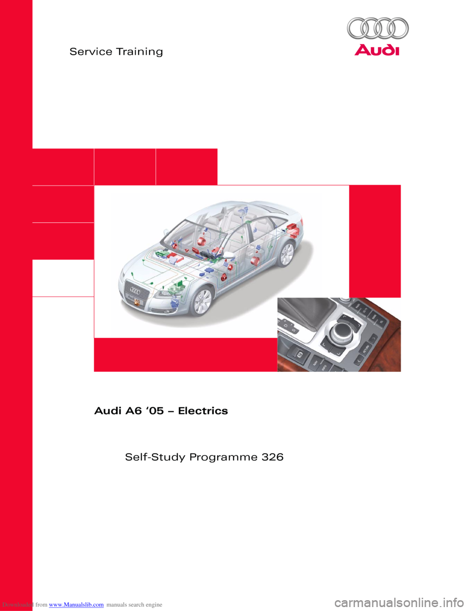
Audi A6 ‘05 – Electrics
Self-Study Programme 326
Vorsprung durch Technik www.audi.co.uk
Service Training
Page 2 of 92
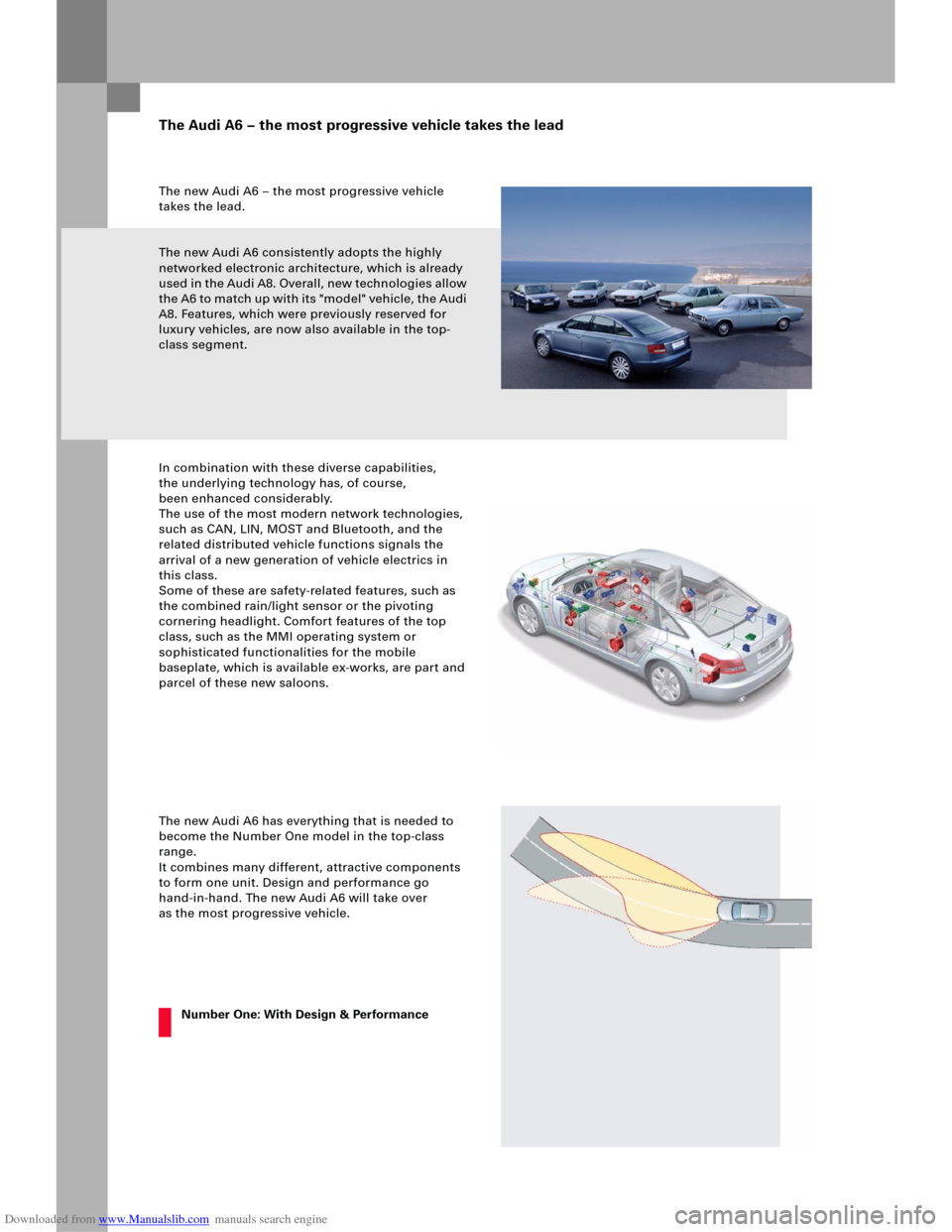
Downloaded from www.Manualslib.com manuals search engine The new Audi A6 – the most progressive vehicle
takes the lead.
The new Audi A6 consistently adopts the highly
networked electronic architecture, which is already
used in the Audi A8. Overall, new technologies allow
the A6 to match up with its "model" vehicle, the Audi
A8. Features, which were previously reserved for
luxury vehicles, are now also available in the top-
class segment.
In combination with these diverse capabilities,
the underlying technology has, of course,
been enhanced considerably.
The use of the most modern network technologies,
such as CAN, LIN, MOST and Bluetooth, and the
related distributed vehicle functions signals the
arrival of a new generation of vehicle electrics in
this class.
Some of these are safety-related features, such as
the combined rain/light sensor or the pivoting
cornering headlight. Comfort features of the top
class, such as the MMI operating system or
sophisticated functionalities for the mobile
baseplate, which is available ex-works, are part and
parcel of these new saloons.
The new Audi A6 has everything that is needed to
become the Number One model in the top-class
range.
It combines many different, attractive components
to form one unit. Design and performance go
hand-in-hand. The new Audi A6 will take over
as the most progressive vehicle.
The Audi A6 – the most progressive vehicle takes the lead
Number One: With Design & Performance
Page 3 of 92
Downloaded from www.Manualslib.com manuals search engine Note ReferenceNote Reference
Control unit installation positions . . . . . . . . . . . . . . . . . . . . . . . . . . . . . . . . . . . . . . . 4
Bus topology . . . . . . . . . . . . . . . . . . . . . . . . . . . . . . . . . . . . . . . . . . . . . . . . . . . . . . . . . . 6
Installation positions of fuses and relays . . . . . . . . . . . . . . . . . . . . . . . . . . . . . . . . . 8
Overview
Convenience electrics
Control unit for power management J644 . . . . . . . . . . . . . . . . . . . . . . . . . . . . . . . 10
Access and start authorisation . . . . . . . . . . . . . . . . . . . . . . . . . . . . . . . . . . . . . . . . . 13
Immobiliser and component protection . . . . . . . . . . . . . . . . . . . . . . . . . . . . . . . . . 30
External lights . . . . . . . . . . . . . . . . . . . . . . . . . . . . . . . . . . . . . . . . . . . . . . . . . . . . . . . . 32
Control unit in dash panel insert J285 . . . . . . . . . . . . . . . . . . . . . . . . . . . . . . . . . . 40
Control unit for on-board power supply J519 . . . . . . . . . . . . . . . . . . . . . . . . . . . . 42
Control unit 2 for on-board power supply J520 . . . . . . . . . . . . . . . . . . . . . . . . . . 52
Central control unit for convenience system J393 . . . . . . . . . . . . . . . . . . . . . . . . 55
Door control units J386 - J389 . . . . . . . . . . . . . . . . . . . . . . . . . . . . . . . . . . . . . . . . . 63
Control units for seat adjustment. . . . . . . . . . . . . . . . . . . . . . . . . . . . . . . . . . . . . . . 65
Infotainment
Multimedia interface . . . . . . . . . . . . . . . . . . . . . . . . . . . . . . . . . . . . . . . . . . . . . . . . . . 68
Antenna systems . . . . . . . . . . . . . . . . . . . . . . . . . . . . . . . . . . . . . . . . . . . . . . . . . . . . . 75
Control unit for front information J523 . . . . . . . . . . . . . . . . . . . . . . . . . . . . . . . . . . 76
Sound systems . . . . . . . . . . . . . . . . . . . . . . . . . . . . . . . . . . . . . . . . . . . . . . . . . . . . . . . 81
Available telephone systems . . . . . . . . . . . . . . . . . . . . . . . . . . . . . . . . . . . . . . . . . . . 86
The Self-Study Programme provides information on the fundamentals of design and function of new vehicle
models, new vehicle components or new technologies.
The Self-Study Programme is not a Workshop Manual!
Specified values serve only to make the information easier to understand and relate to the software version
that was valid at the time the Self-Study Programme (SSP) was created.
For maintenance and repair work, please make sure to use the current technical documentation.
Contents
Page 4 of 92
Downloaded from www.Manualslib.com manuals search engine 4
Overview
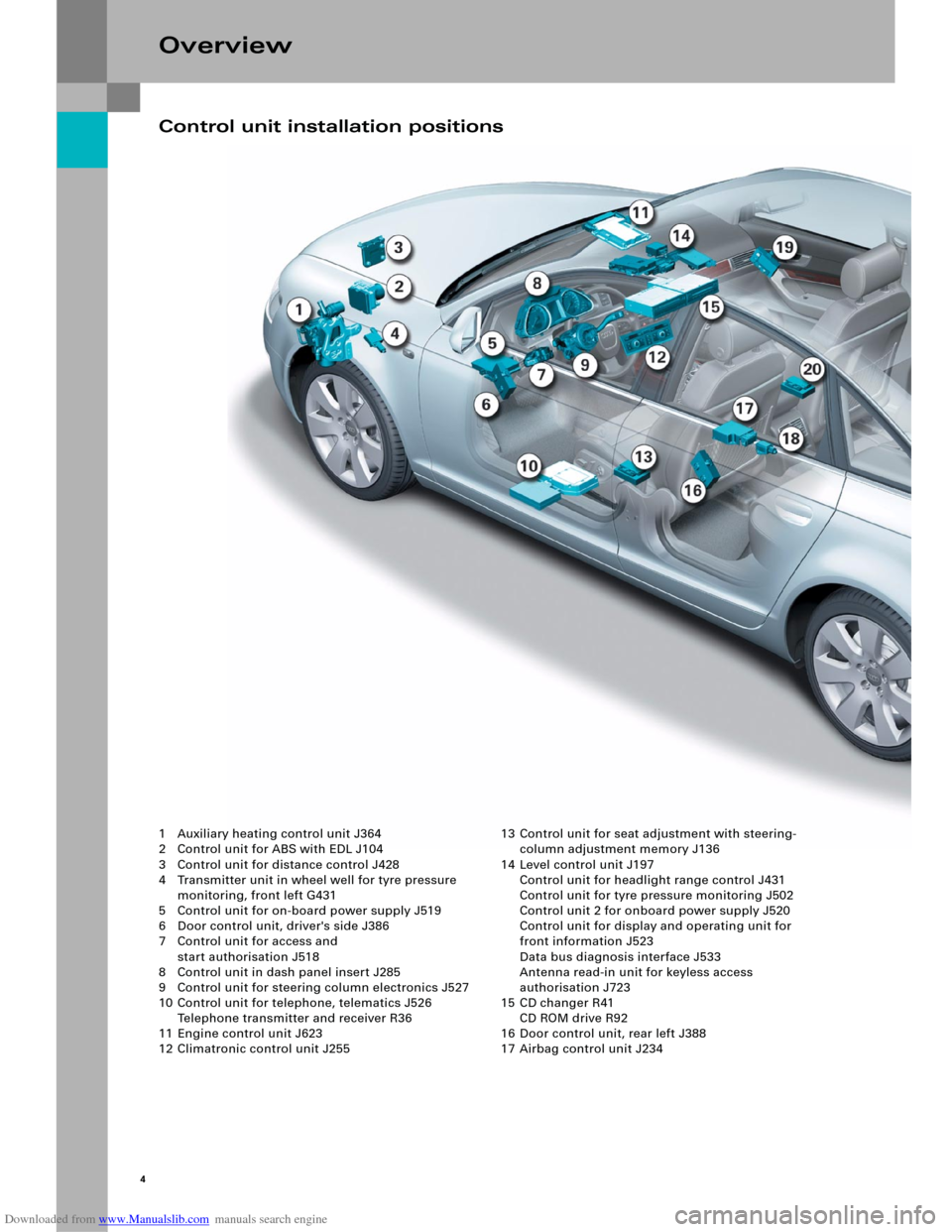
1 Auxiliary heating control unit J364
2 Control unit for ABS with EDL J104
3 Control unit for distance control J428
4 Transmitter unit in wheel well for tyre pressure
monitoring, front left G431
5 Control unit for on-board power supply J519
6 Door control unit, driver's side J386
7 Control unit for access and
start authorisation J518
8 Control unit in dash panel insert J285
9 Control unit for steering column electronics J527
10 Control unit for telephone, telematics J526
Telephone transmitter and receiver R36
11 Engine control unit J623
12 Climatronic control unit J25513 Control unit for seat adjustment with steering-
column adjustment memory J136
14 Level control unit J197
Control unit for headlight range control J431
Control unit for tyre pressure monitoring J502
Control unit 2 for onboard power supply J520
Control unit for display and operating unit for
front information J523
Data bus diagnosis interface J533
Antenna read-in unit for keyless access
authorisation J723
15 CD changer R41
CD ROM drive R92
16 Door control unit, rear left J388
17 Airbag control unit J234
Control unit installation positions
Page 5 of 92
Downloaded from www.Manualslib.com manuals search engine 5
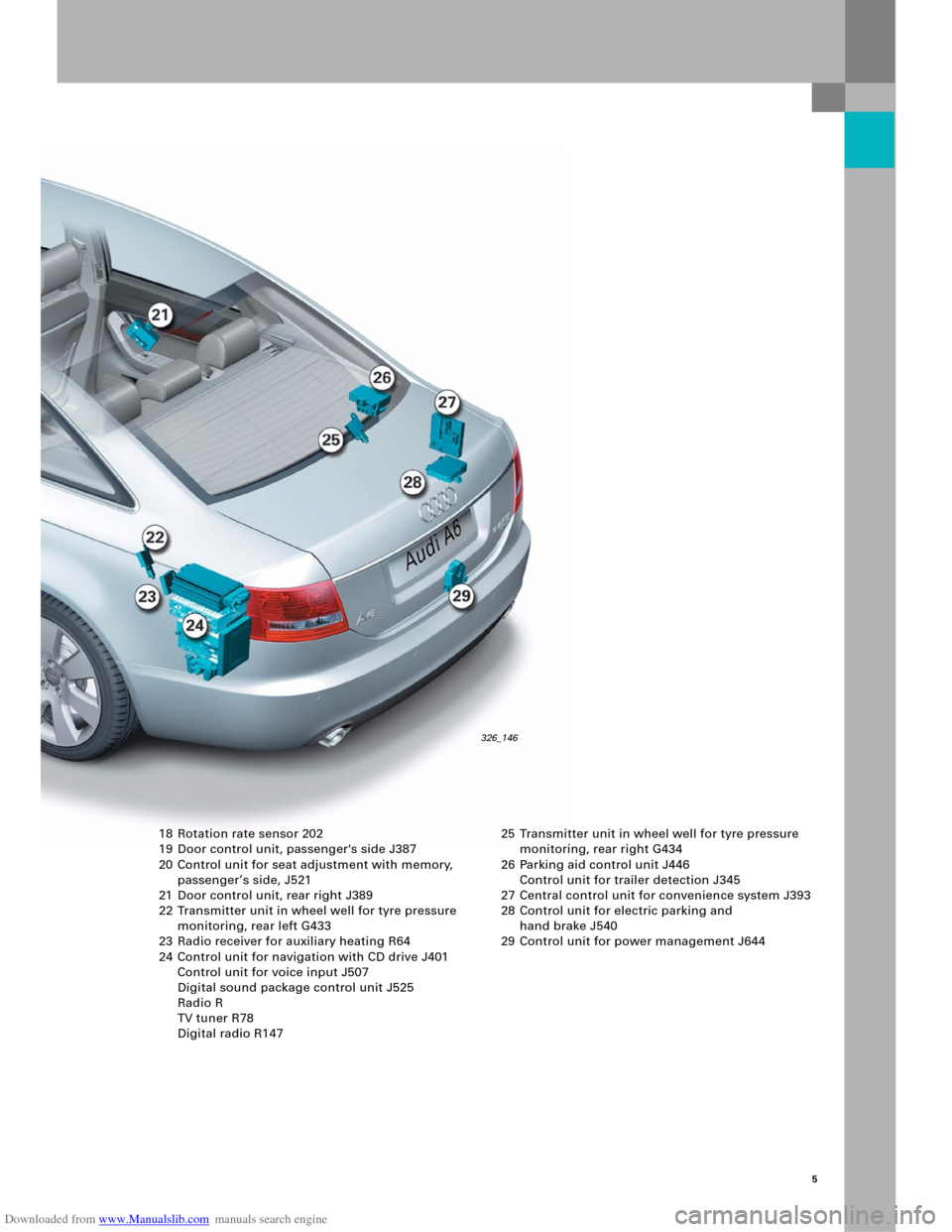
18 Rotation rate sensor 202
19 Door control unit, passenger's side J387
20 Control unit for seat adjustment with memory,
passenger’s side, J521
21 Door control unit, rear right J389
22 Transmitter unit in wheel well for tyre pressure
monitoring, rear left G433
23 Radio receiver for auxiliary heating R64
24 Control unit for navigation with CD drive J401
Control unit for voice input J507
Digital sound package control unit J525
Radio R
TV tuner R78
Digital radio R147 25 Transmitter unit in wheel well for tyre pressure
monitoring, rear right G434
26 Parking aid control unit J446
Control unit for trailer detection J345
27 Central control unit for convenience system J393
28 Control unit for electric parking and
hand brake J540
29 Control unit for power management J644
326_146
Page 6 of 92
Downloaded from www.Manualslib.com manuals search engine 6
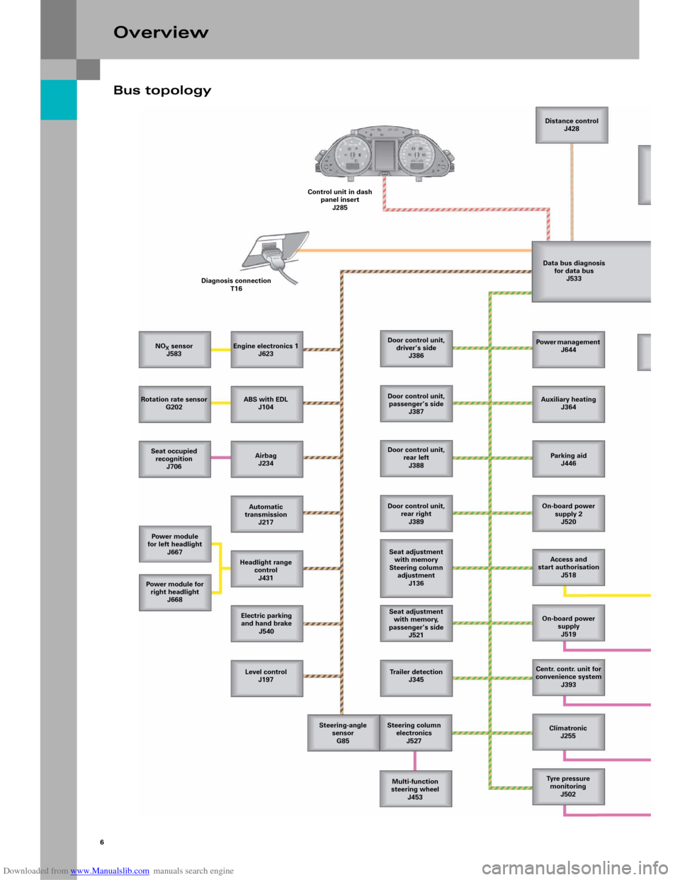
Bus topology
Overview
NOX sensor
J583
Rotation rate sensor
G202
Seat occupied
recognition
J706
Power module
for left headlight
J667
Power m odule for
right headlight
J668
Level control
J197 Electric parking
and hand brake
J540 Headlight range
control
J431 Automatic
transmission
J217 Airbag
J234 ABS with EDL
J104 Engine electronics 1
J623 Diagnosis connection
T16Control unit in dash
panel insert
J285Distance control
J428
Data bus diagnosis
for data bus
J533
Door control unit,
driver’s side
J386
Door control unit,
passenger’s side
J387
Door control unit,
rear left
J388
Door control unit,
rear right
J389
Seat adjustment
with memory
Steering column
adjustment
J136
Seat adjustment
with memory,
passenger’s side
J521
Trailer detection
J345
Steering column
electronics
J527
Multi-function
steering wheel
J453 Steering-angle
sensor
G85Power management
J644
Auxiliary heating
J364
Parking aid
J446
On-board power
supply 2
J520
Access and
start authorisation
J518
On-board power
supply
J519
Centr. contr. unit for
convenience system
J393
Climatronic
J255
Tyre pressure
monitoring
J502
Page 7 of 92
Downloaded from www.Manualslib.com manuals search engine 7
326_027
Display and
operating unit for
front information
J523Te l e p h o n e
transmitter and
for telephone
R36
CD changer
R41
Digital
sound package
J525
Switch for
access and
start authorisation
E415Antenna read-in
unit for keyless access
authorisation
J723
Wiper motor
J400Sensor for rain and
light detection
G397
Passenger
compartment
monitoring
G273Alarm horn
H12
Fresh air fan
J126Refrigerant pressure and
refrigerant temperature
G395
Tr a n s m i t t e r,
front left
G431Tr a n s m i t t e r,
front right
G432Tr a n s m i t t e r,
rear left
G433Transmitter,
rear right
G434Antenna, rear
R96 Te l e p h o n e /
telematics
J526Handset
for telephone
R37
Navigation
with CD drive
J401
TV tuner
R78
Radio module
RVoice input
J507
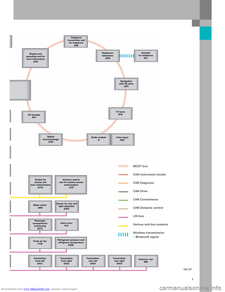
MOST bus
CAN Instrument cluster
CAN Diagnosis
CAN Drive
CAN Convenience
CAN Distance control
LIN bus
Various sub-bus systems
Wireless transmission
– Bluetooth signal
Page 8 of 92

Downloaded from www.Manualslib.com manuals search engine 8
Overview
Installation positions of fuses and relays
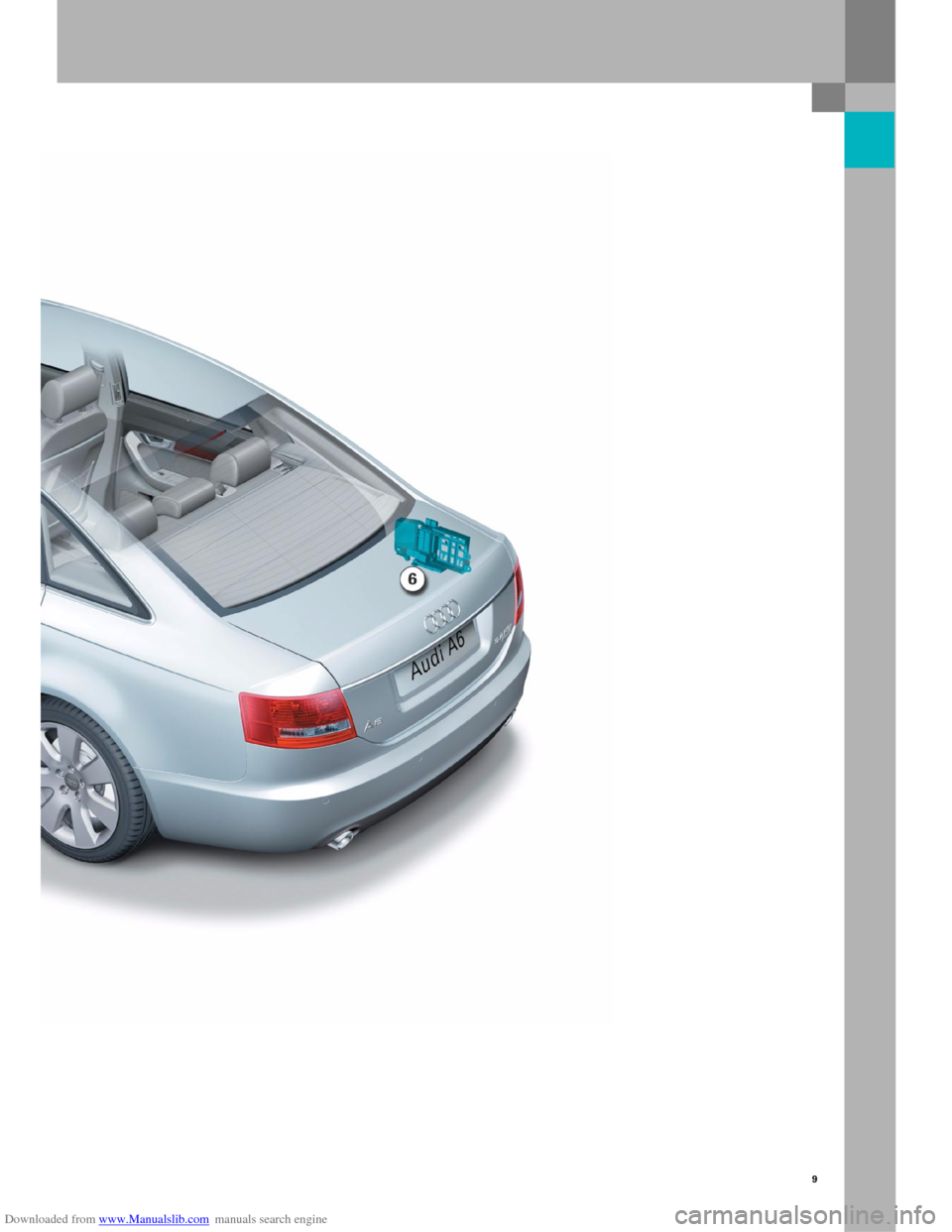
1 E box in radiator tank, left
2 Relay and fuse holder behind
dash panel, left
3 Fuse holder in dash panel, left
4 Main fuse carrier in radiator tank, right
5 Fuse holder in dash panel, right
6 Relay and fuse holder in the boot, right
Page 9 of 92
Downloaded from www.Manualslib.com manuals search engine 9
326_148
Page 10 of 92
Downloaded from www.Manualslib.com manuals search engine 10
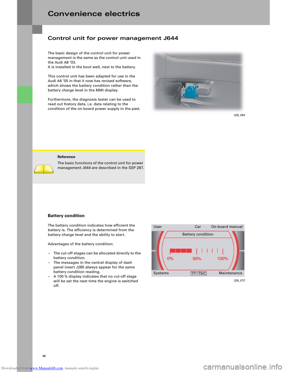
The basic design of the control unit for power
management is the same as the control unit used in
the Audi A8 ‘03.
It is installed in the boot well, next to the battery.
This control unit has been adapted for use in the
Audi A6 ’05 in that it now has revised software,
which shows the battery condition rather than the
battery charge level in the MMI display.
Furthermore, the diagnosis tester can be used to
read out history data, i.e. data relating to the
condition of the on-board power supply in the past.
Convenience electrics
Reference
The basic functions of the control unit for power
management J644 are described in the SSP 287.
Battery condition
The battery condition indicates how efficient the
battery is. The efficiency is determined from the
battery charge level and the ability to start.
Advantages of the battery condition:
– The cut-off stages can be allocated directly to the
battery condition.
– The messages in the central display of dash
panel insert J285 always appear for the same
battery condition reading.
– A 100 % display indicates that no cut-off stage
will be set the next time the engine is switched
off.
326_072
User Car On-board manual
Battery condition
Systems Maintenance
Control unit for power management J644
326_094