display AUDI A6 2005 C5 / 2.G Electrics System Training Manual
[x] Cancel search | Manufacturer: AUDI, Model Year: 2005, Model line: A6, Model: AUDI A6 2005 C5 / 2.GPages: 92, PDF Size: 4.42 MB
Page 4 of 92
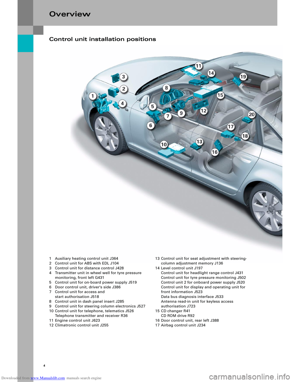
Downloaded from www.Manualslib.com manuals search engine 4
Overview
1 Auxiliary heating control unit J364
2 Control unit for ABS with EDL J104
3 Control unit for distance control J428
4 Transmitter unit in wheel well for tyre pressure
monitoring, front left G431
5 Control unit for on-board power supply J519
6 Door control unit, driver's side J386
7 Control unit for access and
start authorisation J518
8 Control unit in dash panel insert J285
9 Control unit for steering column electronics J527
10 Control unit for telephone, telematics J526
Telephone transmitter and receiver R36
11 Engine control unit J623
12 Climatronic control unit J25513 Control unit for seat adjustment with steering-
column adjustment memory J136
14 Level control unit J197
Control unit for headlight range control J431
Control unit for tyre pressure monitoring J502
Control unit 2 for onboard power supply J520
Control unit for display and operating unit for
front information J523
Data bus diagnosis interface J533
Antenna read-in unit for keyless access
authorisation J723
15 CD changer R41
CD ROM drive R92
16 Door control unit, rear left J388
17 Airbag control unit J234
Control unit installation positions
Page 7 of 92
Downloaded from www.Manualslib.com manuals search engine 7
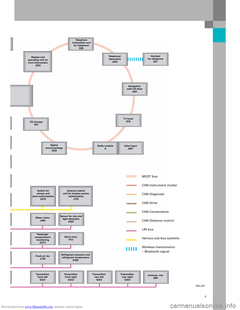
326_027
Display and
operating unit for
front information
J523Te l e p h o n e
transmitter and
for telephone
R36
CD changer
R41
Digital
sound package
J525
Switch for
access and
start authorisation
E415Antenna read-in
unit for keyless access
authorisation
J723
Wiper motor
J400Sensor for rain and
light detection
G397
Passenger
compartment
monitoring
G273Alarm horn
H12
Fresh air fan
J126Refrigerant pressure and
refrigerant temperature
G395
Tr a n s m i t t e r,
front left
G431Tr a n s m i t t e r,
front right
G432Tr a n s m i t t e r,
rear left
G433Transmitter,
rear right
G434Antenna, rear
R96 Te l e p h o n e /
telematics
J526Handset
for telephone
R37
Navigation
with CD drive
J401
TV tuner
R78
Radio module
RVoice input
J507
MOST bus
CAN Instrument cluster
CAN Diagnosis
CAN Drive
CAN Convenience
CAN Distance control
LIN bus
Various sub-bus systems
Wireless transmission
– Bluetooth signal
Page 10 of 92
Downloaded from www.Manualslib.com manuals search engine 10
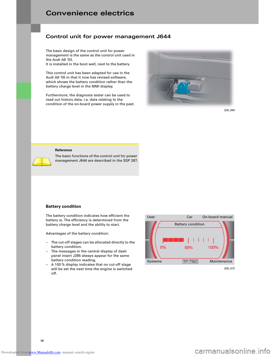
The basic design of the control unit for power
management is the same as the control unit used in
the Audi A8 ‘03.
It is installed in the boot well, next to the battery.
This control unit has been adapted for use in the
Audi A6 ’05 in that it now has revised software,
which shows the battery condition rather than the
battery charge level in the MMI display.
Furthermore, the diagnosis tester can be used to
read out history data, i.e. data relating to the
condition of the on-board power supply in the past.
Convenience electrics
Reference
The basic functions of the control unit for power
management J644 are described in the SSP 287.
Battery condition
The battery condition indicates how efficient the
battery is. The efficiency is determined from the
battery charge level and the ability to start.
Advantages of the battery condition:
– The cut-off stages can be allocated directly to the
battery condition.
– The messages in the central display of dash
panel insert J285 always appear for the same
battery condition reading.
– A 100 % display indicates that no cut-off stage
will be set the next time the engine is switched
off.
326_072
User Car On-board manual
Battery condition
Systems Maintenance
Control unit for power management J644
326_094
Page 11 of 92
Downloaded from www.Manualslib.com manuals search engine Audi
Audi A6 2005>
2005 (5)
Saloon
BBJ 3.0l Motronic / 160 kW Guided fault-finding
Function/component selection
Selecting a function or component
Electrical system (Rep. Gr. 01; 90 - 97)
01 – Self-diagnosis systems
61 – Battery control
J644 – Control unit for power management, Functions
A – Battery, Charge level
A – Battery, Battery testing
J644 – Power management, General description
J644 – Control unit for power management, Coding
J644 – Read out history data
J644 – Power management, Read measured-value blocks
J644 – Power management, Query fault memory
J644 – Data link tests for generator voltage
J644 – Replace control unit
J644 – Power management, Activate/deactivate Transport mode
Battery change history
Data for the last three battery changes is stored.
Power balance history – driving (= engine on)
The power balance and duration of the last five
journeys are logged.
Power balance history – idle (= engine off)
The power balance and duration of the last five idle
times are logged.
Other data is not relevant for Customer Service.
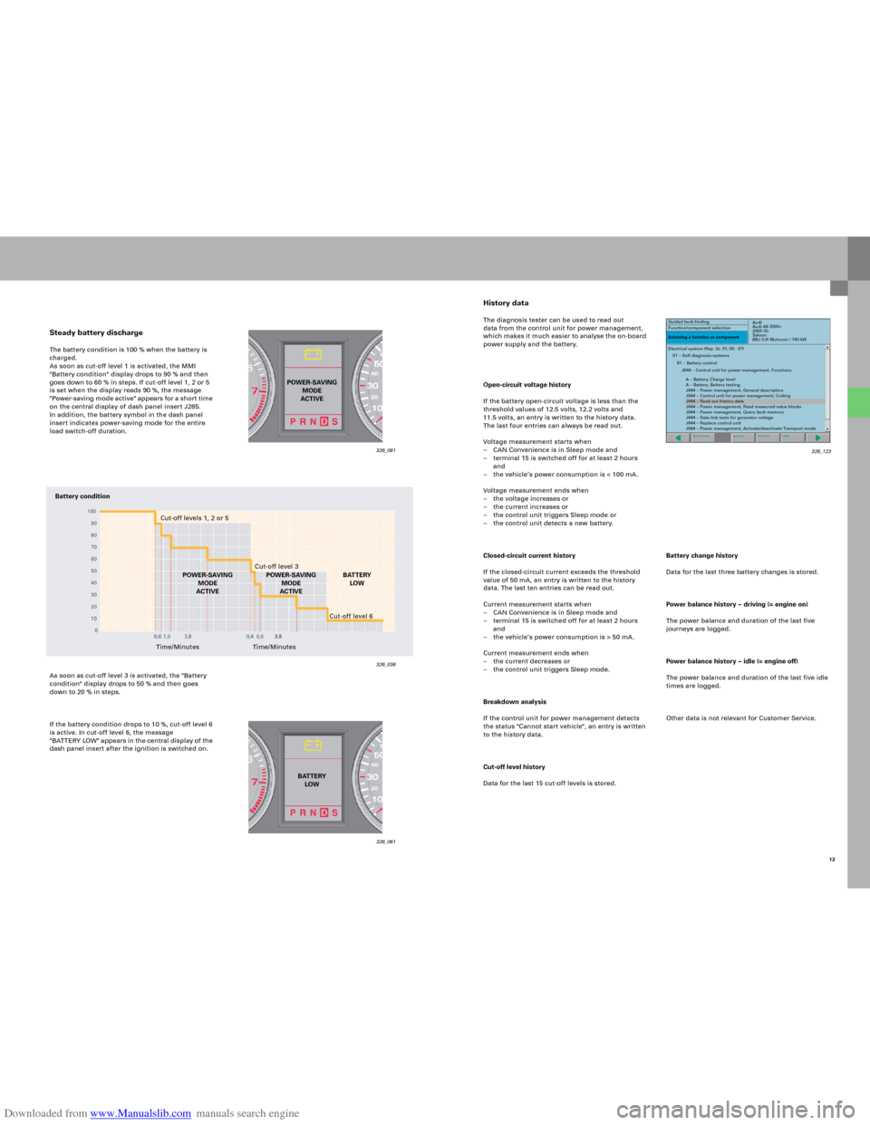
History dataThe diagnosis tester can be used to read out
data from the control unit for power management,
which makes it much easier to analyse the on-board
power supply and the battery.
Open-circuit voltage history
If the battery open-circuit voltage is less than the
threshold values of 12.5 volts, 12.2 volts and
11.5 volts, an entry is written to the history data.
The last four entries can always be read out.
Voltage measurement starts when
– CAN Convenience is in Sleep mode and
– terminal 15 is switched off for at least 2 hours
and
– the vehicle’s power consumption is < 100 mA.
Voltage measurement ends when
– the voltage increases or
– the current increases or
– the control unit triggers Sleep mode or
– the control unit detects a new battery.
Closed-circuit current history
If the closed-circuit current exceeds the threshold
value of 50 mA, an entry is written to the history
data. The last ten entries can be read out.
Current measurement starts when
– CAN Convenience is in Sleep mode and
– terminal 15 is switched off for at least 2 hours
and
– the vehicle’s power consumption is > 50 mA.
Current measurement ends when
– the current decreases or
– the control unit triggers Sleep mode.
Breakdown analysis
If the control unit for power management detects
the status "Cannot start vehicle", an entry is written
to the history data.
Cut-off level history
Data for the last 15 cut-off levels is stored.
Steady battery dischargeThe battery condition is 100 % when the battery is
charged.
As soon as cut-off level 1 is activated, the MMI
"Battery condition" display drops to 90 % and then
goes down to 60 % in steps. If cut-off level 1, 2 or 5
is set when the display reads 90 %, the message
"Power-saving mode active" app ears fo r a sho r t time
on the central display of dash panel insert J285.
In addition, the battery symbol in the dash panel
insert indicates power-saving mode for the entire
load switch-off duration.
As soon as cut-off level 3 is activated, the "Battery
condition" display drops to 50 % and then goes
down to 20 % in steps.
If the battery condition drops to 10 %, cut-off level 6
is active. In cut-off level 6, the message
"B AT TERY LOW" appears in the central di splay of the
dash panel insert after the ignition is switched on.
326_061 326_061
326_036
POWER-SAVING
MODE
ACTIVE
BATTERY
LOW
Battery condition
Cut-off levels 1, 2 or 5
Cut-off level 3
POWER-SAVING
MODE
ACTIVEBATTERY
LOW
Time/MinutesCut-off level 6
Time/MinutesPOWER-SAVING
MODE
ACTIVE
12 326_123
Page 20 of 92

Downloaded from www.Manualslib.com manuals search engine 22
– CAN Communication:
The control unit is a participant on
CAN Convenience. Data exchange between all
the components of the access and start
authorisation system is performed via the
control unit.
It is also the diagnosis interface for the
components involved. All data, e.g. code,
immobiliser data, etc. is stored in the control unit
for access and start authorisation.
– Reading in the P/N signal from the control unit
for automatic transmission J217:
The signal is used to activate the displays
relating to engine start in dash panel insert J285.
Convenience electrics
326_062326_063
SELECT
N OR P
TO START
THE ENGINE SELECT
N OR P
START THE
ENGINE
Page 21 of 92
Downloaded from www.Manualslib.com manuals search engine 23
Vehicl e ke y
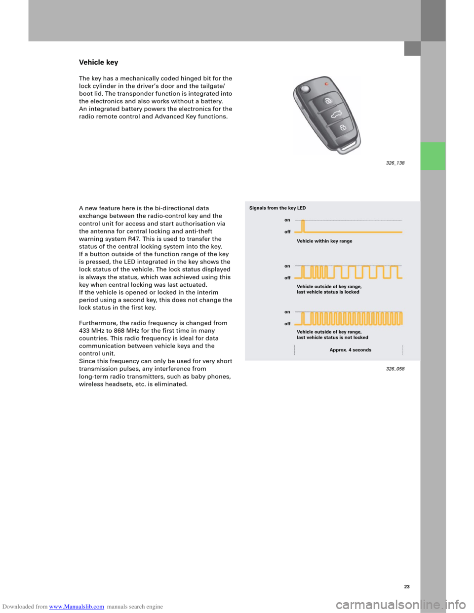
The key has a mechanically coded hinged bit for the
lock cylinder in the driver’s door and the tailgate/
boot lid. The transponder function is integrated into
the electronics and also works without a battery.
An integrated battery powers the electronics for the
radio remote control and Advanced Key functions.
A new feature here is the bi-directional data
exchange between the radio-control key and the
control unit for access and start authorisation via
the antenna for central locking and anti-theft
warning system R47. This is used to transfer the
status of the central locking system into the key.
If a button outside of the function range of the key
is pressed, the LED integrated in the key shows the
lock status of the vehicle. The lock status displayed
is always the status, which was achieved using this
key when central locking was last actuated.
If the vehicle is opened or locked in the interim
period using a second key, this does not change the
lock status in the first key.
Furthermore, the radio frequency is changed from
433 MHz to 868 MHz for the first time in many
countries. This radio frequency is ideal for data
communication between vehicle keys and the
control unit.
Since this frequency can only be used for very short
transmission pulses, any interference from
long-term radio transmitters, such as baby phones,
wireless headsets, etc. is eliminated.
326_138
326_058 Vehicle within key range
Vehicle outside of key range,
last vehicle status is locked Signals from the key LED
Vehicle outside of key range,
last vehicle status is not locked
Approx. 4 seconds on
off
on
off
on
off
Page 29 of 92

Downloaded from www.Manualslib.com manuals search engine 31
New identity
As is already the case with the Audi A8 ‘03 , if a
control unit is stolen, it is no longer necessary
(for safety reasons) to also replace the remaining
control units, which are integrated in the
immobiliser.
In this case, the "New Identity" function must be
used for the control unit for access and start
authorisation and the engine control unit.
It is only a matter of installing a new lock set before
using the "New Identity" function.
The switch for access and start authorisation E415
reads in the key code in electronic form only.
The hinged bit coding is not evaluated signal.
The ignition switch is not par t of the lock set for this
reason.
Component protection
As is already the case with the Audi A8 ’03, the
Convenience and Infotainment control units are also
integrated within the "Component protection" safety
system.
As a result, these control units must be adapted to
the specific vehicle once they have been installed.
The data bus diagnosis interface is integrated into
the "Component protection" function for the first
time. Since component protection works via a
number of control units, the Startup menu in
"Guided fault-finding" is not assigned to any one
control unit and can be found directly under the
self-diagnosis systems.
326_122 326_075
Audi
Audi A6 2005>
2005 (5)
Saloon
BBJ 3.0l Motronic / 160 kW Guided fault-finding
Function test
Teaching driving authorisation
systems
Te s t i n g q u e r y
The following options are available:
1. Adapt the driving authorisation system to suit
the existing immobiliser
2. Assign a new identity to the immobiliser and
re-teach the components
3. Terminate the function test
326_074
Audi
Audi A6 2005>
2005 (5)
Saloon
BBJ 3.0l Motronic / 160 kW Guided fault-finding
Function/component selection
Selecting a function or component
Body (Rep. Gr. 01; 50 - 97)
Electrical system (Rep. Gr. 01; 27, 90 - 97)
Component protection functions
13 – Distance control, Component protection
05 – Access and start authorisation, Component protection
15 – Airbag, Component protection
06 – Seat adjust. with memory, front pass. side, Comp. protection
36 – Seat adjust. with memory, front driver’s side, Comp. protect.
46 – Central module for convenience system, Comp. protection
66 – Seat adjustment with memory, rear, Component protection
07 – Display/operator unit, front, Component protection
17 – Dash panel insert, Component protection
27 – Display/operating unit, rear, Component protection
Switch for access and start authorisation E415
Page 33 of 92
Downloaded from www.Manualslib.com manuals search engine 35
Internal structure
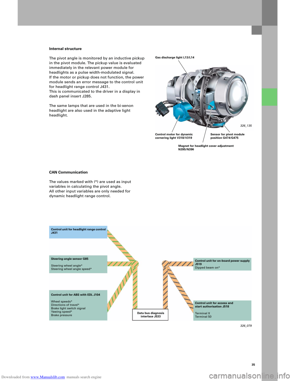
The pivot angle is monitored by an inductive pickup
in the pivot module. The pickup value is evaluated
immediately in the relevant power module for
headlights as a pulse width-modulated signal.
If the motor or pickup does not function, the power
module sends an error message to the control unit
for headlight range control J431.
This is communicated to the driver in a display in
dash panel insert J285.
The same lamps that are used in the bi-xenon
headlight are also used in the adaptive light
headlight.
CAN Communication
The values marked with (*) are used as input
variables in calculating the pivot angle.
All other input variables are only needed for
dynamic headlight range control.
326_079 Data bus diagnosis
interface J533 Co n t ro l u n it fo r h e a d li g h t ra n g e c o n t ro l
J431
Steering-angle sensor G85
Steering wheel angle*
Steering wheel angle speed*
Control unit for ABS with EDL J104
Wheel speeds*
Directions of travel*
Brake light switch signal
Yawing speed*
Brake pressureControl unit for on-board power supply
J519
Dipped beam on*
Control unit for access and
start authorisation J518
Te r m i n a l X
Te r m i n a l 5 0
Gas discharge light L13/L14
326_135
Control motor for dynamic
cornering light V318/V319
Magnet for headlight cover adjustment
N395/N396Sensor for pivot module
position G474/G475
Page 38 of 92
Downloaded from www.Manualslib.com manuals search engine 40
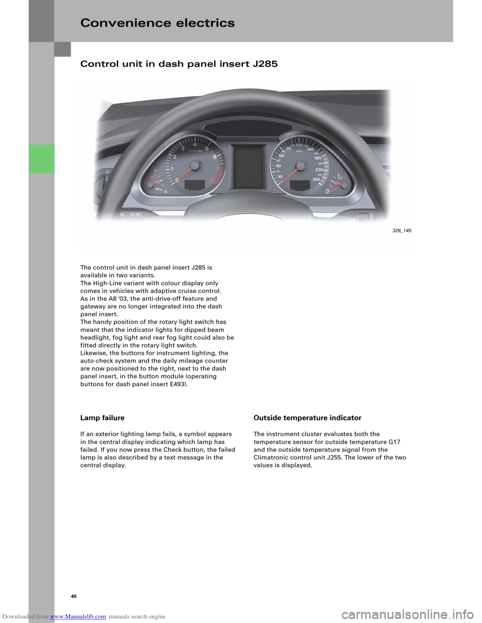
The control unit in dash panel insert J285 is
available in two variants.
The High-Line variant with colour display only
comes in vehicles with adaptive cruise control.
As in the A8 '03, the anti-drive-off feature and
gateway are no longer integrated into the dash
panel insert.
The handy position of the rotary light switch has
meant that the indicator lights for dipped beam
headlight, fog light and rear fog light could also be
fitted directly in the rotary light switch.
Likewise, the buttons for instrument lighting, the
auto-check system and the daily mileage counter
are now positioned to the right, next to the dash
panel insert, in the button module (operating
buttons for dash panel insert E493).
Convenience electrics
Lamp failure
If an exterior lighting lamp fails, a symbol appears
in the central display indicating which lamp has
failed. If you now press the Check button, the failed
lamp is also described by a text message in the
central display.
Outside temperature indicator
The instrument cluster evaluates both the
temperature sensor for outside temperature G17
and the outside temperature signal from the
Climatronic control unit J255. The lower of the two
values is displayed.
Control unit in dash panel insert J285
326_145
Page 39 of 92
Downloaded from www.Manualslib.com manuals search engine 41
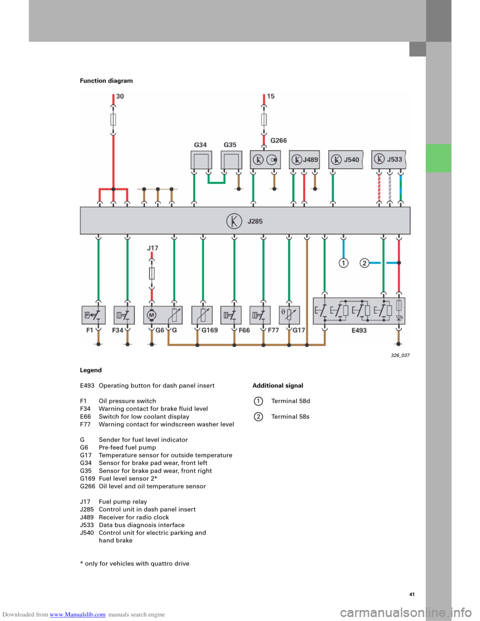
Function diagram
Legend
E493 Operating button for dash panel insert
F1 Oil pressure switch
F34 Warning contact for brake fluid level
E66 Switch for low coolant display
F77 Warning contact for windscreen washer level
G Sender for fuel level indicator
G6 Pre-feed fuel pump
G17 Temperature sensor for outside temperature
G34 Sensor for brake pad wear, front left
G35 Sensor for brake pad wear, front right
G169 Fuel level sensor 2*
G266 Oil level and oil temperature sensor
J17 Fuel pump relay
J285 Control unit in dash panel insert
J489 Receiver for radio clock
J533 Data bus diagnosis interface
J540 Control unit for electric parking and
hand brake
* only for vehicles with quattro drive
326_037
Additional signal
1 Terminal 58d
2 Terminal 58s