fog light AUDI A6 2005 C5 / 2.G Electrics System Training Manual
[x] Cancel search | Manufacturer: AUDI, Model Year: 2005, Model line: A6, Model: AUDI A6 2005 C5 / 2.GPages: 92, PDF Size: 4.42 MB
Page 30 of 92

Downloaded from www.Manualslib.com manuals search engine 32
External lights
Front headlights
Three different front headlights are used in the
Audi A6 ’05:
– Halogen headlights
–Bi-xenon headlights
–Adaptive light
Halogen headlights
Halogen headlights come as standard.
The following lamps are fitted in the halogen on the
vehicle equipment:
– W5W lamp for parking light
– H1 lamp for high beam headlight and headlight
flasher
– H7 lamp for dipped beam headlight and dimmed
as a daytime driving light
– An orange PY21W bulb as the direction indicator
light
The daytime driving light in the halogen headlight is
only available for Canada and the Northern
countries (Scandinavia). It is active when
terminal 15 is switched on and the parking light or
dipped beam light is off.
The following country-specific variants exist:
– The daytime driving light is part of the fog lights
for Canada and
– 3457NA flasher lamps are used for USA and
Canada.
A manual headlight range control system – with
potentiometer – is installed for halogen headlights.
Convenience electrics
326_087
326_149
12 3 4 5
1W5W lamp
2H1 lamp
3H7 lamp
4 PY21W lamp
5D2S lamp
Page 35 of 92
Downloaded from www.Manualslib.com manuals search engine 37
Back lights
Different tail lights are used in the Audi A6 ’05,
depending on the equipment variant.
This is differentiated into the following:
–Basic variant ECE
–High variant ECE
–High variant SAE
Basic variant ECE
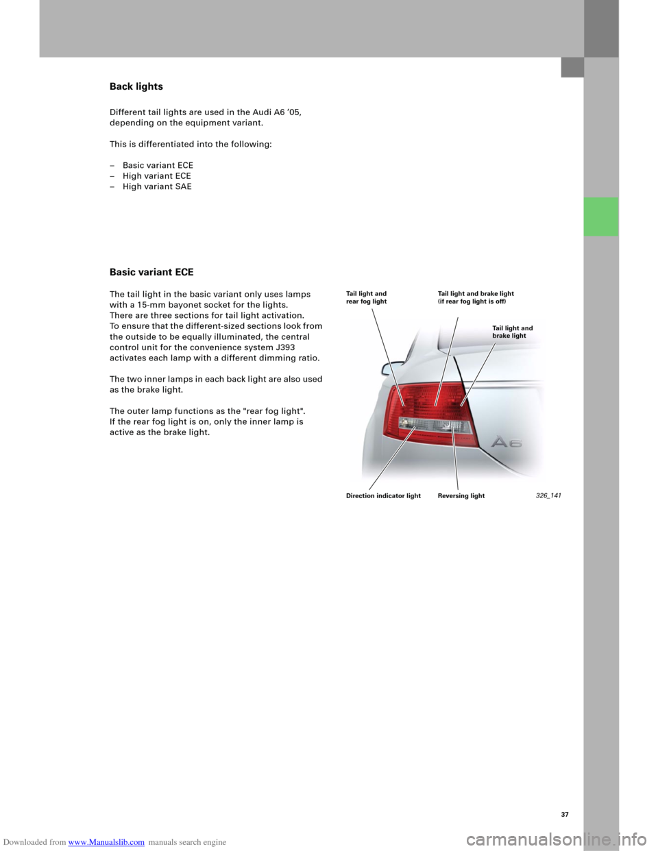
The tail light in the basic variant only uses lamps
with a 15-mm bayonet socket for the lights.
There are three sections for tail light activation.
To ensure that the different-sized sections look from
the outside to be equally illuminated, the central
control unit for the convenience system J393
activates each lamp with a different dimming ratio.
The two inner lamps in each back light are also used
as the brake light.
The outer lamp functions as the "rear fog light".
Ifthe rear fog light is on, only the inner lamp is
active as the brake light.
326_141 Tail light and
rear fog lightTail light and brake light
(if rear fog light is off)
Tail light and
brake light
Direction indicator light Reversing light
Page 36 of 92

Downloaded from www.Manualslib.com manuals search engine 38
High variant ECE
These back lights are installed if bi-xenon headlights
at least are fitted as the front headlights.
The external feature of the High back lights is the
use of LEDs for the brake light.
The LEDs, which are fixed in the reflector housing,
are activated by two contacts from the lamp
bracket.
The rear fog light is located at the bottom of the
back light. Here, the lamp on the driver’s side is
used as the rear fog light, while the lamp on the
passenger’s side serves as the reversing light.
This means that the same lamp bracket can be used
for both the High back light and the Basic back light.
Convenience electrics
326_152 Direction
indicator light
Rear fog light Brake light
Tail lights
Direction
indicator
light
Reversing lightBrake light
Tail lights
Page 37 of 92

Downloaded from www.Manualslib.com manuals search engine 39
High variant SAE
The back lights for the North American market have
standard LED units. The LED units are used for the
indicator and brake light function.
The three sections underneath are for the tail light
lamps.
The S AE back lights have tw o rear fog lights and tw o
reversing lights.
LED unit diagnosis
The failure of an LED is detected by the electronics
in the lamp housing. All LEDs are then switched off
so that the central control unit for the convenience
system J393 can set the relevant fault memory
entry.
326_142 Brake light and
direction indicator lightTail lights
Rear fog light Reversing light
Page 38 of 92
Downloaded from www.Manualslib.com manuals search engine 40
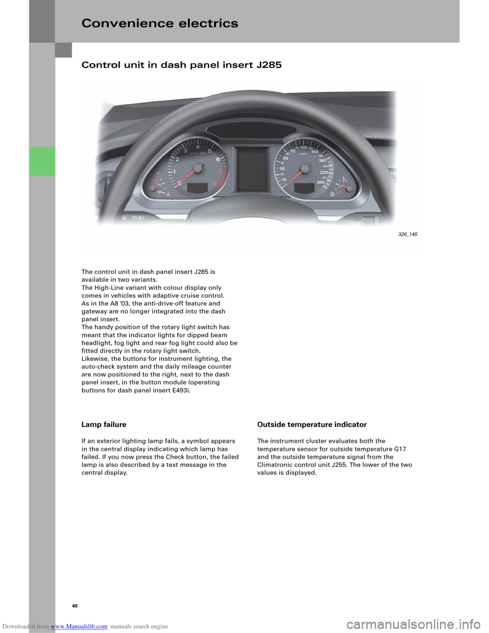
The control unit in dash panel insert J285 is
available in two variants.
The High-Line variant with colour display only
comes in vehicles with adaptive cruise control.
As in the A8 '03, the anti-drive-off feature and
gateway are no longer integrated into the dash
panel insert.
The handy position of the rotary light switch has
meant that the indicator lights for dipped beam
headlight, fog light and rear fog light could also be
fitted directly in the rotary light switch.
Likewise, the buttons for instrument lighting, the
auto-check system and the daily mileage counter
are now positioned to the right, next to the dash
panel insert, in the button module (operating
buttons for dash panel insert E493).
Convenience electrics
Lamp failure
If an exterior lighting lamp fails, a symbol appears
in the central display indicating which lamp has
failed. If you now press the Check button, the failed
lamp is also described by a text message in the
central display.
Outside temperature indicator
The instrument cluster evaluates both the
temperature sensor for outside temperature G17
and the outside temperature signal from the
Climatronic control unit J255. The lower of the two
values is displayed.
Control unit in dash panel insert J285
326_145
Page 42 of 92

Downloaded from www.Manualslib.com manuals search engine 44
Function diagram
Convenience electrics
E1 Light switch
E3 Hazard warning light switch
E7 Fog light switch
E18 Switch for rear fog light
F4 Reversing light switch
F266 Contact switch for bonnet
G357 Sender for vertical steering column adjustm.
G358 Sender for axial steering column adjustment
G397 Sensor for rain and light detection
G474 Sensor for pivot module position, left
G475 Sensor for pivot module position, right
H2 High-pitch horn
H7 Low-pitch horn
J4 Relay for dual-pitch horn
J400 Control unit for wiper motor
J431 Control unit for headlight range control
J519 Control unit for on-board power supply
J667 Power module for left headlight
J668 Power module for right headlightK4 Indicator light for parking light
K6 Indicator light for hazard warning lights
K13 Indicator light for rear fog light
K17 Indicator light for fog lights
L9 Lamp for light-switch lighting
L13 Gas discharge light, left
L14 Gas discharge light, right
L22 Lamp for left fog light
L23 Lamp for right fog light
L174 Lamp for daytime driving light, left
L175 Lamp for daytime driving light, right
M1 Lamp for parking light, left
M3 Lamp for parking light, right
M5 Lamp for direction indicator light, front left
M7 Lamp for direction indicator light, front right
M18 Lamp for side direction indicator light, left
M19 Lamp for side direction indicator light, right
Page 44 of 92
Downloaded from www.Manualslib.com manuals search engine 46
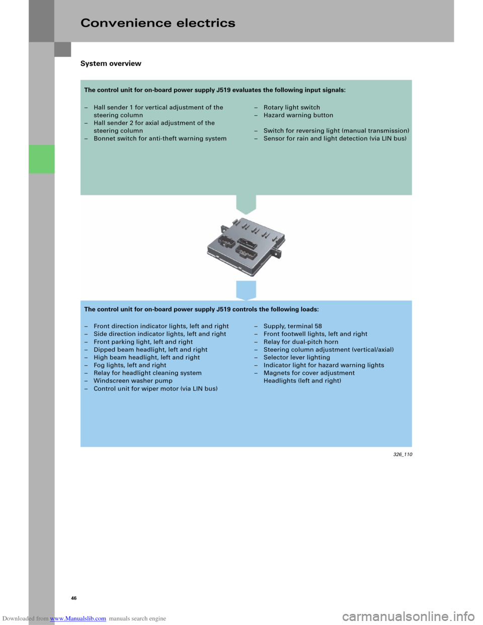
System overview
Convenience electrics
– Hall sender 1 for vertical adjustment of the
steering column
– Hall sender 2 for axial adjustment of the
steering column
– Bonnet switch for anti-theft warning system–Rotary light switch
–Hazard warning button
– Switch for reversing light (manual transmission)
– Sensor for rain and light detection (via LIN bus)
– Front direction indicator lights, left and right
– Side direction indicator lights, left and right
– Front parking light, left and right
– Dipped beam headlight, left and right
– High beam headlight, left and right
– Fog lights, left and right
– Relay for headlight cleaning system
– Windscreen washer pump
– Control unit for wiper motor (via LIN bus)– Supply, terminal 58
– Front footwell lights, left and right
– Relay for dual-pitch horn
– Steering column adjustment (vertical/axial)
– Selector lever lighting
– Indicator light for hazard warning lights
– Magnets for cover adjustment
Headlights (left and right)
326_110
The control unit for on-board power supply J519 evaluates the following input signals:
The control unit for on-board power supply J519 controls the following loads:
Page 45 of 92

Downloaded from www.Manualslib.com manuals search engine 47
Diagnosis
Basic settings
After the control unit for on-board power
supply J519 or the steering column or the switch for
steering column adjustment E167 is replaced, a
basic setting in axial and vertical position must be
implemented for the steering column.
Actuator test
An actuator test can be used to carry out the
following checks:
– Indicator light for hazard warning lights K6
– Lamp for parking light, left M1
– Lamp for parking light, right M3
– Lamp for dipped beam headlight, left M29
– Lamp for dipped beam headlight, right M31
– Lamp for high beam headlight, left M30
– Lamp for high beam headlight, right M32
– Lamp for left fog light L22
– Lamp for right fog light L23
– Lamp for daytime driving light, left L174
– Lamp for daytime driving light, right L175
– Direction indicator lights, left
– Direction indicator lights, right
– Footwell light, left W9
– Footwell light, right W10
– Wiper, top turning position
– Wiper, bottom turning position
– Windscreen washer pump V5
– Relay for dual-pitch horn
–Terminal 58
Coding
The control unit for on-board power supply J519 can
be coded for the functions
–Daytime driving light,
– Driving light assistant,
– Headlight type,
– Footwell lighting and
–Country versions
using the diagnosis tester.
Note
The actuator test can be performed either
sequentially (in sequence) or selectively
(individual selection).
Page 54 of 92
Downloaded from www.Manualslib.com manuals search engine 56
326_121
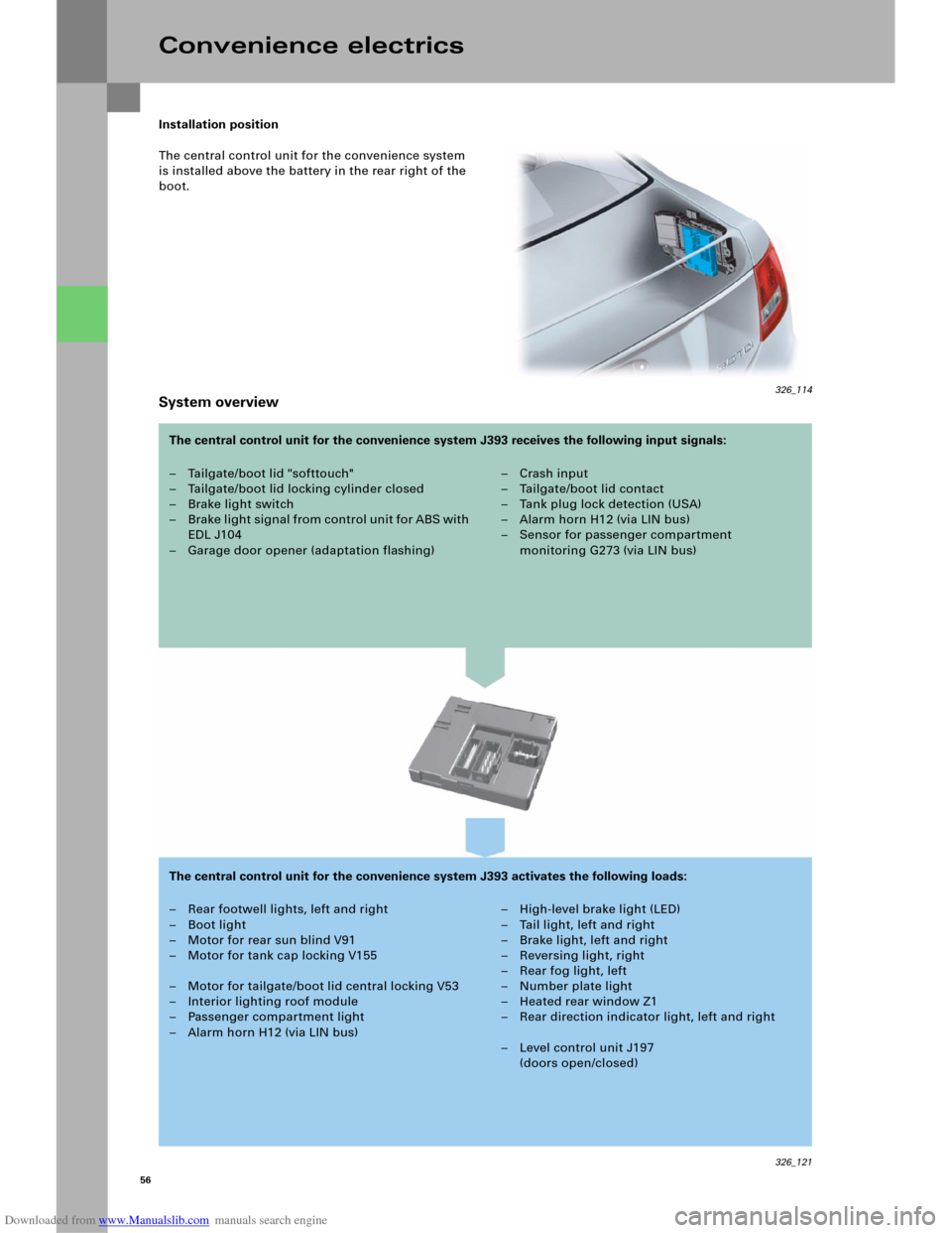
Installation position
The central control unit for the convenience system
is installed above the battery in the rear right of the
boot.
System overview
Convenience electrics
– Tailgate/boot lid "softtouch"
– Tailgate/boot lid locking cylinder closed
– Brake light switch
– B rake li ght signal from control u ni t fo r ABS with
EDL J104
– Garage door opener (adaptation flashing)– Crash input
– Tailgate/boot lid contact
–Tank plug lock detection (USA)
– Alarm horn H12 (via LIN bus)
– Sensor for passenger compartment
monitoring G273 (via LIN bus)
– Rear footwell lights, left and right
– Boot light
– Motor for rear sun blind V91
– Motor for tank cap locking V155
– Motor for tailgate/boot lid central locking V53
– Interior lighting roof module
– Passenger compartment light
– Alarm horn H12 (via LIN bus)– High-level brake light (LED)
– Tail light, left and right
–Brake light, left and right
– Reversing light, right
–Rear fog light, left
– Number plate light
– Heated rear window Z1
– Rear direction indicator light, left and right
– Level control unit J197
(doors open/closed) The central control unit for the convenience system J393 receives the following input signals:
The central control unit for the convenience system J393 activates the following loads:
326_114
Page 56 of 92
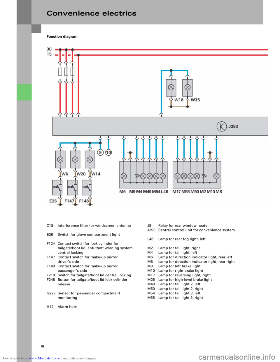
Downloaded from www.Manualslib.com manuals search engine 58
Function diagram
Convenience electrics
C18 Interference filter for windscreen antenna
E26 Switch for glove compartment light
F124 Contact switch for lock cylinder for
tailgate/boot lid, anti-theft warning system,
central locking
F147 Contact switch for make-up mirror
driver’s side
F148 Contact switch for make-up mirror
passenger’s side
F218 Switch for tailgate/boot lid central locking
F248 Button for tailgate/boot lid lock cylinder
release
G273 Sensor for passenger compartment
monitoring
H12 Alarm hornJ9 Relay for rear window heater
J393 Central control unit for convenience system
L46 Lamp for rear fog light, left
M2 Lamp for tail light, right
M4 Lamp for tail light, left
M6 Lamp for direction indicator light, rear left
M8 Lamp for direction indicator light, rear right
M9 Lamp for left brake light
M10 Lamp for right brake light
M17 Lamp for reversing light, right
M25 Lamp for high-level brake light
M49 Lamp for tail light 2, left
M50 Lamp for tail light 2, right
M54 Lamp for tail light 3, left
M55 Lamp for tail light 3, right