height AUDI A6 2005 C5 / 2.G Electrics System Training Manual
[x] Cancel search | Manufacturer: AUDI, Model Year: 2005, Model line: A6, Model: AUDI A6 2005 C5 / 2.GPages: 92, PDF Size: 4.42 MB
Page 64 of 92

Downloaded from www.Manualslib.com manuals search engine 66
Input and output signals
(driver’s seat)
Convenience electrics
Function
The control unit for seat adjustment powers the
positioning motors in the seat directly using its load
outputs. The position detection function of the
positioning motors is implemented using hall
sensors. The driver’s-side door control unit reads in
switch information from the operator unit for
memory, driver’s seat E97 as voltage-coded
information and sends this via CAN Convenience to
the control unit for seat adjustment with
steering-column adjustment memory J136.
The control unit for seat adjustment with
steering-column adjustment memory reads in
information from the switch for fore-and-aft and
height adjustment, driver’s seat E61, the switch for
backrest adjustment, driver’s seat E96 and the
switch for tilt adjustment, driver’s seat E222 directly.
The driver’s-side door control unit J386 reads in the
button information "Seat memory emergency-Off"
and supplies this discretely as well as in the form of
a CAN Convenience message to the control unit for
seat adjustment with steering-column adjustment
memory J136. Comfort functions, such as seat
symmetry positioning and comfort side view as well
as radio code allocation to a memory location, are
implemented using settings in the Multimedia
Interface (MMI).
Data bus diagnosis interface J533
Door control unit, driver's side J386Switch for fore-and-aft and height
adjustment, driver’s seat E61
Switch for backrest adjustment,
driver’s seat E96
Switch for tilt adjustment,
driver’s seat E222
Control unit for seat adjustment with
steering-column adjustment memory
J136
Operator unit for memory,
driver’s seat E97Discrete lead for
"Seat memory emergency-Off" signalPositioning motors
326_117
Page 77 of 92

Downloaded from www.Manualslib.com manuals search engine 79
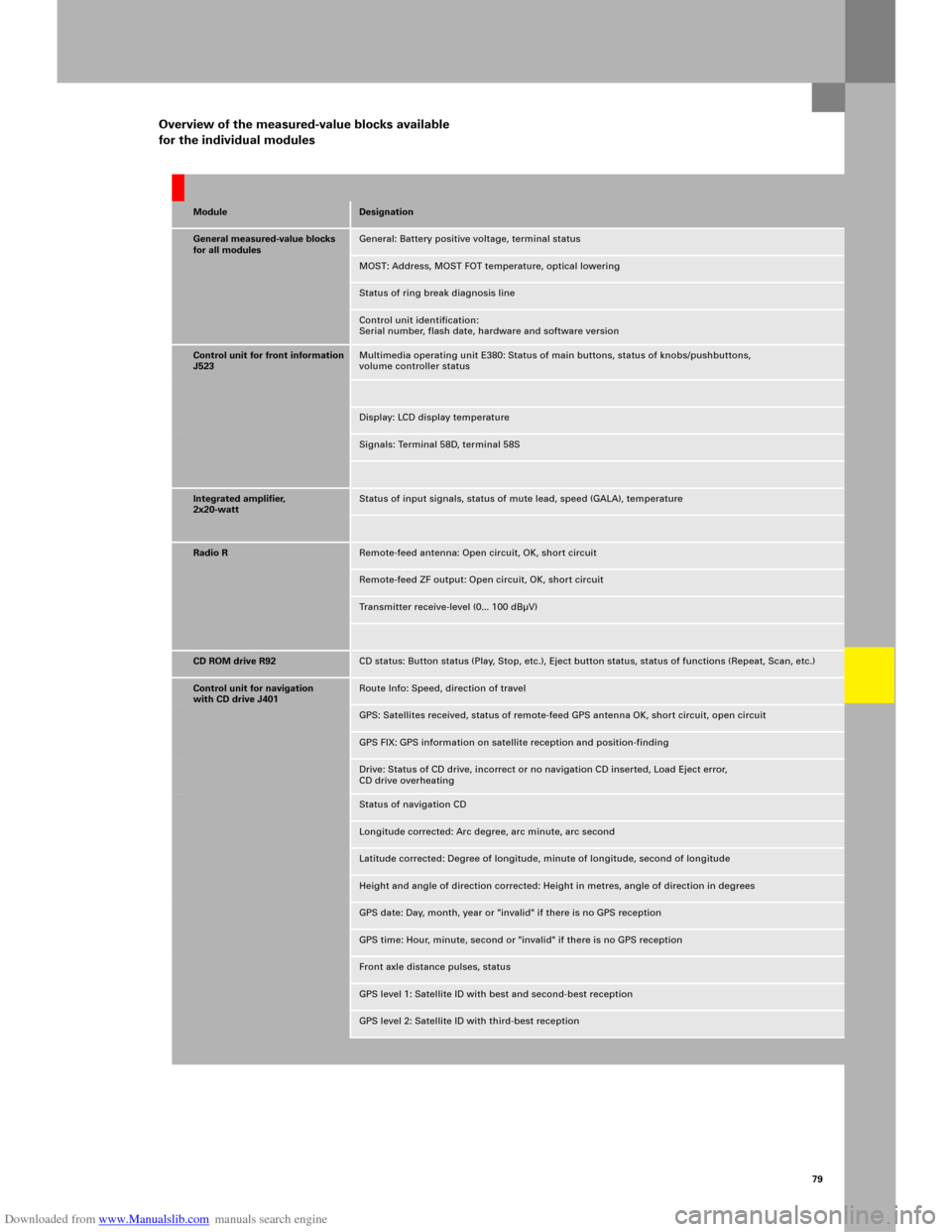
Overview of the measured-value blocks available
for the individual modules
ModuleDesignation
General measured-value blocks
for all modulesGeneral: Battery positive voltage, terminal status
MOST: Address, MOST FOT temperature, optical lowering
Status of ring break diagnosis line
Control unit identification:
Serial number, flash date, hardware and software version
Control unit for front information
J523Multimedia operating unit E380: Status of main buttons, status of knobs/pushbuttons,
volume controller status
Display: LCD display temperature
Signals: Terminal 58D, terminal 58S
Integrated amplifier,
2x20-wattStatus of input signals, status of mute lead, speed (GALA), temperature
Radio RRemote-feed antenna: Open circuit, OK, short circuit
Remote-feed ZF output: Open circuit, OK, short circuit
Transmitter receive-level (0... 100 dBµV)
CD ROM drive R92CD status: Button status (Play, Stop, etc.), Eject button status, status of functions (Repeat, Scan, etc.)
Control unit for navigation
with CD drive J401Route Info: Speed, direction of travel
GPS: Satellites received, status of remote-feed GPS antenna OK, short circuit, open circuit
GPS FIX: GPS information on satellite reception and position-finding
Drive: Status of CD drive, incorrect or no navigation CD inserted, Load Eject error,
CD drive overheating
Status of navigation CD
Longitude corrected: Arc degree, arc minute, arc second
Latitude corrected: Degree of longitude, minute of longitude, second of longitude
Height and angle of direction corrected: Height in metres, angle of direction in degrees
GPS date: Day, month, year or "invalid" if there is no GPS reception
GPS time: Hour, minute, second or "invalid" if there is no GPS reception
Front axle distance pulses, status
GPS level 1: Satellite ID with best and second-best reception
GPS level 2: Satellite ID with third-best reception