check engine AUDI A6 2015 Owner's Guide
[x] Cancel search | Manufacturer: AUDI, Model Year: 2015, Model line: A6, Model: AUDI A6 2015Pages: 314, PDF Size: 77.57 MB
Page 233 of 314
M N
0 I.J "". rl I.O
"' rl
"' rl
Brake fluid
Checking brake fluid level
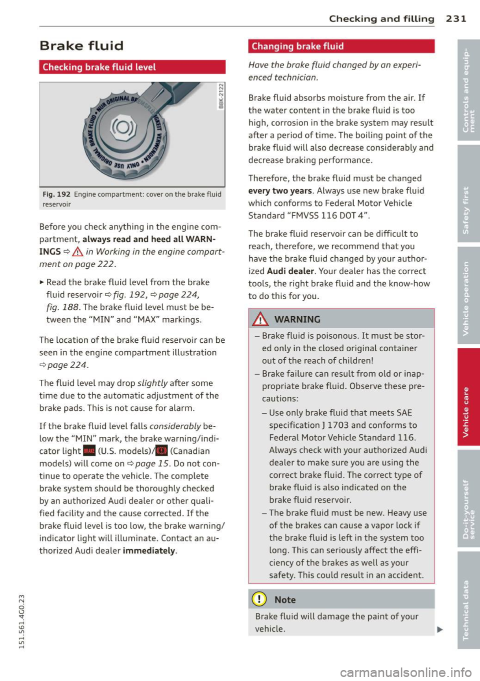
Fig. 192 Engine co mpa rtment: cove r on the b rake f luid
reservo ir
Before you check anything in the engine com
partment,
al ways r ead and h eed all WARN·
ING S ¢ &. in Working in the engine compart
ment on page 222.
.. Read the brake fluid level from the brake
fl uid reservoir¢
fig. 192, ¢ page 224,
fig. 188 .
The brake f luid level must be be
tween the "MIN" and "MAX" markings .
The location of the brake flu id reservo ir can be
seen in the engine compa rtment illust rat ion
¢ page 224.
The fluid level may drop slightly after some
time due to the automatic adjustment of the brake pads. This is not cause for alarm.
If the brake fluid level falls
considerably be
low the "MIN" mark, the brake wa rning/indi
cator ligh t. (U .S. models) . (Canad ian
models) will come on ¢
page 15. Do not con
tinue to operate the vehicle. The comp lete
brake system shou ld be thoroughly checked
by an authorized A udi dealer or other quali
fied facility and the cause corrected.
If the
br ake fluid level is too low, the brake warn ing/
indicator light w ill illuminate. Contact an au·
thor ized Audi dealer
imm ediately .
Checkin g and fillin g 231
Changing brake fluid
Have the brake fluid changed by an experi·
enced technician .
Brake fluid absorbs mois ture from the air. If
the wa ter content in the brake fluid is too
high , corrosion in the brake system may result
after a period of time . The boiling point of the
brake flu id will also dec rease considerably and
decrease braking pe rformance.
Therefore, the brake fluid must be changed
ev ery two years. Always use new brake flu id
which conforms to Federal Motor Vehicle
Standard "F MVSS 116 DOT 4".
The brake fluid reservo ir can be d iff icult to
reach, the refore, we recommend that you
have the brake fluid changed by your author
i zed
Audi d ealer . Your dealer has t he correct
tools, the right brake fl uid and t he know-how
to do this for you .
A WARNING
-.
-Brake fluid is poisonous . It must be stor
ed only in the closed original container
out of the reach of children!
- Brake failure can resu lt from o ld or inap
propriate brake f luid. Observe these pre
cautions:
- Use only brake fluid that meets SAE
spe cificat ion
J 1 7 03 and conforms to
Federa l Moto r Ve hicl e Standard 116.
Always check with yo ur authorized Audi
dealer to make sure yo u are using the
correct bra ke fluid. The correct type of
brake f luid is also indicated on the
brake f luid reservoir.
- The brake fluid must be new. Heavy use
of the brakes can cause a vapor lock if
the brake fluid is left in the system too
l ong . This can seriously affect the effi
c iency of the brakes as well as your
safety. Th is cou ld resu lt in an accident.
(D Note
Brake fluid will damage the paint of your
vehicle .
Page 236 of 314

234 Checking and filling
(D Note
-Do not disconnect the vehicle battery
when the ignition is on or when the en
gine is running, otherwise, you will dam
age electronic components in the electri
cal system.
- If your vehicle is going to stand for a
long period of time without being driven,
protect the battery from "freezing", oth
erwise it w ill be damaged and w ill then
have to be replaced.
Battery charging
Starting the engine requires a well charged
battery.
Fi g. 19 3 Engine compartment : connectors for a charg ·
er and jump sta rt cables
Alway s re ad and h eed all WARNINGS below
c:> & and c:> & in Working on the battery on
page 233 .
• Switch off the ignitio n and all electrical con
sumers.
• Make sure the area is well vent ilated when
yo u charge the battery .
• Open the engine hood
i=!.> page 222.
• Open the red cover o n the pos itive pole
e!.>fig. 193.
• Connect the charger connectors according to
the instructions to the
jump start bolt s.
(Bolts under the red cover= "positive", Bolts
with hex head= "negative").
• Only now plug the mains lead for the charg
ing equipment into the wall outlet and turn
it on
c::> .&,. .
• Mak e sure th e charging rate is not over
30 amp s/14 .8 Volt .
• When the battery is fully charged: Turn the
charging equipment off and remove the
mains lead from the wall out let.
• Now remove the clamps for the charging
equ ipment.
• Close the red cover on the positive pole.
• Close the hood
c::> page 223 .
A discharged battery can freeze at tempera
tures of only 32 F
0 (0 °C). Allow a frozen bat
tery to thaw completely before attempting to charge it
c::> ,&. . However, we recommend not
u sing a thawed batte ry aga in because the bat
tery casing can be c racked due to ice fo rm a
t io n an d can leak battery a cid.
Battery charging (Maximum charging rate
of
30 amps/14.8 Volt )
When charg ing at low vo lt a ges (e.g. wi th a
trickle charger ), the battery cables do not
have to be disconnected firs t. T he battery
caps should
not be opened when charg ing a
battery .
It is no t necessa ry to remove the battery from
the luggage compartment, and it is a lso not
necessary to d isconnect the cab les .
Fast charging the battery (charging rate
above 14.8 Volts )
For technica l reasons do not use a battery
c h arger that uses voltage greater than
14.8
Volts to charge yo ur vehicle's battery.
Ln._ WARNING
--
Charging a battery can be dangerous.
- Always follow t he operati ng instructions
provided by the battery charger manu
facturer when charg ing your battery.
- Never cha rge a frozen battery . It may ex
p lode because of gas trapped in the ice.
Allow a frozen batte ry to thaw out f irst.
- Do not reuse batteries wh ich were fro
zen. The battery housing may have
cracked and weakened when the battery
froze.
Page 237 of 314
M N
0 <.J 'SI: ,...., \!) ..,.,
,...., ..,., ,....,
-Charge the battery in a well ventilated
area. Keep away from open flame or elec
trical spark. Do not smoke. Hydrogen gas generated by the battery is explosive.
- To reduce the danger of explosion, never
connect or disconnect charger cables
while the charger is operating.
- Fast charging a battery is dangerous and
should only be attempted by a compe
tent technician with the proper equip
ment.
- Battery acid that may spill during charg
ing should be washed
off with a solution
of warm water and baking soda to neu
tralize the acid.
(D Note
Never use a fast charger as a booster to
start the engine. This will seriously dam
age sensitive electronic components, such
as control units, relays, radio, etc., as well
as the battery charger.
Battery replacement
The new battery must have the same specifi
cations and dimensions as the original equip
ment battery.
Intelligent energy management in your vehi
cle is responsible for distributing the electri
cal energy throughout your vehicle
qpage 198. The intelligent energy manage
ment system will keep the engine battery
charged better than vehicles without this sys
tem. To make sure the additional electrical en
ergy is available once again after you have
changed the battery, we recommend that you install batteries of the same type and manu
facture only (the same as those installed at
the time your vehicle was delivered). Specifi
cations are listed on the battery housing. Your
authorized dealer must code the battery in
the energy management system to enable you
to use the energy management functions cor
rectly after replacing the battery.
Checking and filling 235
The new battery must have the same capacity,
voltage (12-volts), amperage, construction and plug sealing.
When installing the battery, make sure the ig nition and all electrical consumers are switch
ed off.
(D Note
Make sure the ventilation hose on the side
of the battery is connected, otherwise
fumes or battery acid can leak out.
- Vehicles with the Start-Stop-System* are
equipped with a special cycle-proof AGM
battery. Installing a different type of
battery can cause problems in the vehi
cle electrical system. When replacing the
vehicle battery, always install one with
the same specifications as the original
battery.
@ For the sake of the environment
Because of the problem of proper disposal
of a battery, we recommend your author
ized Audi dealer change the battery for
you. Batteries contain sulfuric acid and
lead and must always be disposed of prop
erly in compliance with all environmental
regulations. Disposing of vehicle batteries
improperly is very dangerous to the envi
ronment.
Windshield/headlight*
washer container
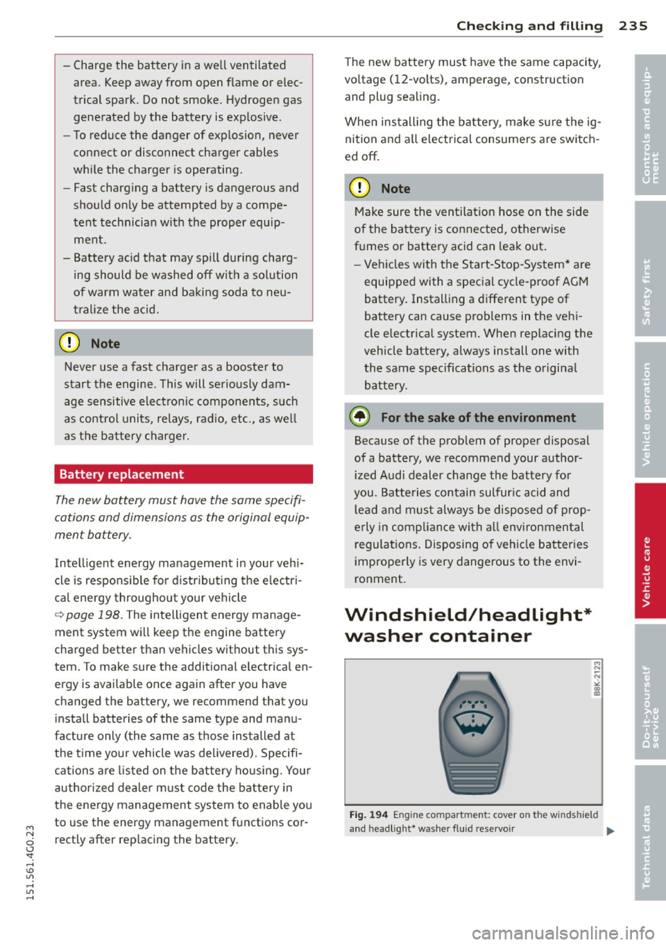
Fig. 194 E ng in e compart ment : cov er on th e w in ds hield
and headl ig ht* washer f luid reservoir
II-
•
•
Page 238 of 314

236 Checking and filling
The washer fluid container is marked with the
symbol$ on its cap
¢ fig . 194, ¢page 224,
fig. 188 .
.,. Before you check anything in the engine
compartment,
always read and heed all
WARNINGS ¢ A in Working in the engine
compartment on page
222 .
.,. Lift the filler cap tongue to add washer flu
id . You can fill the container to the top .
.,. Press the cap back onto the filler neck after
filling the container .
You can find the reservoir
capacity in the table
in¢
page 290.
C lean water sho uld be used when filling up. If
possible, use soft water to prevent sca ling on
washer jets. Always add a glass cleaner solu
tion (with frost protection in the winter).
Do not mix engine coolant antifreeze or
any other additives to f ill up the wind
shield washer reservoir.
Page 275 of 314
M N
0 <.J 'SI: ,...., \!) ..,.,
,...., ..,., ,....,
A WARNING 1=
You or your passengers could be injured
while changing a wheel if you do not fol
low these safety precautions:
- If you have a flat tire, move a safe dis
tance off the road. Turn off the engine,
turn the emergency flashers on and use
other warning devices to alert other mo
torists.
- Make sure that passengers wait in a safe
place away from the vehicle and well
away from the road and traffic.
- To help prevent the vehicle from moving
suddenly and possibly slipping off the
jack, always fully set the parking brake
and block the wheel diagonally opposite
the wheel being changed. When one
front wheel is lifted off the ground, plac
ing the Automatic Transmission in P
(Park) will
not prevent the vehicle from
moving.
- Before you change a wheel, be sure the
ground is level and firm. If necessary,
use a sturdy board under the jack.
- Always store the vehicle tool kit, the jack
and the replaced tire in the luggage com
partment
¢ page 132.
{!) Tips
Before changing the wheel, you must acti
vate the jacking mode, so that the auto matic controls for the Adaptive Air Sus
pension* do not make it more difficult to
lift the vehicle with the jack¢
page 2 75.
Changing a wheel
When you change a wheel, follow the se
quence described below step-by-step and in
exactly that order .
1. Activate the vehicle jack mode*
c::;. page 275.
-
2. Remove the decorative wheel cover* . For
more details see also
¢page 274, Deco
rative wheel covers
or ¢ page 2 7 4,
Wheels with wheel bolt caps.
3. Loosen the wheel bolts¢ page 274.
What do I do now? 273
4.
5.
6.
7.
8.
9.
Locate the proper mounting point for the
jack and align the jack below that point
¢page 275.
Raise the car with the jack ¢page 275.
Remove the wheel with the flat tire and
then install
the spare <=> page 2 76.
Tighten all wheel bolts lightly.
Lower the vehicle with the jack .
Use the wheel bolt wrench and
firmly
tighten all wheel bolts¢ page 274 .
10. Replace the decorative wheel cover*.
11. Deactivate the vehicle jack mode* in the
MMI:
ICARI function button > (Car)* sys
tems
control button > Servicing & checks
> Air susp.: jack mode > Off .
The vehicle jack mode* switches off automati
cally at speeds above 6 mph (10 km/h).
A WARNING
Always read and follow all WARNINGS and information<=>
A in Raising the vehicle on
page 275
and <=> page 277.
After changing a wheel
A wheel change is not complete without the
doing the following.
.,. Always store the vehicle tool kit, the jack*
and the replaced tire in the luggage com
partment
c::;. page 132.
.,. Check the tire pressure on the spare wheel
immediately after mounting it.
.,. As soon as possible, have the
tightening
torques
on all wheel bolts checked with a
torque wrench. The correct tightening tor
que is
90 ft lb (120 Nm) .
.,. Have the flat tire
replaced as soon as possi
ble.
(D Tips
- If you notice that the wheel bolts are
corroded and difficult to turn while
changing a tire, they should be replaced
before you check the tightening torque.
- Drive at reduced speed until you have the
tightening torques checked.
ll>
•
•
Page 281 of 314

M N
0 I.J "". rl I.O
Fuses and bulbs
Fuses
Replacing fuses
Fuses that have blown will have metal strips
that have burned through.
Fig . 2 14 Driver side of the cockp it: fuse panel cove r
The fuses are located at the front left and
r igh t of the cockpit and behi nd the trim on
the right side of the luggage compartment .
.. Switch the ign ition and the affected electr i
ca l equ ipment off .
.. Check the following table to see which fuse
belongs to the consume r .
.. Remove the cover
r:!;> fig. 214 or r:!;> page 218,
Opening the side trim .
.. To remove the purple plastic cl ip if necessa
ry
ll, hold onto it at the small s ide and pull
it out of the fuse panel
r:!;> page 279,
fig. 215 .
.. Remove the clamp from the rea r side of the
fuse cover ¢
fig. 214 .
.. Remove the fuse using the cl amp and re
pla ce the blown fuse w ith an identical new
one.
& WARNING , -
Do not repair f uses and never replace a
blown fuse w ith one that has a higher amp
rating. This can cause damage to the e lec
trical system and a fire.
"' rl
~ 11 You can dis pose of the plastic clip after remov ing it.
Fu se s and bulb s 2 79
(D Note
If a new fuse burns out again after short ly
have you have insta lled it, have the electri
ca l system c hecked by yo ur authorized
A udi dealer .
{!) Tips
-The following table does not list fuse lo
cat ions that are not used .
- Some of the equipment items listed are
opt ional or only available on certa in
mode l configurations.
Driver side cockpit fuse assignment
Fi g. 215 Dr iver side cockpit : fuse pa nel w ith plastic
bracket
Fuse panel @ (blac k)
No . Equipment Amps
Switch panel, electromechanica l
1 parking brake, seat heating, 5
starting assist, control module
2 Au toma tic d imm ing in terior
5 rearview mir ro r, horn
3 Exhaust system (diesel engine) 10
Page 287 of 314

M N
0 I.J "". rl I.O
"' rl
"' rl
-When connecting jumper cables, make
sure that they cannot get caught in any
moving parts in the eng ine compart
ment .
- Before you check anything in the engine
compartment, always read and heed all
WARNINGS
¢ page 222.
(D Note
Improper hook-up of jumper cables can r u
in the generator.
- Always connect POSITIVE( +) to POSI
TIVE(+), and NEGATIVE(-) to NEGATIVE
( - ) gro und post of the battery manager
control unit .
- Check that all screw plugs on the battery
cells a re screwed in firmly . If not, tighten
pl ugs p rior to connecting clamp on nega
tive battery term inal.
- Please note that the procedure f or con
nect ing a jump er cable as desc ribed
above appl ies spec ifically to the case of
you r vehi cle be ing jump started. When
you are giv ing a jump star t to an othe r ve
hi cle, do
not connec t the negat ive (-) ca
ble to the negat ive (-) terminal on the
discharged battery@¢fig.
219. In
stead, securely connect the negative( -)
cable to e ithe r a solid metal component
that is firmly bolted to the engine block
or to the e ng ine block itse lf. If the bat
te ry tha t is being charged does not vent
to the outside, escaping batte ry gas
could igni te and exp lode!
Emergency towing
with commercial tow truck
General hints
Your Audi requires special handling for tow
tng.
The follow ing information is to be used by
commercia l tow tr uck operators who know
h ow to ope rate thei r equipme nt safe ly.
Emergenc y situ ation s 285
-Ne ver tow your Audi. Towing will cause
damage to the engine and tran smission.
- Never wrap the safety chain s or w inch ca
ble s around the brake lines.
- To prevent unnece ssary damage , your Audi
must be transported with a flat bed tru ck.
- To load the vehicle on to the fl at bed , use
the towing loop found in the vehicle tools
a nd attach to the front or rear anchora ge
¢ page 285 and ¢ page 286 .
_& WARNING
A vehicle being towed is not safe for pas
sengers. Never allow anyo ne to ride in a
vehicle be ing towed, for any reason.
Front towing loop
Only install the front towing loop when it is
needed.
Fig. 22 0 Front bu mpe r: cove r
Fig. 22 1 Front bu mpe r: in stall ing t he tow ing loop
-
The towing loop fits into the threaded hole lo
cated on the right s ide of the front bumpe r
and cove red by a sma ll cover when not in use.
.. Remove the tow ing loop from the vehicle
too l kit .
Page 290 of 314
288 Emergency situations
heavy components such as the engine
b lock or transmiss io n are removed.
- W he n removing heavy components like
these, ancho r vehicle to ho ist o r add cor
responding weig hts to ma inta in the cen
ter of g ravity . Othe rwise, the vehicle
might tilt or s lip off t he hoist, causing
ser ious p erson al injury.
(D Note
-Be awa re of the follow ing points befo re
li fting the vehicle:
- The vehicle should never be lifted or
jacked up from underneath the engine oil pan, the transmission housing, the
front or rear axle or the body side
membe rs. This could lead to ser ious
damage.
- To avoid damage to the underbody or
chassis frame , a rubber pad must be
i nserted between the floor jack and
the l ift points.
- Before driving over a workshop hoist,
check that the veh icle weight does not
exceed the permissible lifting capacity
of the hoist .
- Before driving over a workshop hoist,
ensure that there is sufficient clear
ance between the hoist and low parts
of the vehicle.
Page 291 of 314
M N
0 I.J ""'. rl I.O
"' rl
"' rl
Technical data
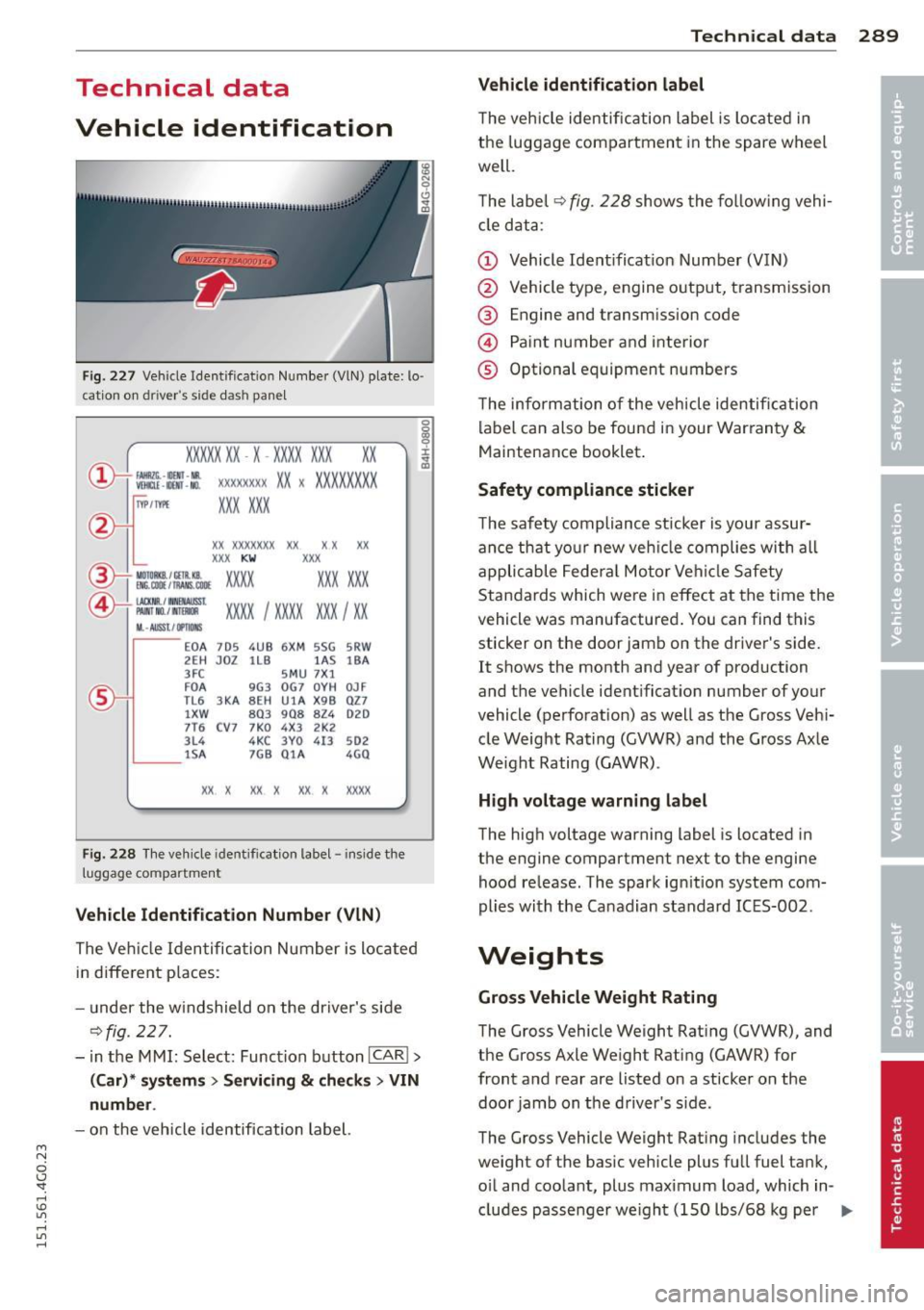
Vehicle identification
F ig. 227 Veh ide Identificat ion Number (VlN) plate: lo ·
c ation on d river 's s ide das h pane l
XXXXX XX · X -XXXX XXX
~ fAllftlli. -llllll · NR. ~ W!ru -IIOO -NO.
xx
XXXX XXXX XX X XXXXXXXX
XXX XXX
IYP /TYPE
XX XXXXXXX XX X X XX
XXX KW XXX
®i ~W.::·f :l~~ XXXX XXX XXX
©+ ::rw= xxxx I xxxx XXX I xx
M. · AUSSt I IJ'IIDIIS
~--
EOA 7D 5 4UB 6XM SSG SRW
2E H JOZ 1LB lA S 18A
3FC SMU 7X l
FD A 9G3 OG7 OYH OJF
TL6 3 KA 8EH UlA X98 027
lXW 803 908 824 D2D
7T6 CV7 7KO 4X3 2K2
3L4 4KC 3YO 413 502
1S A 7GB 01A 4GO
XX. X XX X XX X XXXX
Fig. 228
The vehicle identification label - inside the
luggage co mpartment
Vehicle Identification Number (VlN)
The Veh icle Identification Number is located
in different p laces :
- under the w indshield on the driver's side
¢fig. 227.
- in the MMI: Select: Function button ICAR ! >
(Car)* systems> Servicing & checks > VIN
number.
- on the vehicle identification label.
Techni cal data 289
Vehicle identification label
The vehicle identification label is located in
the luggage compartment in the spare wheel
well.
T he label¢
fig. 228 shows the following vehi
cle data :
(D Vehicle Identificat ion Number (VIN)
@ Vehicle type, engine output, transmission
® Engine and transmission code
© Paint number and interior
® Optional equipment numbers
The information of the veh icle identification
label can also be found in your Warranty
&
Maintenance booklet .
Safety compliance sticker
The safety compliance sticker is your assur
ance that your new veh icle complies with all
applicable Federal Motor Vehicle Safety
Standards which were in effect at the time the
vehicle was manufactured . You can find this
sticker on the door jamb on the driver's side. It shows the month and year of production
and the vehicle ident ification number of your
vehicle (perforation) as well as the Gross Vehi
cle Weight Rating (GVWR) and the Gross Axle
Weight Rating (GAWR) .
High voltage warning label
The high voltage warning label is located in
the engine compartment next to the engine hood release. The spark ignition system com
plies with the Canadian standard ICES-002 .
Weights
Gross Vehicle Weight Rating
The Gross Vehicle Weight Rating (GVWR), and
the Gross Axle Weight Rating (GAWR) for
front and rear are listed on a sticker on the
door jamb on the driver's s ide.
The Gross Vehicle Weight Rating includes the
weight of the basic vehicle plus full fuel tank,
oil and coolant, plus maximum load, which in
cludes passenger we ight (150 lbs/68 kg per
II>--
Page 295 of 314

M N
0 <.J 'SI: ,...., \!) 1.1'1 ,...., 1.1'1 ,....,
complexity of today's automobi les, have
steadi ly reduced the scope of maintenance
and repairs which can be carried out by vehicle
owners.
Also, safe ty and e nvir onm en tal con
cerns place very strict limits on the nature of
repairs and adjustments to engine and trans
miss io n pa rts which an owner can perform .
Maintenance, adjustments and repairs usua lly
require special tools, testing devices and oth
er equipment avai lab le to specially trained
workshop personnel in order to assure prope r
performance, reliab ility and safety of the vehi
cle and its many systems .
Improper ma intenance, adjustments and re
pa irs can impair the operation and reliability
of your vehicle and even void your vehicle war ranty. The refo re, p roof of servici ng in accord
ance w ith the maintenance sched ule may be a
condition for upholding a poss ible war ranty
claim made within the warranty period.
Above all, operational safety can be adversely
affected, crea ting unnecessary risks for you
and your passengers.
If in doubt about any servicing, have it done
by your authori zed Audi dealer or any other
properly equipped and q ualified workshop .
We strong ly urge you to give you r a uthorized
Audi dealer the opportunity to perform all
schedu led maintenance and necessary repairs .
Your dea ler has the facilities, or iginal parts
and trained spec ialists to keep your vehicle
running properly .
Performing limit ed m aintenance you rself
The following pages describe a limited num
ber of procedu res which can be performed on
your vehicle with ordinary too ls, should the
need arise and trained personnel be unavaila
b le. Before performing any of these proce
dures, always tho roughly read a ll of the app li
cable text and carefully follow the instruc
tions given . Always rigorously obse rve the
WARNINGS provided .
Before you check anything in th e engine
compartment, a lway s re ad and heed all
Con sumer In formation 293
WARNINGS ¢ & and ¢ & in Working in the
engine comportment on page 222 .
A WARNING
-Ser ious personal injury may occur as a re
sult of improperly performed mainte nance, adjustments or repa irs.
-Always be extremely care ful when work
ing on the vehicle. Always follow com
mon ly accepted safety practices and gen
era l common sense . Never r isk personal
lnJU ry .
- Do not attempt any of the ma intenance ,
checks or repairs descr ibed on the fol
lowing pages if you are not fully fam ilia r
wit h these or othe r pro cedures with re
spect to t he veh icle, or are uncerta in how
to p roceed .
- Do not do any work without the proper
too ls and equipment. Have the necessary
work done by your authorized A udi deal
er or another proper ly equipped and
qualified workshop .
- The engine compar tment o f any motor
veh icle is a potentially hazardous area.
Never reach into the area around or
touch the radiator fan. It is temperature
contro lled and can switch on suddenly -
even when the engine is
off . The radiator
fan switches on automat ica lly when the
coo lant reaches a certai n tempe rature
a nd will cont inue to run until the coo lan t
temper ature drops.
- Always sw itch
off the ignition before any
one gets under the vehicle.
- Always support your veh icle with safety
stands if it is necessary to work under
neath the vehicle. The j ack s upplied with
the vehicle is not adequa te for this pur
pose and cou ld collapse causing serio us
personal i njury .
- I f you must work unde rne ath the vehicle
with the wheels on t he g ro und, a lways
make sure the vehicle is on leve l ground,
that the wheels are a lways securely
blocked and that the engine cannot be
started.
•
•