inter AUDI A6 2016 Owners Manual
[x] Cancel search | Manufacturer: AUDI, Model Year: 2016, Model line: A6, Model: AUDI A6 2016Pages: 294, PDF Size: 73.88 MB
Page 250 of 294
Wheels
- These tires may wear more q uickly than othe rs.
- Please also remembe r th at, w hile these tires
deliver responsive handling, they may r ide less
comfortably and make more noise than ot her
cho ices.
Reduced performance in wint er/ cold season
condit ion s
All tires are designed for certain purposes. The low aspect ratio, ultra high pe rformance tires
or iginally insta lled on yo ur vehicle are intended
for maximum d ry and wet road performance and
handling. They are not suitable for cold, snowy or
icy weathe r cond itions .
If you drive under those
circumstances, you should equ ip your ve hicle
with all-season or winter tires, wh ich offe r bette r
traction under those condit ions. We sugges t you
use the recommended snow or all-season tires
specified for yo ur vehicle, or their eq uivalen t.
Refer to¢
page 246 for more deta iled info rma·
tion reg arding w in ter ti res.
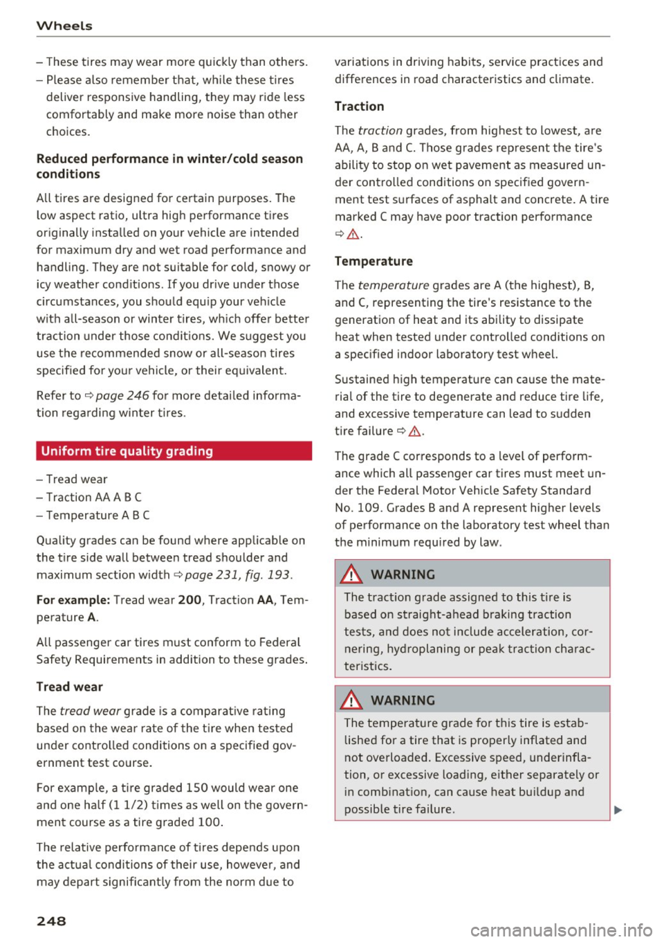
Uniform tire quality grading
- Tread we ar
- Tra ction AA A B C
- Temperature ABC
Qua lity grades can be found where app licab le on
the t ire side wall betwee n tread s hou lder and
maximum sect io n w idth ¢
page 231, fig . 193.
For e xample: Tread wear 200 , T raction AA, Tern·
pe rature A.
All passenger car tires must conform to Federa l
Safety Requirements in addition to these grades .
Tread wear
T he
tread wear grade is a compara tive ra ting
b a se d on the wea r rate of the t ire when tes ted
under contro lled conditions on a specified gov ·
ernment test co urse.
F or examp le, a tir e graded 150 would wear one
a nd one ha lf ( 11/2) times as well on t he gove rn·
men t course as a tire graded 100 .
T he rela tive perfo rmance of t ires depends upon
the a ct u a l c ondi tions of their use, howeve r, and
may depart s ignific ant ly from the norm d ue to
248
variations in driving habits, service p ract ices an d
differences in road characteristics and climate.
Traction
The
traction grades , from hig hest to lowest , a re
AA , A, B and
C. Those grades rep resent the tire's
a bility to stop o n wet p avement as measure d un
der controlled conditions on specified govern ·
ment test s urfaces of asphalt an d concrete. A tire
marked C may have poor traction perfo rmance
¢ ,& .
Temperature
The
temp eratur e grades are A ( the highest), B,
and C, representing the tire 's resistance to the
generatio n of heat and its ability to dissipate
heat when tested under contro lled conditions on
a specified indoor laboratory test wheel.
Sustained high temperature can cause the mate·
rial of the tire to degenerate and reduce tire life,
and excessive temperature can lead to s udden
tire failure¢ ,&.
The grade C cor responds to a level of perform ·
ance which all passenger car tires must meet un·
der the Federal Motor Vehicle Safety Standard
No . 109 . Grades Band A represent hig her levels
of performance on the laboratory test wheel than
t h e m inim um requ ired by law .
A WARNING
-
The tract io n grade assigned to this t ire is
based on st raig ht-a head braking tr action
tes ts, and do es not in clude acceler ation, cor·
n erin g, hy droplaning or pe ak traction ch arac
teristics.
A WARNING
T he tem pera ture grade fo r thi s tire is esta b·
lishe d for a tire that is properly inflated and
not ove rloaded . Excessive speed, underinfla ·
tion, o r excessive load ing, either separately or
in comb inat ion, can cause heat bu ildup and
-
possible tire failure . ..,
Page 252 of 294
Wheels
the recommended tire pressure for your vehicle
¢ page 241, fig. 196.
Tire tread circumference and vibration character
istics can change and cause a tire pressure warn
ing if:
- the tire pressure in one or more tires is too low.
- the tire has structural damage .
- the tire was replaced or the tire pressure was
changed and it was not stored¢
page 250.
-the spare tire* is installed.
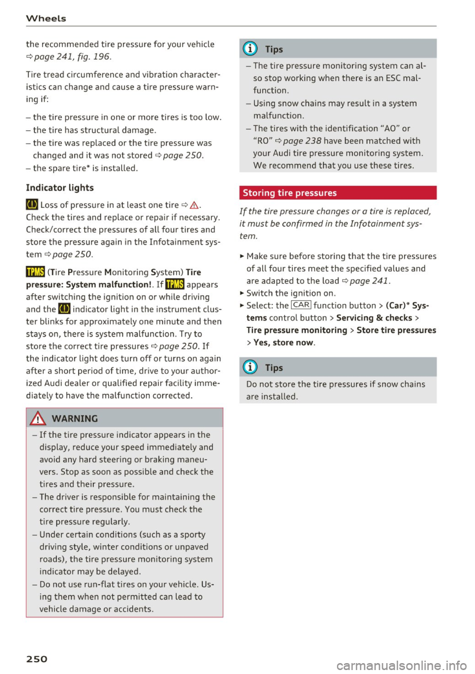
Indicator lights
IE Loss of pressure in at least one tire¢&. .
Check the tires and replace or repair if necessary.
Check/correct the pressures of all four tires and
store the pressure again in the Infotainment sys
tem ¢
page 250 .
mm (Tire Pressure Monitoring System) Tire
pressure: System malfunction!.
Ifmm appears
after switching the ignition on or while driving
and the
IE indicator light in the instrument clus
ter blinks for approximately one minute and then
stays on , there is system malfunction . Try to
store the correct tire pressures¢
page 250. If
the indicator light does turn off or turns on again
after a short period of time, drive to your author
ized Audi dealer or qualified repair facility imme
diate ly to have the malfunction corrected.
A WARNING
- If the ti re pressure indicator appears in the
display, reduce your speed immediately and
avoid any hard steering or braking maneu
vers. Stop as soon as possible and check the
t ir es and their pressure .
- The driver is responsible for maintaining the
correct tire pressure. You must check the
t ir e pressure regularly.
- Under certain conditions (such as a sporty
dr iv ing style, winter cond itions or unpaved
roads), the tire pressure mon itoring system
indicator may be delayed.
- Do not use run-flat tires on your vehicle. Us
ing them when not permitted can lead to
vehicle damage or accidents.
250
(D Tips
-The tire pressure monitoring system can al
so stop working when there is an ESC mal
function.
- Using snow chains may result in a system
malfunction.
- The tires with the identification "AO" or
"RO" ¢
page 2 38 have been matched with
your Audi tire pressure monitoring system.
We recommend that you use these tires.
Storing tire pressures
If the tire pressure changes or a tire is replaced,
it mus t be confirmed in the Infotainmen t sys
tem.
... Make sure before storing that the tire pressures
of all four tires meet the specified values and
are adapted to the load ¢
page 241.
... Switch the ignition on .
... Select: the
I CARI function button > (Car)* Sys
tems
contro l button > Servicing & checks >
Tire pressure monitoring > Store tire pressures
> Yes, store now.
(D Tips
Do not sto re the tire pressures if snow chains
a re installed.
Page 255 of 294
-The spare tire is intended on ly for tempora
ry and short-term use. It shou ld be replaced
as soon as possible with the normal wheel
and t ire.
- After mounting the compact spare tire, the
tire pressure must be checked as soon as
poss ible. The t ire pressure of the compact
spare tire m ust be 4.2 bar; otherwise, you
risk having an accident.
- Do not drive faster than SO mph (80 km/h).
You risk hav ing an accident .
-Avoid full-throttle accelerat ion, heavy brak
ing, and fast cornering . You risk having an
acc ident.
- Never drive us ing more than one spare
wheel and tire . You risk having an acc ident.
- Normal summer or winter tires must not be
mounted on the compact spare wheel rim .
- For technical reasons, the use of tire chains
on the spare tire is not perm itted. If it is
necessary to drive with t ire chains, the spare
wheel m ust be mounted on the front axle i n
the even t of a flat in a rea r tire. The new ly
avail able front wheel m ust then be insta lled
in place of the rear wheel with the flat tire .
Installing the tire chain before mounting
the wheel and tire is recommended .
- Loose items in the passenger compartment
can cause ser ious personal injury during
hard braking or in an acc ident. Never store
the inflatable spare t ire or jack and too ls in
the passenger compartment.
Replacing wheels
Before changing a wheel
Observe the following precautions for your own
and your passenger's safety when changing a
wheel.
• After you experience a tire failure , pull the car
well away from moving t raff ic and try to reach
level ground before you stop¢ A-
• All passengers sho uld leave the car and move
to a safe location (fo r instance, be hind the
guardrail) ¢
A.
• Engage the parking b rake to prevent yo ur vehi
cle from roll ing unintentionally ¢
A-
Em ergenc y ass is tanc e
• Move selecto r lever t o po sit ion P ¢ A .
• If you are towing a trai ler, unhitch the trailer
from yo ur vehicle .
• Take the
jack and the spare tire out of the lug
gage compartment
¢page 251, ¢page 252.
A WARNING
You or your passengers could be injured while
changing a whee l if you do no t follow these
safety precaut ions:
- If you have a flat tire, move a safe distance
off the road. Turn off the eng ine, turn the
emergency f lashers on a nd use other wa rn
ing devices to alert other motorists.
- Make sure that passenge rs wait i n a safe
p la ce away from the vehicle and well away
fr om the road and t raff ic.
- To help preven t the veh icle from moving
suddenly and possib ly slipping off the ja ck,
always fu lly set the park ing brake and bloc k
the wheel diagonally opposite the wheel be ing changed. When one front whee l is lifted
off the ground, placing the Automatic
Transmission in P (Park) wi ll
not prevent the
veh icle from moving.
- Before you change a wheel, be sure the
ground is level and firm. If necessary, use a
sturdy board under the jack.
- Always store the vehicle tool kit, the jack
and the replaced tire in the luggage com
partment
¢ page 131.
(!) Tips
Before changing the wheel, you must activate
the jacking mode, so that the automat ic con
tro ls for the Adaptive Air Suspension* do not
make it more difficult to lift the vehicle with
the jack ¢
page 255.
Changing a wheel
When you change a wheel , follow the sequence
described below step -by -step and in exactly that
order .
l. Activate the vehicle jack mode*¢ page 255. .,.
253
Page 262 of 294
Fuses
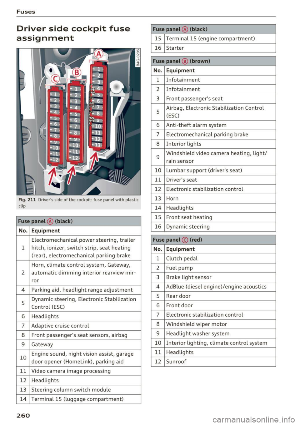
Driver side cockpit fuse
assignment
F ig. 211 Driver 's side of t he cockpit : fuse pa nel w it h plastic
clip
Fuse panel @ (black )
No . Equipment
Electromecha nica l powe r stee ring, trai ler
1 hitch, io nizer, sw itch st rip, sea t heat ing
(rear), ele ctromech an ical parking br ake
Horn, climate control system, Gateway,
2 automatic dimming interior rearv
iew mir-
ror
4 Parking aid, headlight range adjustment
5 Dynamic steering, Electron
ic Stabilization
Control (ESC)
6 Headlights
7 Adaptive cru ise control
8 Front passenger's seat senso rs, airbag
9 Gateway
1 0 E
ngine sound, night vision ass ist, garage
door opener (Homelink), parking aid
1 1 Video camera im age pro cessing
12 Headlights
1 3 Steeri ng col umn sw itch module
14 Term inal 15 ( luggage compartment)
260
Fuse panel @ (black)
15 Terminal 15 (engine compartment)
16 Starte r
Fuse panel @ (brown )
No. Equipment
1 Infotainment
2 Infotainmen t
3 F
ront passenger's seat
5 A
irbag, Elect ronic S tabiliza tion Con trol
( E SC)
6 Ant i- theft alarm system
7 Electromechanical pa rking brake
8 Inter io r li ghts
9
Windshie ld video camera heating, light/
rain sensor
10 Lumbar support (dr iver's seat)
11 Driver's seat
12 Elec tronic stab ilizati on con trol
13 Horn
1 4 H eadlights
15 Front seat heating
16 Dynamic stee ring
Fuse panel © (red)
No . Equipment
1 C lutch peda l
2 Fuel pump
3 Brake light sensor
4 AdB
lue (diese l eng ine)/engine aco ustics
5 Rear door
6 Fr
ont door
7 Electronic stab ili z at ion con trol
8 Windshie ld wiper motor
9 Headlight washer system
10 Inter
ior lig hting, climate control system
1 1 Headlights
12 Sunroof
Page 263 of 294
..... N
0 CJ '
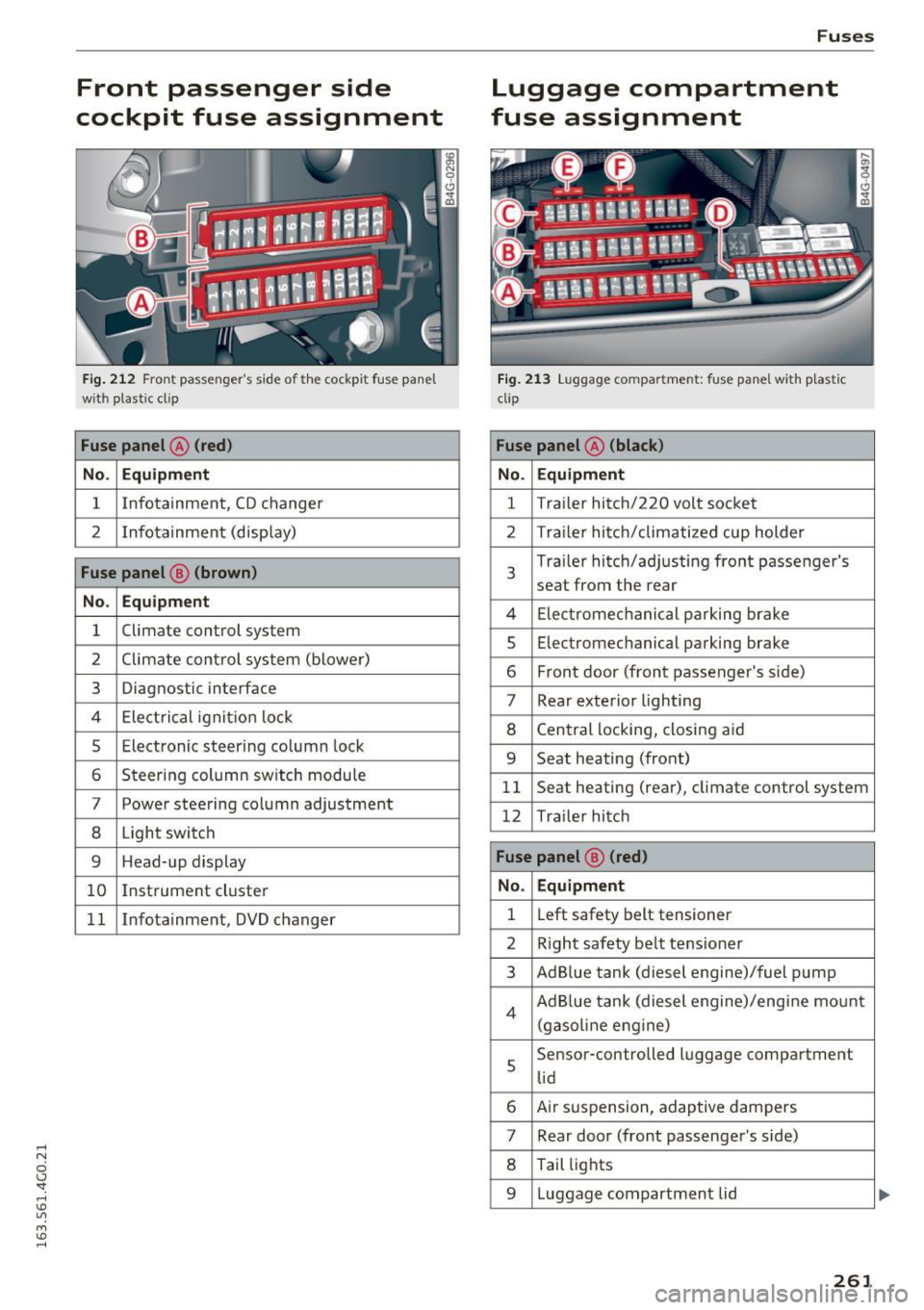
Front passenger side
cockpit fuse assignment
Fig. 212 Front passenger's sid e of t he cockpit fuse pane l
with plastic cl ip
Fuse panel @ (red)
No. Equipment
1 Infotainment, CD changer
2 Infotainment
(display)
Fuse panel@ (brown)
No . Equipment
1 Climate
control system
2 Climate control
system (blower)
3 Diagnostic interface
4 Electrical ignition lock
5 Electronic steering column lock
6 Steering column sw itch module
7 Power steering column adjustment
8 Light switch
9 Head-up display
10 I
nst rument cluster
1 1 Infotainment, DVD changer
Fuses
Luggage compartment
fuse assignment
Fig. 213 Luggage compartment: fuse panel with plastic
clip
Fuse panel @ (black )
No. Equipment
1 Tra
iler hitch/220 volt socket
2 Tra ile r hitch/climatized cup holder
3
Tra iler hitch/adjusting front passenger's
seat from the rear
4 Elec trom echan ica l parking brake
5 Electromec hanical parking brake
6 Front door (front passenger's side)
7 Rear exterior lighting
8 Central locking, closing aid
9 Seat heating (front)
1 1 Seat heating
(rear), climate control system
12 Tra iler hitch
Fuse panel @ (red)
No . Equipment
1 Left
safety belt tensioner
2 R ight safety belt tensioner
3 Ad Blue tank (diesel engine)/fuel pump
4 Ad Blue tank (diesel engine)/engine mount
(gasoline eng ine)
s
Sensor-controlled luggage compartment
lid
6 Air suspension, adaptive dampers
7 Rear door (front passenger's side)
8 Tail lights
9 Luggage compartmen t lid
261
Page 264 of 294
Fuses
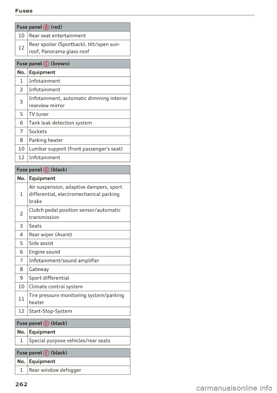
Fuse panel@ (red )
10 Rear seat enterta inment
12
Rea r spo ile r (Sportbac k), t ilt/open sun-
roof, P anorama glass roof
Fuse panel © (brown)
No . Equipment
1 Infotainment
2 In fota inment
3
Infotainment , automatic d imm ing inter ior
rearv iew mir ror
s TV t uner
6 Tank leak detect io n system
7 Sockets
8 Par king heater
10 Lumba r su pport (front passenger's seat)
12 Infota inme nt
Fuse panel @ (black)
No . Equipment
Air suspens ion, adapt ive dampers, sport
l different ial, ele ctromechanical parking
brake
2 Clu tch pedal position senso r/automatic
transmission
3 Sea ts
4 Rear wiper (Avant)
s Side ass ist
6 E ngine sound
7 Info ta inment/so und amplifie r
8 Gateway
9 Sport differen tial
10 Climate cont rol system
11
T ire pressu re moni to ring sys te m /par king
he ater
12 Sta rt-Stop-System
Fuse panel © (black)
No . Equipment
1 Special p urpose vehicles/ rear seats
Fuse panel ® (black)
No. Equipment
1 Rear window de fogger
262
Page 267 of 294
.... N
0 CJ '
When jump starting or charging the battery,
never connect the negative ground cable to
the battery negative post because the battery
manager system must be able to detect the
battery's state of charge . Always connect the
negative ground cable to the negat ive ground
post of the battery manager control unit .
Use of jumper cables
Make sure to connect the jumper cable clamps in
exactly the order described below!
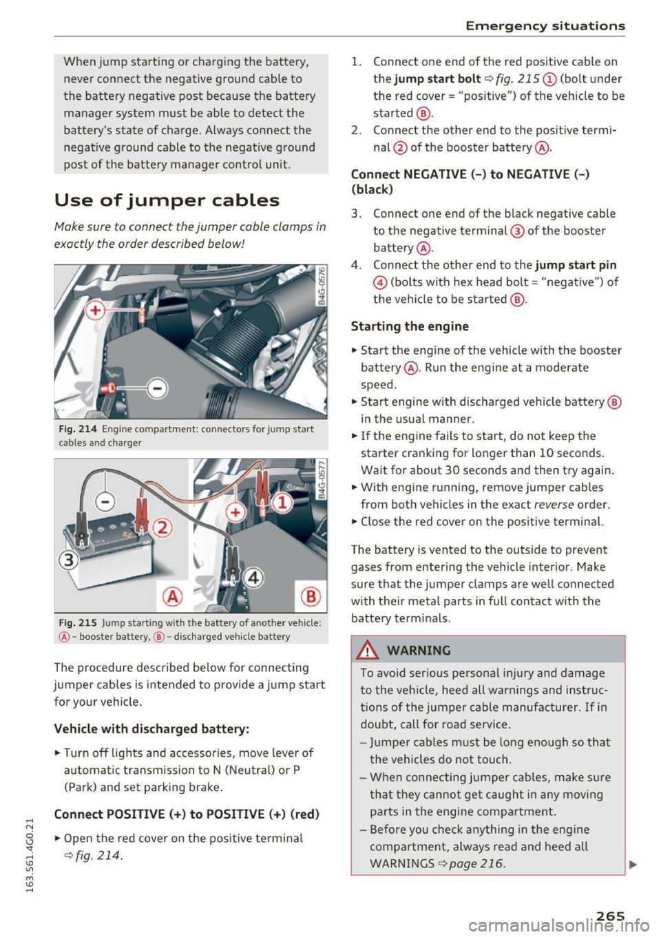
Fig. 214 Engine compa rtment: connec tor s for ju mp start
cables and cha rger
@
Fig. 215 Jump start ing with the battery of another vehicle:
@ -booste r battery ,@ -discharged vehicle battery
The procedure described below for connecting
jumper cables is intended to provide a jump start
for your vehicle.
Vehicle with discharged battery:
.. Turn off lights and accessories, move lever of
automatic transmission to N (Neutral) or P
(Park) and set parking brake .
Connect POSITIVE(+) to POSITIVE(+) (red)
.,. Open the red cover on the positive terminal
~fig. 214 .
Emergency situations
1. Connect one end of the red positive cab le on
the
jump start bolt~ fig. 215 (D (bolt under
the red cover = "posit ive") of the veh icle to be
started @.
2. Connect the other end to the posit ive termi-
nal @of the booster battery @.
Connect NEGATIVE (-) to NEGATIVE (- )
(black)
3. Connect one end of the black negative cable
to the negative terminal @ of the booster
battery @.
4 . Connect the other end to the
jump start pin
@ (bolts with hex head bolt= "negat ive") of
the vehicle to be started @.
Starting the engine
.. Start the engine of the vehicle with the booster
battery @. Run the eng ine at a moderate
speed .
.,. Start engine w ith discharged vehicle battery @
in the usual manner.
.,. If the engine fails to start, do not keep the
starter cranking for longer than 10 seconds.
Wait for about 30 seconds and then try again .
.. With engine running, remove jumper cables
from both vehicles in the exact
reverse order .
.. Close the red cover on the positive terminal.
The battery is vented to the outside to prevent gases from entering the vehicle interior . Make
sure that the jumper clamps are well connected
with their metal parts in full contact with the
battery term inals .
A WARNING
To avoid ser ious personal injury and damage
to the vehicle, heed all warnings and instruc
tions of the jumper cable manufacturer.
If in
doubt, call for road service.
- Jumpe r cables must be long enough so that
the vehicles do not touch .
- When connecting jumper cables, make su re
that they cannot get caug ht in any moving
parts in the engine compartment.
- Before you check anything in the engine
compa rtment, always read and heed all
WARNINGS
~page 216.
265
Page 272 of 294
Technical data
Technical data
Vehicle identification
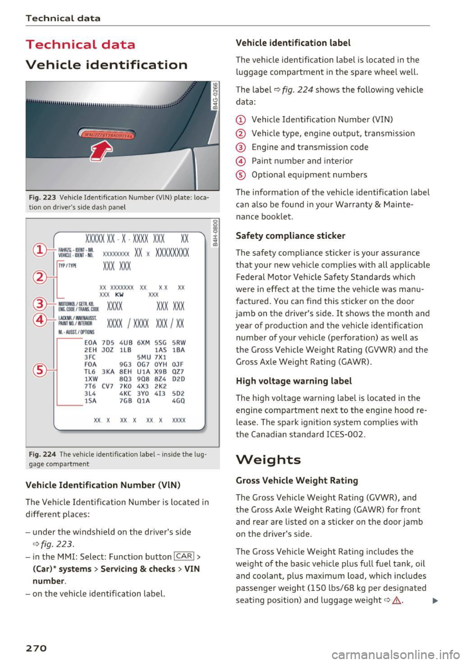
Fig. 223 Vehicle Ident if ication Numbe r (VlN) plate : loca·
tio n on d river 's side dash panel
XXXXX XX -X -XX XX XXX XX
@-+ ~J:~t::1 ::: xxxxxxxx xx x xxxx xxx x
IYP lf'VPE XXX X XX
XX XXXXXXX XX X X XX
XXX KW XXX
\YT IM:.COll/fAANS ,COOE XXX XXX 15\_L I MOIOlll
@-+ ~~
1
:tr:~i XXXX I XXXX XXX I XX
II. -AUSST. / OPTIO NS
E0 A 7D5 4UB 6X
M SSG SR W
2EH JOZ lLB lAS
lBA
3FC SM U 7 X1
F0 A
9G3 0
G7 0Y H
0JF
TL 6 3 KA 8EH UlA X 9B Q
Z7
1 XW
803 908
824 020
7T6 C V7 7 K0 4X3 2K2
3L4 4KC 3Y0 413
502
lS A 7GB 01A
4G0
XX X XX X
XX X xxxx
Fig. 224 The vehicle ide ntifi cat ion l abel - inside t he lug ·
gage compartment
Vehicle Identification Number (VlN)
The Vehicle Identification Number is located in
different places :
- under the windshield on the driver's side
¢fig . 223.
- in the MMI: Select: Function button ICAR I >
(Car)* systems > Servicing & checks > VIN
number .
-on the vehicle identification label.
270
Vehicle identification label
The vehicle identification label is located in the
luggage compartment in the spare wheel we ll.
The label
9 fig. 224 shows the following vehicle
data:
(D Vehicle Identif ication Number (VIN)
@ Vehicle type, engine output, transmission
@ Engine and transmission code
@ Paint number and interior
® Optional equipment numbers
The information of the vehicle identification label
can also be found in your Warranty
& Mainte ·
nance booklet.
Safety compliance sticker
The safety compliance sticker is your assurance
that your new veh icle complies with all applicable
Federal Motor Vehicle Safety Standards which
were in effect at the time the vehicle was manu
factured. You can find this sticker on the door
jamb on the driver's side. It shows the month and
year of production and the vehicle identification
number of your vehicle (perforation) as well as
the Gross Vehicle Weight Rating (GVWR) and the Gross Axle We ight Rating (GAWR).
High voltage warning label
The high voltage warning label is located in the
engine compartment next to the engine hood re
lease. The spark ignition system complies w ith
the Canadian standard ICES-002.
Weights
Gross Vehicle Weight Rating
The Gross Vehicle Weight Rating (GVWR), and
the Gross Axle Weight Rating (GAWR) for front
and rear are listed on a sticker on the door jamb
on the driver 's side.
The Gross Vehicle Weight Rating includes the
weight of the basic vehicle plus full fuel tank, oil
and coolant, plus maximum load, which includes
passenger weight (150 lbs/68 kg per designated
seat ing position) and luggage weight¢,&. .
1111>
Page 277 of 294
@ For the sake of the environment
-Changing the engine settings will adversely
affect emission levels. This is detrimental to
the environment and increases fuel con
sumption.
- Always observe environmental regulations
when disposing of old engine oil, used brake
fluid, dirty engine coolant, spent batteries
or worn out tires .
- Undeployed airbag modules and pretension
ers might be classified as Perchlorate Mate
rial -special handling may apply, see
www .dtsc.ca.gov/hazardouswaste/perchlo
rate . When the vehicle or parts of the re
straint system including airbag modules
safety belts with pretensioners are scrap
ped, all applicable laws and regulations
must be observed. Your authorized Audi
dealer is familiar with these requirements
and we recommend that you have your deal er perform this service for you.
Accessories and
technical changes
Additional accessories and parts replacement
Always consult an authori zed Audi dealer before
purchasing accessories.
Your vehicle incorporates the latest safety design
features ensuring a high standard of active and passive safety.
Th is safety could be compromised by non-ap
proved changes to the vehicle. For this reason, if
parts have to be replaced, please observe the fol
lowing points when installing additional accesso
ries :
Approved Audi accessories and genuine Audi parts are available from authorized Audi dealers.
These dealers also have the necessary facilities, tools and trained specialists to install the parts
,...., and accessories properly .
N
0 <.J 'SI: ,....,
A WARNING
Using the wrong spare parts or using non-ap
proved accessories can cause damage to the
vehicle and serious personal injury.
- Use only accessories expressly approved by
Audi and genuine Audi spare parts
- These parts and accessories have been spe
cially designed to be used on your vehicle.
- Never install accessories such as telephone
cradles or beverage holders on airbag covers
or within the airbag deployment zones . Do
ing so will increase the risk of injury if air
bags are triggered in an accident!
- Before you check anything in the engine
compartment, always read and heed all
WARNINGS 9page 216.
(D Note
-If items other than genuine Audi spare
parts, add-on equipment and accessory
items are used or if repair work is not per
formed according to specified methods, this
can result in severe damage to your vehi
cle's engine and body (such as corrosion)
and adversely affect your vehicle's warranty.
- If emergency repairs must be performed
elsewhere, have the vehicle examined by an
authorized Audi dealer as soon as possible.
- The manufacturer cannot be held liable for
damage which occurs due to failure to com
ply with these stipulations.
Technical Modifications
Our guid elines must be complied with when t ech
nical modifications are made.
Always consult an authorized Audi dealer
before
starting work on any modifications.
This will help ensure that vehicle function, per
formance and safety are not impaired
9 ,& .
Attempting to work on electronic components
and the software used with them can cause mal
functions. Because of the way electronic compo
nents are interconnected with each other, such
malfunctions can also have an adverse affect on
other systems that are not directly involved. This .,._
275
Page 278 of 294
Consumer inf orm ation
means t hat yo u risk both a substantia l reduction
in the operational safety of your vehicle and an
increased wear of veh icle parts ~&. .
Author ized Audi dealers w ill perform this work in
a professional and competent manner or, in spe
cial cases, refer you to a professional company
that spec ializes in such modif icat ions.
A WARNING
Improper repairs and modifications can
change the way vehicle systems work and
cause damage to the veh icle and ser ious per
sonal injury.
([) Note
If emergency repa irs must be performed else
where, have the vehicle examined by an au thorized Audi dealer as soon as possib le.
Declaration of
Compliance, Telecom munication and
Electronic Systems
Radio Frequency Devices and Radiocommunica
tion Equipment User Manual Notice.
The manufacturer is not responsible for any radio
or TV interference caused by unauthor ized modi
fications to this equ ipment .
Devices
The fo llow ing devices each comp ly w ith FCC Part
15.19, FCC 15.21 and RSS-Gen Issue
1:
- Adaptive cruise contro l*
- Audi s ide ass ist*
- Cell phone package*
- Convenie nce key*
- Electronic immobilizer
- Garage door opener (Homelink)*
- Remote control key
FCC Part 15.19
This device comp lies wit h pa rt 15 of the FCC
Rules. Operat ion is s ubject to the following two
conditions:
276
(1) This dev ice may not cause ha rmf ul interfer
ence, and
( 2 ) this devi ce must accep t any i nte rference re
ce ived, in cl ud ing in terference tha t may c ause un
desired ope ration.
FCC Part 15.21
CAUTION :
Changes or modificat ions not express ly approved
by the pa rty responsible for compliance could
vo id the user's a uthority to operate t he equ ip
ment .
RSS-Gen Issue 1
Operat ion is subject to the following two cond i
tions:
(1) this device may not ca use interference, and
(2) this devi ce must accep t any inte rference, in
cl ud ing interfe rence that may cause undesi red
operation of the device.