automatic transmission AUDI A6 2017 Owners Manual
[x] Cancel search | Manufacturer: AUDI, Model Year: 2017, Model line: A6, Model: AUDI A6 2017Pages: 280, PDF Size: 70.24 MB
Page 4 of 280
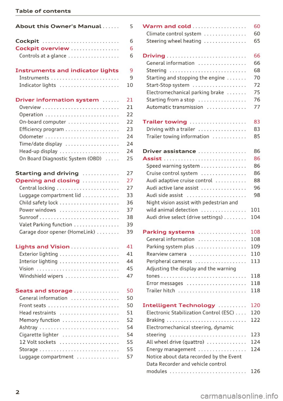
Table of contents
About this Owner's Manual ... .. .
Cockpit ... .. ............... .... .. .
Cockpit overview ................ .
Controls at a glance ... .......... .. .. .
Instruments and indicator lights
Instruments .... ... .......... .. .. .. .
Indicator lights .. .. .......... .. .. .. .
Driver information system ... .. .
Overview ... .... ... .......... ...... .
Operation .... .. ... .......... .. .. .. .
On-board computer ........... .... .. .
Eff iciency program . ........... .. .. .. .
Odometer .. .. .. ............ .... ... .
T ime/date display ........... .... ... .
He ad-up display .... .. .. ..... ... .. .. .
On Board Diagnostic System (OBD) .. .. .
Starting and driving ...... .. .. .. .
Opening and closing .......... .. .
Central locking ... ............ .... .. .
L uggage compartment lid ...... .... .. .
Child safety lock .... .......... .. .. .. .
Power windows ...... ..... ... .. .. .. .
Sunroof . ... .... .. ........... .. .. .. . 5
6
6
6
9
9
10
2 1
21
22
22
23
24
24
24
25
27
27
27
33
36
37
38
Valet Parking function . . . . . . . . . . . . . . . . 39
Garage door opener (Home link) . . . . . . . . 39
Lights and Vision . . . . . . . . . . . . . . . . . 41
Exterior lighting . . . . . . . . . . . . . . . . . . . . . 41
Interior lighting . . . . . . . . . . . . . . . . . . . . . 44
V1s1on . . . . . . . . . . . . . . . . . . . . . . . . . . . . . 45
Windshield wipers . . . . . . . . . . . . . . . . . . . 47
S eats and storage . . . . . . . . . . . . . . . . 50
Gene ral information . . . . . . . . . . . . . . . . . 50
Fro nt seats . . . . . . . . . . . . . . . . . . . . . . . . . 50
H ead restraints . . . . . . . . . . . . . . . . . . . . .
51
Memory function . . . . . . . . . . . . . . . . . . . . 52
Ashtray . . . . . . . . . . . . . . . . . . . . . . . . . . . . 54
Cigarette lighter . . . . . . . . . . . . . . . . . . . . 54
12 Volt sockets . . . . . . . . . . . . . . . . . . . . . 55
Storage . . . . . . . . . . . . . . . . . . . . . . . . . . . . 55
Luggage compartment . . . . . . . . . . . . . . . 57
2
Warm and cold .. .. ... .......... . .
Climate contro l system . ............ . .
Steering wheel heating .. . .......... . .
Driving ..... .. .. .. .. ... .......... . .
General information . .... .......... . .
Steering .. .. .. .. .. .. ............. . .
Start ing and stopping the eng ine ..... . .
Start-Stop system .. .. ... .. ..... ... . .
E le ctromechanical parking brake ..... . .
Start ing from a stop .. .............. .
Automatic transmission
Trailer towing ..... .............. .
Driving with a trailer .. ... .. ... ... .. . .
T ra iler towing information .......... . .
Driver assistance .. ........ ..... . .
Assist ...... .. .. .. .. .. ........... . .
Speed warning system . ............. . .
Cruise control system ... ........... . .
Audi adaptive c ruise contro l .......... .
Audi active lane assist ... ........... . .
Audi s ide ass ist .. .. .. ............. . .
Night vision assist w ith pedestrian and
wild animal detection ............... .
Audi drive select (drive settings) ....... .
60
60
65
66
66
68
70
72
75
76
77
83
83
85
86
86
86
86
88
96
98
101
104
Park ing systems . . . . . . . . . . . . . . . . . 108
Genera l information . . . . . . . . . . . . . . . . . 108
Parking system plus . . . . . . . . . . . . . . . . . . 109
Rearviewcamera . ......... ....... ... 110
Peripheral cameras . . . . . . . . . . . . . . . . . . 113
Adjus ting the display and the warning
tones..............................
118
Error messages . . . . . . . . . . . . . . . . . . . . . 118
Trailer hitch . . . . . . . . . . . . . . . . . . . . . . . . 118
Intelligent Technology . . . . . . . . . . 120
E lectronic Stabilization Control (ESC) . . . . 120
B raking . . . . . . . . . . . . . . . . . . . . . . . . . . . . 122
E lectromechanical steering, dynamic
steering . . . . . . . . . . . . . . . . . . . . . . . . . . .
123
All wheel drive (quattro) . . . . . . . . . . . . . . 124
Energy management . . . . . . . . . . . . . . . . . 124
Notice about data recorded by the Event
Data Recorder and vehicle control
modules . . . . . . . . . . . . . . . . . . . . . . . . . . .
126
Page 79 of 280
co
co
.... N
" N .... 0 0 <.,;) 'SI"
-Hill hold assist cannot hold the veh icle in
place on all h ills (for example, if the ground
is slippery or icy).
- To reduce the risk of an accident, always
make sure the vehicle is situated safely
wh ile stat io nary.
Automatic transmission
Introduction
The automat ic transmission is cont rolled e lec
tron ica lly. The tra nsmission shifts up or down au
tomatically depending on which drive program is
selected.
When a
moderat e driving style is used, the
transmission selects the most economical driving mode. The t ransmission upshifts at a lower RPM
and downshifts at a higher RPM to improve fuel
efficiency .
The transmission sw itches to a sporty mode a fter
a kick-down or when the driver uses a
s po rt y
driving st yle
characterized by quick accelerator
pedal movements, heavy acce leration, frequent
changes in speed and traveling at the maximum
speed .
If desired, the driver can also select the gears
manually ( tiptronic mode) q page 80 .
Appl ies to : ve hicles w ith S tro nic t ran smi ssio n
The 5 tronic is a dual-clutch transmiss ion . Powe r
is transferred using two cl utches that work inde
pendently from one another. They replace the
torque converter used in conventional automat ic
transmissions and allow the vehicle to accelerate
without a noticeab le interruption in tract ion.
A ppl ies to: ve hicles with a t iptro nic tr ansmi ssio n
Power is transfer red using a torque conver ter.
D rivi ng
Selector lever positions
Fig. 83 Instrument cl uster: selector leve r pos itions
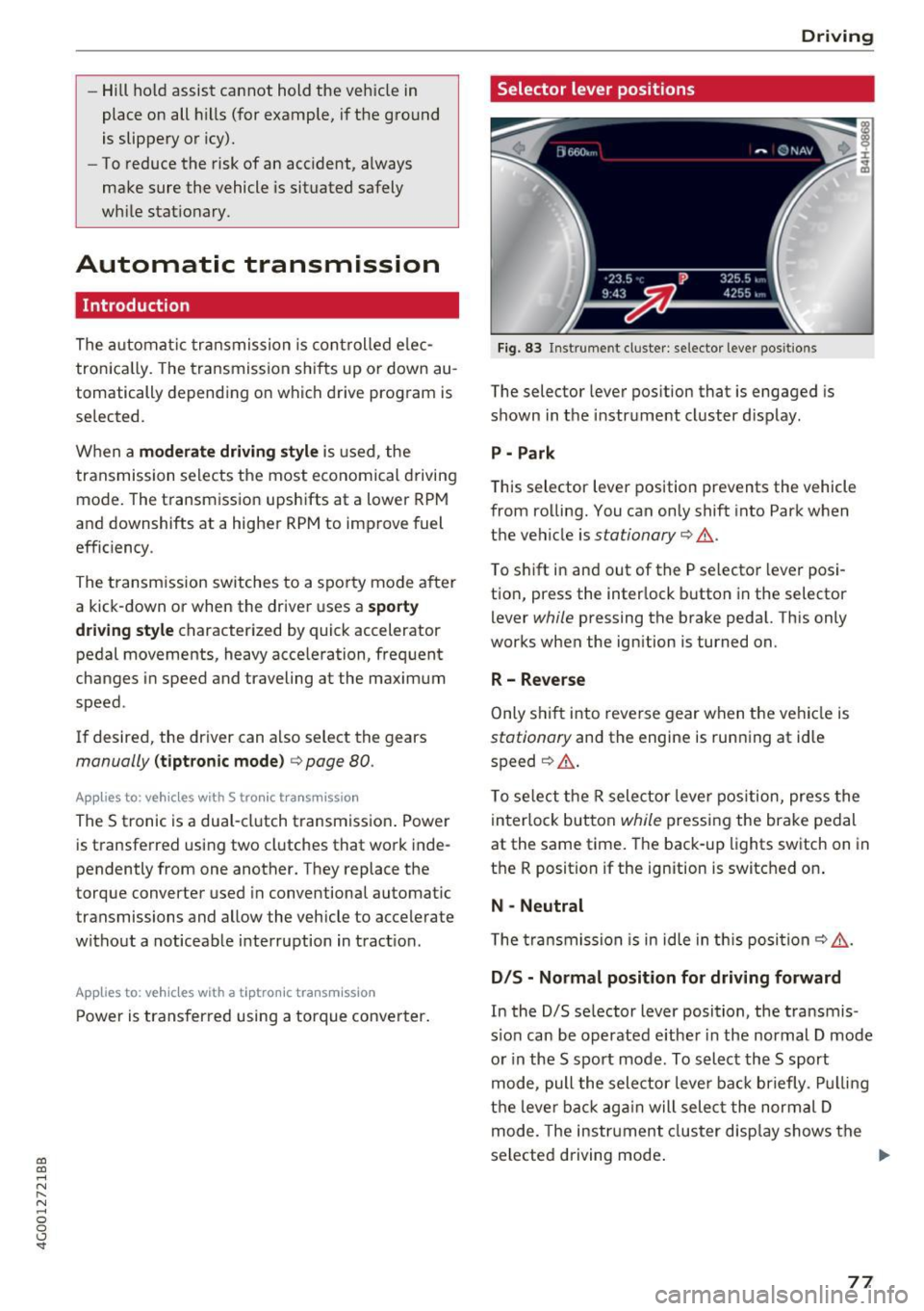
The selector lever position that is engaged is
shown in the instrume nt cluster display .
P - Park
This selector lever position prevents the vehicle
from rolling. You can only shift into Park when
the vehicle is
stationary q &. .
To shift in and out of the P selector lever posi
tio n, press the inter lock b utton in the selector
lever
while pressing the brake peda l. Th is only
works when the ign ition is turned on.
R- Reverse
Only s hift into reve rse gear when t he vehicle is
stationary and the engine is running at idle
speed
q &. .
To se lect the R selector leve r pos ition, press the
in terlo ck button
while pressing the brake pedal
at the same time. The back-up lights switch on in
the R position if the ignition is switched on .
N -Neutral
T he tra ns m ission is in idle in th is posi tion
q &_ .
DIS -Normal position for driving forward
In the D/S se lector lever position, the t ransmis
s io n can be operated e ither in the normal D mode
or in the 5 spo rt mode . To select the 5 sport
mode, pull the selector leve r ba ck briefly . Pu llin g
t h e lever ba ck aga in will selec t the normal D
mode. The instr ument cluster disp lay shows the
selected driving mode .
77
Page 80 of 280
Driving
In the normal mode D, the transmission auto
matically selects the suitable gear ratio. It de
pends on engine load, vehicle speed and driving
style.
Select the
spo rt mode S for sporty driving. The
vehicle makes full use of the engine 's power.
Shifting is more noticeable when accelerating.
To move from selector lever position N to D, you must press the brake pedal and the vehicle must
be traveling less than 1 mph (2 km/h) or be sta
tionary
~ & .
A WARNING
-The vehicle can roll even if the ignition is
switched off .
- Never select R or P while driving, because this increases the risk of an accident.
-
- Power is still transmitted to the wheels
when the engine is running at idle. To pre
vent the vehicle from "creeping", you must keep your foot on the brake in all selector
lever positions (except P) when the engine is
running . Otherwise , this increases the risk
of an accident.
- Do not inadvertently press the accelerator
pedal when the vehicle is stopped if a gear is
engaged. Otherwise the vehicle will start to
move immediately, even if the parking brake
is set. This could result in a crash.
- To decrease the risk of an accident, these
lector lever must be in the P position and
the parking brake must be set before open
ing the hood and working on a running en
gine. Always read and follow the applicable
warnings
q page 198, Working in the en
gine compartment.
(D Tips
- Drive select: sporty shifting characteristics
can be selected using the
Dynamic driving
mode .Swill appear in the instrument clus
ter display instead of D.
- If you accidentally select N while driving, take your foot off the accelerator pedal and
wait for the engine to slow down to idle be
fore selecting D/S.
78
- If there is a power failure, the selector lever
will not move out of the P position. The
emergency release can be used if this hap
pens
q page 82 .
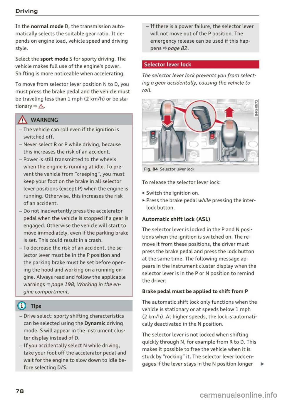
Selector lever lock
The selector lever lock prevents you from select
ing a gear accidentally, causing the vehicle to
roll .
Fig. 84 Selecto r lever lock
To release the selector lever lock :
.,. Switch the ignition on .
)
.,. Press the brake pedal while pressing the inter-
lock button.
Automatic shift lock (ASL)
The selector lever is locked in the P and N posi
tions when the ignition is switched on. The re
move it from these positions , the driver must
press the brake pedal and press the lock button
at the same time . The following message ap
pears in the instrument cluster display when the
selector lever is in the P or N position to remind
the driver:
Brake pedal must be applied to shift from P
The automatic shift lock only functions when the
vehicle is stationary or at speeds below 1 mph
(2 km/h) . At higher speeds, the lock is automati
cally deactivated in the N position .
The selector lever is not locked when shifting
quickly through N, for example from R to D. This
makes it possible to free the vehicle when it is
stuck by "rocking " it. The selector lever lock en-
gages if the lever stays in the N position longer .,..
Page 81 of 280
co
co
.... N
" N .... 0 0 <..:l -
pressed.
Interlock button
The in terlo ck button i n the selector lever handle
p revents yo u from moving the selector lever i n
advertently while in some se lector lever posi
tions. The positions that require the interlock button to be pressed are marked in co lor i n the il
lustration
c:> fig . 84.
Driving tips
Starting the engine
.. The selector lever must be in the P or the N po
s it ion.
Starting from a stop
.. Press and hold the brake pedal.
.. Press and hold the lock button in the selector
lever hand le, select the desired se lector lever
pos ition such as 0/5 and release the lock but
ton .
.. Wait a moment unt il the transm ission shifts .
You w ill no tice a slight movement when t he
gear e ngages .
.. Release t he b rake pedal and press the acce le ra
tor pedal
c:> &_ .
Stopping temporarily
.. Keep the veh icle stat ionary using the braking
peda l, for example at traffic lights .
.. Do no t press t he accelerator pedal when doing
t hi s.
.. To p revent the vehicle from rolling when yo u
sta rt driving, se t the park ing brake when stop
ping on steep i nclines
c:> _&. .
.. The parking bra ke wi ll re lease automatically
and the vehicle will start moving once you press
the accelerator pedal.
Stopping /parking
If the se lec to r l ever is not in the P posi tion when
you open the driver's door, the vehicle could rol l.
The message
Transmission: selector lever in
drive position!
appears . A warn ing tone wi ll also
sound.
.. Press and hold the brake pedal
c:> _&. .
Driving
.. Se t the par king brake.
.. Select the P selector lever posit ion .
U nder certain circumst ances, su ch as driving in
t h e mo unta ins, i t may be useful to swi tch tempo
ra rily to the manual s hift program in order to
man ua lly adjust the gea rs to the driving condi
tions
c:> poge 80.
On inclines, activate the parking brake fi rs t a nd
t h en move the selector lever to t he P position
c:> page 75. This prevents the locking mechanism
from be ing loaded too heavily and will make it
easier to move the selector lever out of the P po
s ition .
A WARNING
- The vehicle ca n roll even if the ignit ion is
sw itched off .
- Never leave your ve hicle w ith the engine
r u nning while in gear .
- Do not press the acce le rator peda l when
changing the se lector lever posi tion while
the vehicle is s ta tionary and the engi ne is
r u nning .
-
-Please no te that a small amo unt of power is
transmi tted if the veh icle is stopped tern po
r a rily w hile in t he D/S or R select or leve r po
si tion. To reduce t he risk of an a cc iden t, y ou
m ust cont in ue pressing firmly on the brake
pedal whi le t he veh icle is stoppe d so that i t
does not ro ll.
- Never engage the R or P sele ctor leve l pos i
tions while dr iv ing. It could ca use a crash .
- Before driving down a steep slope, reduce
your speed and sh ift into a lowe r gear w ith
"t i pt ronic" .
- Do not r ide the brakes or p ress the brake
pedal too often or too lon g when dr iving
downhill . Constant bra king causes the
brakes to overheat and s ubstant ially re
duces brak ing performance, increases b rak
ing d istance or causes comp lete fai lure of
the bra ke system.
- If you must stop on an incline, a lways hold
the vehicle in place wit h the foot brake or
pa rking bra ke to p reve nt i t from rolling
back.
79
Page 82 of 280
Driving
-Never hold the vehicle on an incline with a
slipping clutch. The clutch opens automati
cally when it becomes too hot from the
overload . The
[i1 indicator Light turns on
and a message appears~
page 81 when
the clutch is overloaded.
(D Note
-When stopping on an incline, do not try to
hold the vehicle in place by pressing the ac
celerator pedal while a driving gear is se
lected. This can cause the transmission to
overheat and can damage it. Set the parking brake or press the brake pedal to prevent
the vehicle from rolling.
- Allowing the vehicle to roll when the engine
is stopped will damage the transmission be
cause it is not lubricated .
@ Tips
For safety reasons, the parking brake is re
leased automatically only when the driver's
safety belt is fastened.
Hill descent control
The hill descent control system assists the driver
when driving down hills .
Hill descent control is activated when the selec
tor lever is in the Dor S position and you press
the brake pedal. The transmission automatically
selects a gear that is suitable for the hill . Hill de
scent control tries to maintain the speed ach
ieved at the time of braking, within physical and
technical limitations. If may still be necessary to
adjust the speed with the brake pedal.
Hill descent control switches off once the hill lev
els out or you press the accelerator pedal.
On vehicles with a cruise control system*
~ page 86, hill descent control is also activated
when the speed is set.
A WARNING
Hill descent control cannot overcome physical
limitations , so it may not be able to maintain
80
a constant speed under all conditions. Always
be ready to apply the brakes .
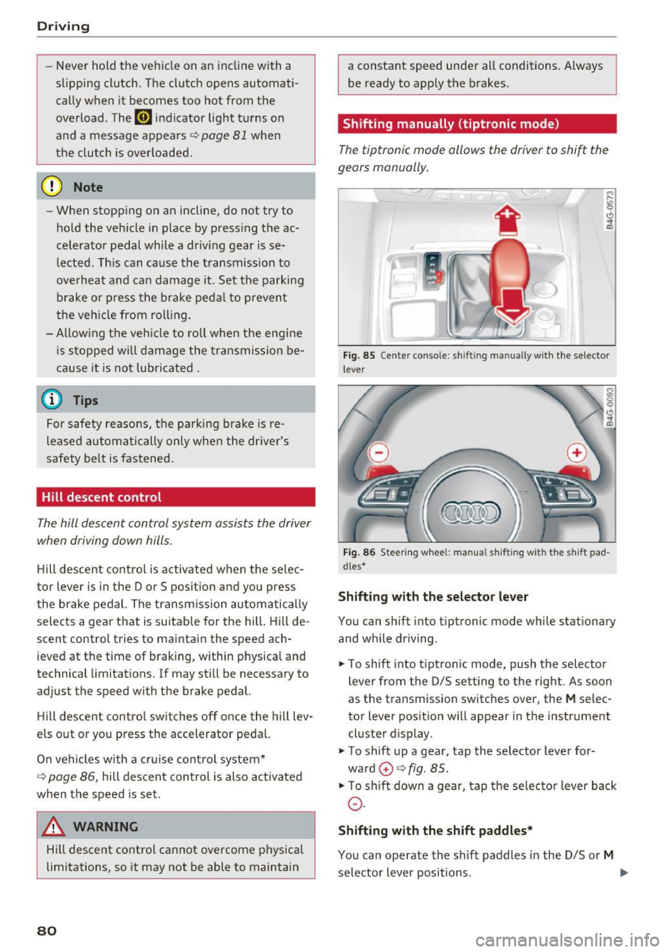
Shifting manually (tiptronic mode)
The tiptronic mode allows the driver to shift the
gears manually.
'
}
Fig . 85 Center console: sh ift ing manually with the selector
l ever
Fig. 86 Steering wheel : manual s hift ing with the s hift pad
dles*
Shifting with the selector lever
You can shift into tip tron ic mode while stationary
and while driving.
.,. To shift into tiptronic mode, push the selector
lever from the D/S setting to the right. As soon
as the transmission switches over, the
M selec
tor lever position will appear in the instrument
cluster display .
.,. To shift up a gear, tap the selector lever for
ward
0 ~ fig. 85.
.,. To shift down a gear, tap the selector lever back
0-
Shifting with the shift paddles*
You can operate the shift paddles in the D/S or M
selector lever positions. ..,.
Page 83 of 280
co
co
.... N
" N .... 0 0 <..:l '
¢fig. 86.
~ To shift down one gear, tap the 0 shift paddle.
The transmission automatically shifts up or down before critical engine speed is reached.
The transmission only allows manual shifting
when the engine speed is within the permitted
range.
Kick-down
Kick-down enables maximum acceleration.
When you press the accelerator pedal down be
yond the resistance point, the automatic trans
mission downshifts into a lower gear, depending
on vehicle speed and engine RPM.
It shifts up in
to the next higher gear once the maximum speci
fied engine RPM is reached.
A WARNING
Please note that the wheels could spin on
slick or slippery roads when kick-down is ac
tive.
Launch control program
A ppl ies to: ve hicles wit h S tro nic
-
The launch control program provides the best
possible acceleration when starting from a stop.
Requirement: the engine must be at operating
temperature and the steering wheel must not be
turned .
~ Deactivate the Start/Stop system*¢ page 74.
The LED in the l0 u•I button turns on.
~ Switch the Electronic Stabilization Control
(ESC) sport mode on ¢
page 121. The II i ndi
cator light turns on.
~ Pull the selector lever back out of the D/S posi
tion briefly to select the S position or select the
DYNAMIC driving mode in drive select
¢page 106.
~ Press the brake pedal firmly with your left foot
and hold it all the way down for at least one
second .
Driving
~ At the same time, press the gas pedal all the
way down with your right foot until the engine reaches and stays at a high RPM level.
~ Remove your foot from the brake pedal within
five seconds ¢_& .
A WARNING
-Always adapt your driving to the traffic flow.
- Only use the Launch control program when
road and traffic conditions allow it and oth
er drivers will not be endangered or both
ered by your driving and the vehicle's accel
eration.
- Please note that the drive wheels can spin
and the vehicle can break away when sport
mode is switched on, especially when the
road is slippery.
- Once the vehicle has started moving, press
the
I.P-O FFI button briefly to turn the sport
mode off.
@ Tips
- The transmission temperature may increase
significantly after using the launch control
program. If that happens, the program may
not be available for a few minutes.
It will be
available again after a cool-down period.
- When accelerating using the launch control
program, all vehicle parts are subject to
heavy loads. This can lead to increased
wear.
Transmission malfunction
DD Transmission: please press brake pedal and
select gear again
Press the brake pedal and select the desired se
lector lever position again. You can then continue
driving.
DD Transmission overheating: Please drive con
servatively.
The transmission temperature has increased sig
nificantly due to the sporty driving manner. Drive
in a less sporty manner until the temperature re
turns to the normal range and the indicator light switches of. .,..
81
Page 239 of 280
co
co
.... N
" N .... 0 0 <..:l '
The vehicle jack* in your vehicle is mainte
nance-free.
Replacing wheels
Before changing a wheel
Observe the following precautions for your own
and your passenger's safety when changing a
wheel .
.,. After you experience a tire failure, pull the car
well away from moving traffic and try to reach
level ground before you stop¢,&. .
.,. All passengers should
leave the car and move
to a safe location (for instance, beh ind the
guardrail)¢ ,&..
.. Engage the
parking brake to prevent your vehi
cle from rolling unintentionally ¢,&. .
.. Move
selector lever to position P ¢ ,&. .
.,. If you are towing a trailer, unhitch the trailer
from your vehicle.
.,. Take the
jack and the spare tire* out of the lug
gage compartment c:> page 236.
A WARNING
You or your passengers could be inju red wh ile
changing a wheel if you do not follow these
safety precautions:
- If you have a flat tire, move a safe distance
off the road. Turn off the engine, turn the
emergency flashers on and use other warn
ing devices to alert other motorists .
- Make sure that passengers wait in a safe
place away from the vehicle and well away
from the road and traffic.
- T o help prevent the vehicle from moving
sudden ly and possibly slipping off the jack,
always fully set the parking brake and block
the wheel diagonally opposite the wheel be ing changed. When one front wheel is lifted
off the ground, plac ing the Automatic
Transmission in P (Park) will
not prevent the
vehicle from mov ing.
- Before you change a wheel, be sure the
ground is level and firm. If necessary, use a
sturdy board under the jack .
Emergency assistance
-Always store the vehicle too l kit, the jack
and the replaced tire in the luggage com
partment
¢page 134.
@ Tips
Before changing the wheel, you must activate
the jacking mode, so that the automatic con
tro ls for the Adaptive Air Suspension* do not
make it more difficult to lift the vehicle with
the jack
c> page 239.
Changing a wheel
When you change a wheel, follow the sequence
described below step-by-step and in exactly that
order .
l. Activate the vehicle jack mode* ¢ page 239 .
2. Remove the decorative wheel cover* or the
wheel bolt caps* . For more details see also
¢ page 238, Decorative wheel covers or
¢ page 238, Wheels with wheel bolt caps .
3. Loosen the wheel bolts¢ page 238 .
4. Locate the proper mounting point for the
jack and align the jack below that point
¢page 239.
5. Raise the car with the jack c> page 239 .
6. Remove the wheel with the flat tire and then
install
the spare ¢ page 241.
7. Tighten all wheel bolts lightly.
8.
Lower the vehicle with the jack .
9 . Use the wheel bolt wrench and
firmly tighten
all wheel bolts
c> page 238.
10. Replace the decorative wheel cover* or the
wheel bolt caps*.
11. Deactivate the vehicle jack mode* in the
MMI:
I CARI function button > ( Car)* systems
control button > Servicing & checks > Air
susp.: jack mode > Off.
The vehicle jack mode* switches off automatica l
ly at speeds above 6 mph (10 km/h).
A WARNING
--
Always read and follow all WARNINGS and in
formation
¢ .&. in Raising the vehicle on
page 240
and c> page 242 .
237
Page 251 of 280
co
co
.... N
" N .... 0 0 <..:l '
General
This chapter is intended for trained emergency
crews and working personnel who have the nec
essary tools and equipment to perform these
ope rations.
Starting by pushing or
towing
CD Note
Veh icles with an automatic transmission can
not be started by pushing or towing.
Starting with jumper
cables
If necessary, the engine can be started by con
necting it to the battery of another vehicle.
If the engine shou ld fail to start because of a dis
charged or weak battery, the battery can be con
nected to the battery of
another vehicle, using a
pair of jumpe r cables to start the engine.
Jumper cables
Use only jumper cables of suffic iently large cross
section
to carry the starter current safely. Refer
to the manufacturer's specifications.
Use only jumper cables with
insulated term inal
clamps which are dis tinct ly marked:
plus (+) cable in most cases colored re d
minus( -) cable
in most cases colored black.
A WARNING
Batteries contain electricity, acid, and gas.
Any of these can cause very serious or fatal in
jury. Follow the instructions below for safe
handling of your vehicle's battery.
- Always shield your eyes and avo id leaning
over the battery whenever poss ible.
- A dead battery can freeze at temperatures
around 32 °F (0 °C). If the vehicle battery is
frozen, you must thaw it before connecting
the jump start cab les. If you do not, this in-
Emergency situations
creases the risk of an explosion and chemi
cal burns. After jump starting the vehicle,
drive to an authorized Aud i dealer or author
ized Audi Service Facility immediately to
have the vehicle battery checked.
- Do not allow battery ac id to contact eyes or
skin . Flush any contacted area with water
immed iately.
- Improper use of a booster battery to start a
veh icle may cause an explosion .
- Veh icle batteries generate explosive gases.
Keep sparks, flame and lighted cigarettes
away from batter ies.
- Do not try to jump start any vehicle with a
low acid level in the battery .
- The voltage of the booster battery must also
have a 12-volt rat ing . The capacity (Ah) of
the booster battery should not be lower
than that of the discharged battery. Use of
batter ies of different voltage or substantial
ly different "Ah" rating may cause an exp lo
sion and personal injury.
- Never charge a frozen battery. Gas trapped
in the ice may cause an explosion.
- Never charge or use a battery that has been
frozen . T he battery case may have be weak
ened.
- Use of batteries of different voltage or sub
stantially different capacity (Ah) rating may
cause an exp losion and injury . The capacity
(Ah) of the booster battery should not be
lower than that of the discharged battery.
- Before you check anything in the engine
compartment, always read and heed all
WARNINGS
qpage 198.
CD Note
-App lying a higher voltage booster battery
wi ll ca use expensive damage to sensitive
electronic components, such as control
units, relays, radio, etc.
- There must be no electrical contact between
the vehicles as otherwise current could al
ready start to flow as soon as the positive
(+) terminals are connected.
249
Page 252 of 280
Emergency situations
@ Tips
The discharged battery must be properly con
nected to the vehicle's electrical system .
When jump starting or charging the battery,
never connect the negative ground cable to
the battery negative post because the battery
manager system must be able to detect the
battery's state of charge . Always connect the
negat ive ground cable to the negative ground
pos t of the battery manager control unit.
Use of jumper cables
Make sure to connect the jumper cable clamps in
exactly the order described below!
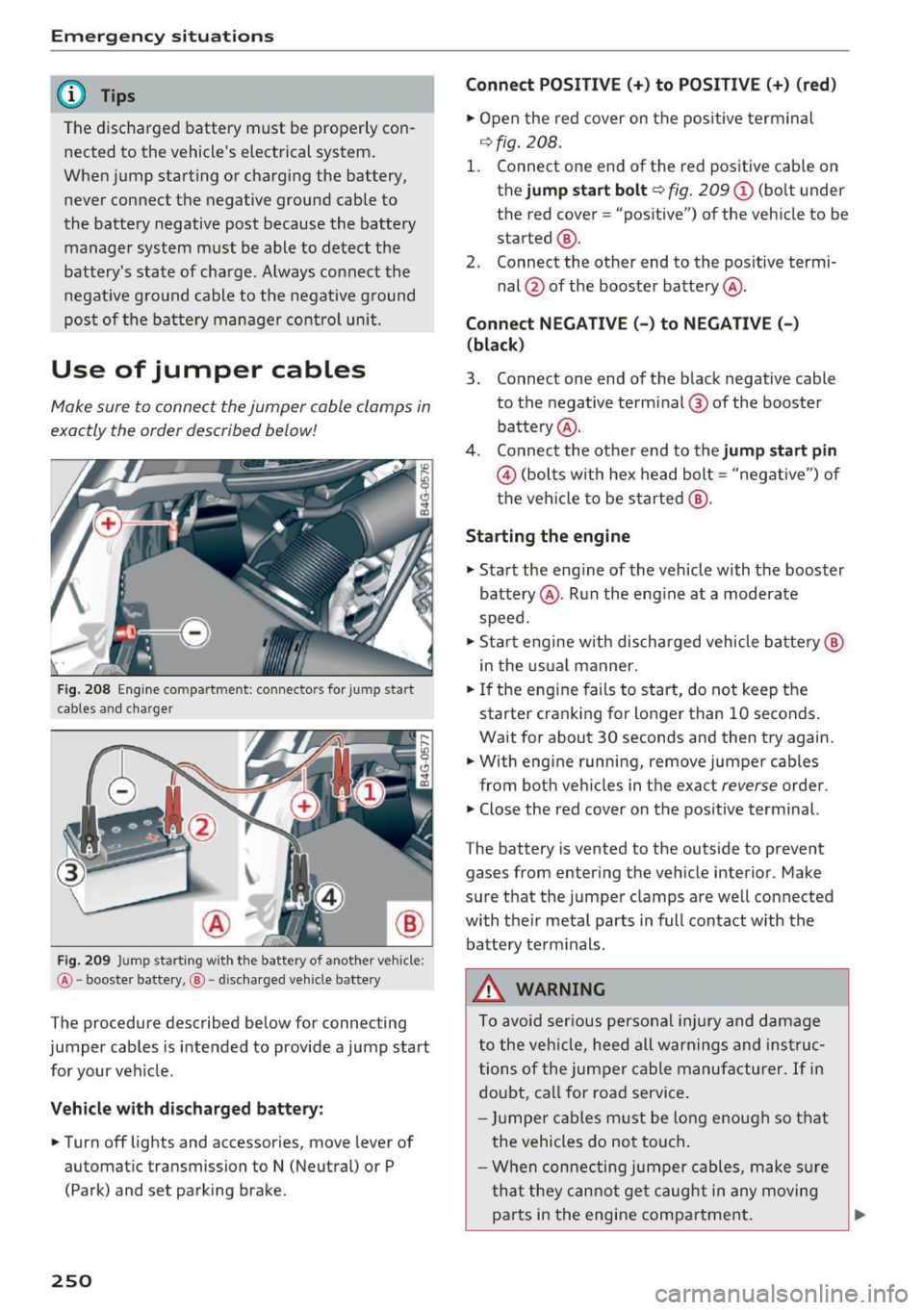
Fig. 208 Engine compartmen t: connecto rs for ju mp start
cables a nd charger
@
Fig. 209 Ju mp starting w ith the battery of another vehicle :
@-booster battery, @- discharged vehicle batte ry
The procedure described below for connecting
jumper cables is intended to provide a jump start
for your veh icle.
Vehicle with discharged battery:
.. Turn
off lights and accessories, move lever of
automatic transmission to
N (Neutral) or P
(Park) and set park ing brake .
250
Connect POSITIVE(+) to POSITIVE (+) (red)
.. Open the red cover on the positive terminal
o::> fig.
208.
1. Connect one end of the red positive cable on
the jump start bolt
Q fig. 209 (i) (bolt under
the red cover= "positive") of the vehicle to be
started @.
2. Connect the other end to the positive termi-
nal@ of the booster battery @.
Connect NEGATIVE(-) to NEGATIVE(-)
(black)
3. Connect one end of the black negative cable to the negative terminal ® of the booster
battery @.
4. Connect the other end to the jump start pin
© (bolts with hex head bolt= "negat ive") of
the vehicle to be started @.
Starting the engine
"' Start the eng ine of the vehicle with the booster
battery @. Run the eng ine at a moderate
speed.
"' Start engine w ith discharged vehicle battery@
in the usual manner.
"' If the engine fails to start, do not keep the
starter cranking for longer than 10 seconds.
Wait for about 30 seconds and then try again.
"' With engine running, remove jumper cables
from both vehicles in the exact
reverse order.
"' Close the red cover on the positive terminal.
The battery is vented to the outside to prevent gases from entering the vehicle interior . Make
sure that the jumper clamps are well connected
with their metal parts in full contact w ith the
batte ry terminals.
A WARNING
To avoid serious personal inju ry and damage
to the veh icle, heed all warnings and instruc
tions of the jumper cable manufacturer.
If in
doubt, call for road service.
- Jumper cables must be long enough so that
the vehicles do not touch .
- When connecting jumper cables, make sur e
that they cannot get caug ht in any moving
pa rts in the engine compartment. ..,.
Page 262 of 280
Consumer information
scope of maintenance and repairs which can be
carried out by vehicle owners.
Also, safety and
environmental
concerns place very strict limits
on the nature of repairs and adjustments to en
gine and transmission parts which an owner can
perform .
Maintenance, adjustments and repairs usually re
quire special tools, testing devices and other
equipment available to specially trained work
shop personnel in order to assure proper per
formance, reliability and safety of the vehicle and
its many systems .
Improper maintenance, adjustments and repairs
can impair the operation and reliability of your
vehicle and even void your vehicle warranty.
Therefore, proof of servicing in accordance with
the maintenance schedule may be a condition for
upholding a possible warranty claim made within
the warranty period.
Above all, operational safety can be adversely af
fected, creating unnecessary risks for you and
your passengers.
If in doubt about any servicing, have it done by
your authorized Audi dealer or any other properly
equ ipped and qualified workshop. We strongly
urge you to give your authorized Audi dealer the
opportunity to perform all scheduled mainte
nance and necessary repairs. Your dealer has the
facilities, original parts and trained specialists to keep your vehicle running properly.
Performing limited maintenance yourself
The following pages describe a limited number of procedures which can be performed on your vehi
cle with ordinary tools, should the need arise and
trained personnel be unavailable. Before per
forming any of these procedures, always thor
oughly read all of the applicable text and careful
ly follow the instructions given. Always rigorously
observe the
WARNINGS provided.
Before you check anything in the engine com
partment, always read and heed all WARNINGS
c> & and c> & in Working in the engine compart
ment on page 198.
260
A WARNING
-
-Serious personal injury may occur as a result
of improperly performed maintenance, ad
justments or repairs .
- Always be extremely careful when working
on the vehicle. Always follow commonly ac
cepted safety practices and general com
mon sense. Never risk personal injury.
- Do not attempt any of the maintenance,
checks or repairs described on the following pages if you are not fully familiar with these
or other procedures with respect to the ve hicle, or are uncertain how to proceed.
- Do not do any work without the proper tools
and equipment. Have the necessary work
done by your authorized Audi dealer or an
other properly equipped and qualified work
shop.
- The engine compartment of any motor vehi
cle is a potentially hazardous area. Never
reach into the area around or touch the radi
ator fan. It is temperature controlled and
can switch on suddenly - even when the en
gine is off. The radiator fan switches on au
tomatically when the coolant reaches a cer
tain temperature and will continue to run
until the coolant temperature drops.
- Always switch off the ignition before anyone
gets under the vehicle.
- Always support your vehicle with safety
stands if it is necessary to work underneath
the vehicle. The jack supplied with the vehi
cle is not adequate for this purpose and
could collapse causing serious personal in
Jury.
- If you must work underneath the vehicle
with the wheels on the ground, always make
sure the vehicle is on level ground, that the
wheels are always securely blocked and that
the engine cannot be started.
- Always make sure the transmission selector
lever (automatic transmission) is in P (Park
position) and the park brake is applied. ..,